An Improved TEM Antenna Designing Used in Electromagnetic
Pulse Directed Radiation
Hang Li1 and Shoulin Yin2, *
Abstract—As we all know, traditional transmission electromagnetic pulse simulator has restricted test space problem. This paper proposes a new directed radiation fast rising time electromagnetic pulse (FREMP) simulator scheme which is based on transverse electric magnetic (TEM) wave antenna of a wire edge curl structure. Through numerical simulation, we study the influence of the parameters of wire edge curl TEM horn antenna and the effect of absorption resistance on radiation field. The simulation results show that the wire edge curl TEM horn antenna can effectively improve the ability of low frequency radiation. It can provide a theoretical support for developing FREMP simulator. We also demonstrate the feasibility of developing FREMP simulator using wire edge curl TEM horn antenna through experiments. Finally, the experimental results show that the radiation field of FREMP simulator developed by wire edge curl TEM horn antenna can meet high-altitude nuclear electromagnetic pulse (HEMP) requirements.
1. INTRODUCTION
In general, electromagnetic pulse (EMP) simulators contain transmission EMP simulator and radiation type EMP simulator [1, 2]. Transmission type electromagnetic pulse simulator usually takes parallel plate, Gigahertz Transverse Electro Magnetic (GTEM) and TEM cell transmission line as electromagnetic pulse forming devices. It will form the same electromagnetic pulse field as pulse waveform in transmission line [3]. Traditional transmission EMP simulator produces the rise time of pulse waveform which is limited by transmission line length, so large transmission EMP simulator cannot generate steep pulse field frontier. It will restrict the test on high-altitude nuclear electromagnetic pulse (HEMP) for large weapons and equipments. Radiant EMP simulator mainly adopts cage or TEM antenna to radiate drive pulse and form pulse field. The produced radiation field waveform is the derivation of excitation waves which has a steeper rising edge. However, cage antenna is non-directional antenna which results in lower utilization of energy. Compared with cage antenna, TEM horn antenna has some advantages such as constant impedance, broadband, good direction, smaller size, and large effective test area [4]. So many researchers have studied radiant EMP simulator by the TEM antenna. Shao et al. [5] proposed a simple ultra-wideBand exponentially-tapered transverse TEM horn antenna based on ground penetrating radar. Xiong et al. [6] studied gigahertz transverse electromagnetic cell to illustrate coupling effect on metal structure of GTEM cell and antenna of equipment under test (EUT). In this paper, we propose an improved TEM horn antenna. The new directed radiation fast rising time electromagnetic pulse simulator scheme is based on TEM wave antenna of a wire edge curl structure. We analyze the feasibility of directed radiation fast rising time electromagnetic pulse simulator with the method of wire grid edge curl TEM horn antenna through numerical simulation and experiments.
Received 2 April 2015, Accepted 16 September 2015, Scheduled 2 October 2015
* Corresponding author: Shoulin Yin ([email protected]).
1 Shenyang Normal University, China. 2 Shenyang Normal University, No. 253, Huanghe Bei Street, Huanggu District, Shenyang
2. FREMP AND NEW TEM HORN ANTENNA STRUCTURE
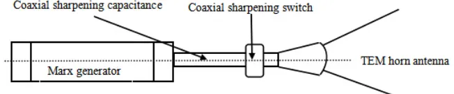
Figure 1 shows the structure of an FREMP simulator. This simulator is composed of marx generator, sharpening device and TEM antenna. Marx generator provides initial pulse. Sharpening device makes the initial pulse more steep. Then TEM antenna forms a satisfactory electromagnetic pulse radiation field. The electromagnetic pulse radiation field, called a transient electromagnetic disturbance radiation field, can occur in the form of a radiated, electric or magnetic field or a conducted electric current depending on the source. Electromagnetic pulse radiation field has the characteristics of short pulse, wide spectrum range, high pulse power, etc.
Figure 1. The structure of FREMP.
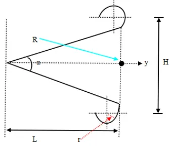
The simplest TEM antenna [7] is constituted by two metal plates with open angle as shown in Fig. 2. In order to improve the low frequency radiation ability of an antenna, we adopt crimping structure at the end of the antenna as shown in Fig. 3, i.e., we add a folded crimping upwards at the end of the antenna. A crimping structure has a small opening and a large opening. A transition piece contains a tapering portion and a non-tapering portion. Between a waveguide and an environment, the transition piece is arranged in the conical horn. A transition between the tapering portion and non-tapering portion is arranged between the small opening and large opening of the conical horn. The crimping antenna keeps a low profile. It has a simple structure. It can not only reduce the radiation patch and floor size of antenna, but also guarantee the bandwidth and gain of antenna and performance before and after radiation pattern. It can also add the current path length. To reduce weight, antenna element adopts a wire grid structure constituted by a hollow aluminum tube, because aluminum material can reduce the loop inductance and it also improves the steepness of the rising edge. Additionally, it can reduce the wind drag. In order to reduce the terminal reflection of the antenna, we add absorption resistance at the end of the antenna. L is the length of antenna, α the angle between the two polar plates, β the aperture angle of antenna pad, r the edge curl TEM antenna’s radius, R the absorption resistance,x,y, zthe direction in space rectangular coordinates, h is the distance between the ends of upper and lower wire grid edges of the TEM horn antenna, and H the distance between the two edge curl centers.
3. THE NEW TEM RADIATING ANTENNA RADIATION FIELD WAVEFORM
Generally speaking, nuclear explosion generates electromagnetic pulse waveform which is similar to double exponential pulse. In order to make up low ability of TEM antenna with low frequency radiation, the drive pulse rise time should be as small as possible, and pulse width should be large enough. Setting excitation source as:
U(t) =U0×k
e−at−e−bt
(1)
whereU0= 0.8 MV,a= 1.2×10⁷s−1,b= 0.9×10⁹s−1,k= 0.98. t is measurement time. Pulse rising
frontier is 1.85 ns. Half peak width of pulse is 49 ns. Upper frequency of pulse is 598 MHz.
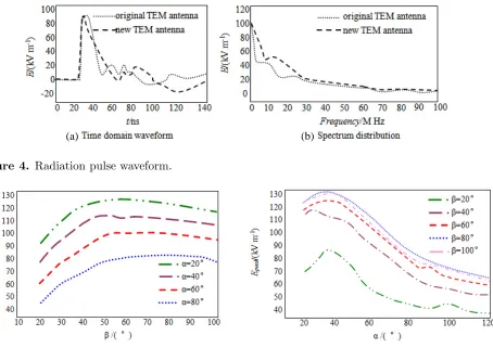
lower triangle plates and apply the double exponential pulse in formula (1) into discrete port. Through simulation experiments, Fig. 4(a) is the time domain waveform and Fig. 4(b) the corresponding spectrum distribution.
From Fig. 4(a), we can see that time domain waveform is close to double exponential wave. The rise time and peak field strength of the two kinds of antenna radiation pulse waveform are similar when t=<40 ns. But the decline part of pulse has a bigger difference whent >40 ns. Comparing with the two TEM antenna radiation field waveform, we can get that the pulse width of edge curl TEM antenna radiation field is greater than the pulse width of the straight TEM antenna radiation. Because the edge part of edge curl antenna increases current moving path and the effective length of the antenna. This process improves low frequency ability of TEM antenna. Radiation pulse waveform spectrum distribution curve in Fig. 4(b) illustrates the advantage. WhenFrequency is less than 30 MHz, the peak field strength of the new TEM antenna is higher than that of TEM antenna. The peak field strength is not affected by frequency with crimping structure. When Frequency is greater than 30 MHz, the peak field strength of the new TEM antenna approaches to TEM antenna. As a whole, the new TEM antenna has good effectiveness. The following section will introduce the structure optimization of improved edge curl TEM antenna.
4. DETAILED EDGE CURL TEM ANTENNA ANALYSIS
When antenna arm length is determined, vertex angle of antenna pad, the angle between the two polar plates and absorption resistance all can have an effect on the radiation characteristic of edge curl TEM antenna. The length of antenna, the distance between the endd of wire grid edges of the curl TEM horn antenna and the angle between the two polar plates are three important parameters in edge curl TEM antenna as shown in Fig. 3. The relations among field strength of edge curl TEM antenna and vertex angle, aperture angle, radius can be expressed as: Epeak=−IHLR4π β2cosακ[
1
rβ
2
+rβ1 3]e−rβrˆ. I is electric current. kis constant.
4.1. Relation between Vertex Angle of Antenna Pad and Peak Field Strength
Figure 5 shows that the maximum electric field intensity distribution is different when α = 20◦, 40◦, 60◦, 80◦. With the increase of antenna aperture angle α, the peak field strength of antenna Epeak is
also increased. When β >60◦,Epeak has little change. Whenβ >80◦,Epeak decreases slowly. Because
the antenna pad vertex angle becomes small or large, TEM antenna generates directional variation. In the practical engineering application, the range of antenna pad vertex angle is 60◦ ∼80◦.
Figure 2. The structure of original TEM horn antenna.
(a) (b)
Figure 4. Radiation pulse waveform.
Figure 5. Relation betweenβ and Epeak. Figure 6. Relation betweenα and Epeak.
4.2. Relation between Aperture Angle of Antenna Pad and Peak Field Strength
Figure 6 shows that the maximum electric field intensity distribution is different when β = 20◦, 40◦, 60◦, 80◦, 100◦. Whenα <40◦, with the increase of antenna aperture angle α, the peak field strength of antenna Epeak is also increased. When α > 40◦, Epeak decreases rapidly. With the increase of α,
antenna outward radiation ability is strengthened. It also suffers from serious interference. So Epeak
decreases rapidly. And the angle of antenna pad should be between 40◦ and 50◦.
4.3. Effect of Edge Curl TEM Antenna’s Radius on Radiation Field
Figure 7 shows that the maximum electric field intensity distribution is different when edge curl TEM antenna’s radius r = 0.5, 1, 2 m. Although r is different, pulse peak and rising edge of Epeak change
little. The falling edge changes a lot. With the increase of r, pulse half wave width of Epeak becomes
very large. From the Fig. 7, when r = 2 m, the half wave width of radiation pulse waveform is about 20 ns which satisfies the latest standard of MIL-STD-461F. We can use radiation pulse field to conduct experiments.
4.4. Effect of Absorption Resistance on Radiation Field
In order to improve low frequency radiation ability and reduce terminal reflection of antenna, we add an absorption resistance at the end of the antenna. So the antenna becomes traveling wave antenna.
Figure 7. Relation betweenr andEpeak. Figure 8. Relation betweenR and Epeak.
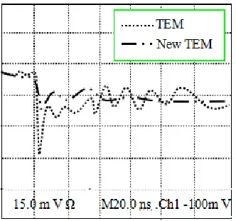
Figure 9. Error of pulse electric filed waveform.
by antenna terminal reflection, because the current passes antenna terminal and generates magnetic field. Based on optical principle, it uses edge horn as reflector and reflects magnetic field. If we select appropriate absorption resistance, resistance can absorb most of the reflection current.
In the radiant nuclear electromagnetic pulse simulator designing process, absorption resistance has an effect on the wave shaping resistance. Supposing that equivalent capacitance of Marx generator is Cn, absorption resistance is R. So drive pulse width dhw = 0.7RCn. The value of reflection coefficient is a complex number. It has size and phase. If the mould of reflection coefficient is invariant and phase of every point different, antenna terminal reflection can lead to quantify the level of a mismatch.
Through the above analysis, we get the optimal experimental data which provide a powerful support for this paper’s new scheme.
5. NUMERICAL EXAMPLE AND ANALYSIS
Figure 9 shows the error of pulse electric field waveform of traditional TEM antenna. The error of pulse electric field waveform is bigger than new TEM antenna. It has a longer convergence time. The edge curl TEM horn antenna’s error is small. Stability convergence time of pulse electric field waveform is faster. The experiments show that falling edge time at different positions of pulse electric field waveform is about 2 ns and pulse width about 19 ns. That meets the HEMP standard requirement of IEC 61000-4-25, MIL-STD-464C and GJB 1389A.
6. CONCLUSION
In this paper, we use wire edge curl TEM horn antenna to design nuclear electromagnetic pulse simulator. The experiments results show that:
(1) Wire edge curl TEM horn antenna can improve the low frequency radiation ability effectively. (2) Vertex angle of antenna pad, radius of edge curl and aperture angle of wire edge curl TEM horn have a significant effect on peak field strength and half wave width. So through experiments we know 40◦ < α <50◦, 60◦ < β <80◦. r should be large enough.
(3) The new directed radiation fast rising time electromagnetic pulse (FREMP) simulator based on transverse electric magnetic (TEM) wave antenna of a wire edge curl structure meets the requirement of HEMP.
REFERENCES
1. Efremov, A. M., V. I. Koshelev, B. M. Kovalchuk, et al., “Generation and radiation of ultra-wideband electromagnetic pulses with high stability and effective potential,” Laser and Particle Beams, Vol. 32, No. 3, 413–418, 2014.
2. Zhou, X. and T.-J. Cui, “Efficient evaluation of near-field time-domain physical-optics integral using locally expanded Green function approximation,” Progress In Electromagnetics Research, Vol. 150, 41–48, 2015.
3. Cummer S. A., M. S. Briggs, J. R. Dwyer, et al., “The source altitude, electric current, and intrinsic brightness of terrestrial gamma ray flashes,” Geophysical Research Letters, Vol. 41, No. 23, 8586– 8593, Dec. 16, 2014.
4. Umbarkar, S. B., H. A. Mangalvedekar, S. Bindu, et al., “Analysis of HTEM horn-type antenna for high-power impulse radiation applications,” Vol. 42, No. 10, 3288–3294, 2014.
5. Shao, J., G. Liu, Y. Ji, et al., “UWB TEM horn antenna for the asphalt pavement investigation,”
Journal of Electronics (China), Vol. 31, No. 1, 24–28, 2014.
6. Xiong, X., W. Hong, S. Xie, et al., “Impedance model of dipole antenna combined with the structure parameters of GTEM cell,” Proceedings of the 2014 Sixth International Conference on Computational Intelligence, Communication Systems and Networks, IEEE Computer Society, 44– 47, 2014.