Implementation of Droop Control in DFIG Based
Wind Turbines
Nallagatla Vasundhara
1, Kurakula Vimala Kumar
2, Thalluru Anil Kumar
3 1M.Tech Student,
2Assistant Professor,
3Professor
1,2Dept. of EEE, JNTUA College of Engineering, Pulivendhula, Andhrapradesh, India 3Dept. of EEE, CVSR College of Engineering, Hyderabad, Telangana, India
Abstract
Wind energy is the renewable energy which will plays a major role of electrical energy generation in near future, but due to irregular nature of wind, there will be problems in power system reliability and stability. Normally used doubly-fed induction generators (DFIGs) do not take part in frequency regulation whether short or long term. But it is very important to use wind generators for autonomous frequency regulation. In this paper we will achieve this with droop control i.e., torque droop and power droop methods are introduced in DFIG based units and also studied about how both techniques participated in frequency stability. Sensitivity reviews, with respect to the presence of turbine and inverter-based machines in micro-grids and wind speed changes and independent mode operation with only wind-generators are conducted. to get better results fuzzy logic controller is used. Time-domain simulation is used to check the analytical results.
Key words: droop, small-signal modeling, power sharing, stability, wind, DFIG, Fuzzy Logic Controller and stand alone operation.
1.
Introduction
The power grid interaction and effects of wind turbines was the focus of research from years. Here mainly concerned on the irregular nature of the power generated from wind turbines. These concerns also make a back step to further increase the integration of wind power. Wind turbines can operate either at constant speed or varying speed. In case of constant speed wind turbine the generator is directly connected to the grid but in case of variable-speed wind turbine the generator is connected to the electrical grid via controlled power electronic equipment. There are so many reasons behind usage of variable-speed wind turbines; among that main reason is possibility of reduction in stress of mechanical structure, noise mitigation and controlling possibility of reactive and active power. The ratings of recently utilized wind turbine generators are in the range of 3-5 MW, which are based on the operation of varying-speed with controlling of pitch using a direct driven synchronous (DDS) generator (without gear box) or a doubly-fed induction generator
(DFIG). Induction generators with invariable-speed and controlling halt are considered as infeasible for these sorts of wind turbines. The most popularly used DFIG’s vital beauty is that the equipment of power electronic has to deal only 20-30% of the total system power, which means that the losses in the power electronic equipment of DDS generators are high when compare to DFIG, in addition to the cost saving with a smaller converter. In this paper, it is shown that the employment of usual power-droop in non-dispatchable wind power generation gives problems which could not discussed in normal dispatchable distributed generation (DG) units. This paper also gives simple but efficient method of torque droop will solve these difficulties. On the contrary, such a method could not be applied to usual inverter-based dispatchable DG units.
2.
Existing System
comparative results from other techniques tell its slower behavior. Pitch-angel control is suggested for high wind speed, while torque can be used for under-rated speeds [4], [14]. In spite of its advantages, this method wants wind speed measurement for switching between both control methods. By means of both methods at the same time based on a fuzzy control is preferred in [9]; on the other hand, similar to every discussed references, complete stability analysis is not provided. Further, none of mentioned papers, except a recently published article [17], indicate the stand-alone operation of DFIG-wind generators in the lack of any dispatchable sources. On the other hand, the work in [17] does not also provide any stability analysis. In addition, it considers only constant wind speed with always extreme generation rather than modifying the widely-accepted usual control method, it proposes a totally fresh and somewhat complex method.
3.
Proposed System
This paper represents a droop control method to include wind generation in autonomous frequency/power regulation in remote micro grids, and in weak power grids with reduced inertia. Droop control is implemented on both torque and power by simple changes in the usual DFIG-based wind power controller. Small-signal modeling and Eigen-values analyses are engaged to discriminate the differences between both methods and judge their effects on frequency stability. Most of the sensitivity studies are conducted with respect to the turbine and inverter-based generators presence in micro grids; and pitch-angle controller impacts, changing in speed of wind and isolated mode operation with only wind generators. At last, to confirm the analytical analysis, results with time-domain simulation are presented with the comparison of PI and FLC. In recent years, Fuzzy logic control systems are providing enough hope in industrial systems, consumer products, commercial systems, and even in decision support systems. The word ‘fuzzy’ refers to the dealing capability with general or undefined inputs. To specify the relationship between the input and the output, rather utilization of complicated mathematical analysis, linguistic descriptions will be used in fuzzy logic systems. The contributions of this paper to the research field are:
Developing a small-signal model for wind droop methods in DFIG-based wind generators. The models are used for comparative analysis and sensitivity studies;
Enquiring the effect of wind-droop on micro grid frequency stability by Eigen-values studies, and comparing the effect of wind-droop to real inertia;
Provided that a systematic approach to coordinate wind-droop with other energy sources available in a usual micro grid system (e.g., inverter- and turbine-based generators);
Investigating the stand-alone operation of wind generation (without any dispatchable sources) in a micro grid with real wind speed pattern.
4.
Droop Implementation in DFIG
Fig. 1 represents a DFIG-based wind power generator with interactive control for stiff-grid connected and weak micro-grid procedure modes. In the DFIG system no need of voltage regulation when the generator is connected to a stiff grid. In the mode, the DFIG is maintained to work at unity power factor. On the converse, in remote or weak grid mode the DFIG is forced to control its terminal voltage via the rotor-side converter (RSC) while the grid-side converter is restricted to operate at unity power factor to reduce the converter rating. The terminal voltage controller generates the reference reactive current component. Additional information on DFIG control structures can be found in [12] and [19]. The torque control will be discussed in this paper with detail. For the period of connection to a stiff grid, a DFIG is restricted to take out the maximum obtainable power/torque, and it cannot participate in frequency/active power regulation. On the converse, in the remote/weak grid mode, it moves to droop control, which can be realized by torque-droop or power-droop. The reference torque is utilized to produce the reference active current component. Usual proportional-integral (PI) controllers are utilized to control the RSC currents. To include wind in micro-grid frequency regulation and implementing droop, sufficient preserve power should be measured in wind power generation. The optimum torque, for constant pitch-angle is
(1)
where ω r is DFIG rotational speed. By multiplying the right side term of equation (1) with a deloading factor , the operating point will move away from the maximum extraction point. The effect of on the wind generation output and rotational speed is shown in fig1. While this deviation is considered as a loss, it allows the droop implementation:
(2)
A. TORQUE-DROOP
The power/frequency droop is given by
(3)
(4)
To examine the effect of this adjustment should model the wind power generation with the wind turbine and also need DFIG and the back-to-back converter.
(5)
(6)
Where HDFIG is inertia constant, is electrical active power output, is mechanical input to turbine, is air density, Cp is the power coefficient of the wind turbine, is tip ratio, is effective area covered by turbine blades,
is pitch angle and is wind speed.
For small signal analysis (5) and (6) are modified as (7) and (8) respectively
(7)
(8)
Where
(9)
(10)
(11) The output power with torque droop is given by
(12)
Fig.1. DFIG-based wind power generator with interactive control for stiff-grid connected and weak/micro-grid operation modes
B. POWER DROOP
The term in the denominator is replaced by reference torque is given as
(13)
The output power with power droop is given by
Here the steady state and dynamic behavior will be changed.
C. STEADY-STATE ANALYSIS
The steady-state response of wind power generation to change in frequency regulation with torque droop is given by
(15)
The steady-state response wind power generation to change in frequency regulation with power droop is given by
(16)
The effective droop factor depends on initial wind speed, initial micro-grid frequency and Kf. So the effective droop factors for torque and power droop are given by (17) and (18) respectively
The value of kf should be lower than one, higher than one is undesirable. The maximum possible droop factor is given by (19).
(19)
(20)
D. STABILITY ANALYSIS
For more studies, figure 1 shows a real system named as medium-voltage rural distribution system. The section after the circuit breaker B2 has the potentiality to work in ground mode and establishes the micro-grid. The general load of this section is 3.77 MW/1.24 mvar.
Fig. 2. System under-study
It consist two DG units where the first is a variable-speed wind turbine connected to a 2.5 MVA DFIG with its rotor ported by back-to-back converters and DG2 is a 2.5MVA synchronous generator with droop and innervation control systems.
5.
Simulation Results
Time-domain simulation, using MATLAB, is used to verify the experimental results under study. Here two cases are studied,
Case2: uses only wind power generation and again each case has different methods. The droop and innervation system models are also integrated.
A. GAS TURBINE PLUS WIND
Initially, unchanged wind speed is regarded to lessen the complexity. Then after, to disclose a more realistic case, a real wind speed pattern is used.
1) constant wind speed:
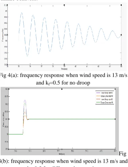
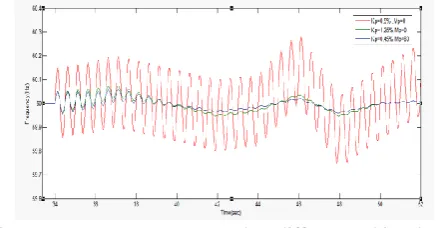
a)Under-Rated Speed: An intended islanding occurs at t=35s.The system frequency without wind-droop and with power- or torque-droop at various droop gains was observed in fig3. Here both the final frequency and the transient behaviors are improved even with the low X/R ratio. It also confirms larger mp results in improved dynamic behavior.
Fig 4(a): frequency response when wind speed is 13 m/s and kf=0.5 for no droop
Fig 4(b): frequency response when wind speed is 13 m/s and
kf=0.5 for different droop gains
b)Under-Speeding: It was earlier shown that choosing higher kf i.e. Greater than one may effect in negative effective droop. The wind generator output when kf=1.5 was examined. While the system has extreme generation similar to the pervious case, and frequency has greater than before after islanding, the wind power output, in spite of the idea of implementing droop, has also improved. In fact, wind-droop with under-speeding dictates higher fluctuations to dispatchable sources outputs and it is not able to feed a micro-grid alone.
Fig 5: frequency and wind power generation responses when wind speed is constant at 13 m/s and kf=1.5,mp=40
c ) Inverter Interaction: In the system, to the bus 8 an inverter-based DG unit is added and turbine droop factor has also been altered. The system frequency in different cases, both the steady state and the dynamic behaviors get worse by decreasing the inverter droop factor, the system stability was improved due to the presence of wind-droop shown in fig4. It able to stabilize the unstable system as predicated by the analytical results.
Figure 6: Real wind speed pattern
2)variable wind speed: Here a real wind speed pattern, which is resulting from real measured wind speed data, is used shown in fig.6.
Figure 7: Frequency responses when wind speed is varying. Islanding had taken place long enough before
wind speed starts to change
Figure 8: Gas turbine generator output power response when wind speed is varying. Islanding had taken place
long enough before wind speed starts to change
b)Turbine Droop Factor: On lowering kp the may result in instability, in spite of its positive effect on steady-state frequency deviation. It also verifies that the existence of wind-droop allows turbine to experience lower kp without facing stability problems shown in fig9.
Figure 9: Frequency response when different turbine droop factors, Kp, are adopted
B. STAND-ALONE WIND
With proper energy management, sensitive loads can be fed from a wind generation under the outage of dispatchable resources or other micro-grid contingencies. In this case, it is understood that wind generation is adequate for important loads in a micro-grid and simply studies short-term frequency stability issues (not long-term power dispatching). It should be noted that with the greatly increasing penetration levels of wind power in power systems and advances in forecasting and energy management methods, this case is very likely to happen in near-term micro-grids.
Figure 10: Frequency response for standalone wind power generation
1) Single Wind Generation Unit:Here, the gas turbine generator unit is detached and load 2 is altered for
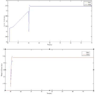
generation-load matching. Green and red-dashed lines show system loading levels concerning wind speed; in fact, they indicate the minimum wind speed required to supply the loads. It should be noted that in steady-state in both cases, available wind power is sufficient. However, in some cases, e.g., for the green line, some short-term deficiencies occur. The frequency in both cases, which are stable shown in fig9. This experiment reveals that short-term deficiency in available wind power could be afforded due the kinetic energy provided by the rotating mass. The active and reactive power output of wind generator in both cases illustrated shown in fig11.
(a)
(b)
Figure 11: Wind (a) active power response and (b) reactive power response
2) Multiple Wind-Power Generators: Here, load 2 is restored and another wind power generator is added to bus 7, the same place of the gas turbine unit. Like pervious part first, constant wind speed is utilized; then a typical wind speed profile is employed.
(b)
Figure 12: changes in active power output of stand-alone wind power generations with different wind speeds, Vw,
when droop is implemented in (a) torque and (b) power
(a)
(b)
Figure 13: changes in reactive power output of stand-alone wind power generations with different wind speeds, Vw,
when droop is implemented in (a) torque and (b) power
a) Constant Wind Speed:
One of the generators works at 14m/s where the other operates at Vw=9.5m/s and the droop factor is the equal for both. The output power responses of both generators when torque-droop and power -droop is used (fig.12). With torque-droop, generator with higher wind speed has higher share in power regulation and a higher effective droop factor. With power-droop there is nearly equal power sharing and almost constant effective droop factor while the deloaded power is not constant, could result in instability. The lower wind speed is decreased from 9.5 to 9 m/s. Yet again in power-droop method, the DG unit with lower wind speed and less available power is forced to provide nearly the same power as the other unit with higher wind speed so the inability of this DG unit leads to instability as a result micro-grid failure (fig 14). It is praiseworthy to talk about that exactly the same case but with torque-droop remains stable.
Figure 14: frequency vs time when two stand-alone wind generators with identical wind speeds regulating the micro-grid frequency
b) Variable Wind Speed: Similar Wind Speed Patterns:
Both wind power generators experience the similar wind speed pattern. The frequency regulation and power sharing responses was shown. Both DG units share the equal amount of the active power as they have same parameters shown in figs14 and 15.
Figure 14: wind (a) active power and (b) reactive power generation when two stand-alone wind generators with identical wind speeds regulate micro-grid frequency
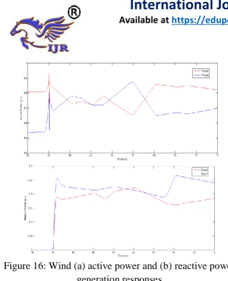
2) Different Wind Speed Patterns: One DG unit with different wind speed pattern is used while the other unit has the previous wind speed pattern .The power sharing performance was shown. Because of variable wind speed and dependency of the effective droop factor, a unit with higher wind speed generates more power which seems reasonably helpful.
Figure 16: Wind (a) active power and (b) reactive power generation responses
Compatibility Between Torque- and Power-Droops: On comparing both droop methods even with the same parameters power sharing is not completely equal due to the impact of the effective droop factor(Fig.19 and 20).
Figure 17: Micro-grid frequency response with different variable wind speed patterns
Figure 18: wind (a) active power and (b) reactive power generation responses
Figure 19: Micro-grid frequency response
Frequency response for stand-alone wind power generation, active and reactive power response for partially deficient generation was compared with PI and FLC and better responses observed with FLC shown in Fig 20. Compatibility between Torque and Power Droop by using Fuzzy Logic Controller: By using FLC, the frequency response of micro-grid was improved and it was shown in Fig 21.
Figure 20: wind (a) active power (b) reactive power and (c) frequency response for stand-alone wind power
generation
0 0.1 0.2 0.3 0.4 0.5 0.6 0.7 0.8 0.9 1 0
0.1 0.2 0.3 0.4 0.5 0.6 0.7 0.8
Active power vs time
time [s]
a
c
t
iv
e
p
o
w
e
r
(
p
.
u
)
With PI With FLC
0 0.1 0.2 0.3 0.4 0.5 0.6 0.7 0.8 0.9 1
0 0.05 0.1 0.15 0.2
Reactive power vs time
time [s]
r
e
a
c
t
iv
e
p
o
w
e
r
(
p
.
u
)
With PI With FLC
0 0.1 0.2 0.3 0.4 0.5 0.6 0.7 0.8 0.9 1 59
59.2 59.4 59.6 59.8 60 60.2 60.4 60.6
Change in Freqency in Hz
time [s]
Fr
e
q
u
e
n
c
y
(
H
z
)
Figure 21: wind (a) active power response, (b) reactive power response and (c) frequency response when PI and
FLC used
6.
Conclusion
The effects of the torque- and power-droop implementation in DFIG units were analyzed. The variation of effective torque-droop could give in greater stability when compared to the power-droop method, it was shown by small-signal analysis. The positive effect of wind-droop on system frequency-stability, turbine governor and inverter droop functions showed. The wind power generation with autonomous frequency regulation has the capability to stabilize the frequency in an isolated micro-grid was showed. Time-domain simulations verified for all results. Load sharing with different wind-droop methods and using Fuzzy Logic Controller were examined. And also for stand-alone wind power generation frequency response was improved by using FLC.
References
[1] t. Bhattacharya and l. Umanand, ―negative sequence compensation within fundamental positive sequence reference frame for a stiff micro-grid generation in a wind power system using slip ring induction machine,‖ iet elect. Power applicat., vol. 3, no. 6, pp. 520–530, 2009.
[2] global wind energy outlook, 2010 [online]. Available: http://www.gwec.net[3] 20% wind energy by 2030: increasing wind energy's contribution to u.s. electricity supply. Washington, dc, usa, jul. 2008, u. S. Department of energy.
[3] g. Ramtharan, j. B. Ekanayake, and n. Jenkins, ―frequency support from doubly fed induction generator wind turbines,‖ iet renew. Power gen., vol. 1, pp. 3–9, 2007.
[4] j. Morren, j. Pierik, and s. W. H. De haan, ―inertial response of variable speed wind turbines,‖ elect. Power syst. Res., vol. 76, no. 11, pp.980–987, jul. 2006.
[5] l. Wu and d. G. Infield, ―towards an assessment of power system frequency support from wind plant— modeling aggregate inertial response,‖ ieee trans. Power syst., to be published.
[6] m. F. M. Araniet al., ―implementing virtual inertia in
DFIG-based wind power generation,‖ ieee trans. Power syst., vol. 28, no. 2, pp.1373–1384, may 2013.
[7] a. Teninge, c. Jecu, d. Roye, s. Bacha, j. Duval, and r. Belhomme,―contribution to frequency control through wind turbine inertial energy storage,‖ iet renew. Power gen., vol. 3, no. 3, pp. 358–370, sep.2009.
[8] v. Courtecuisse, m. El-mokadem, c. Saudemont, b. Robyns, and j. Deuse, ―experiment of a wind generator participation to frequency control,‖ in proc. Wind power to the grid—epe wind energy chapter1st seminar, mar. 27– 28, 2008.
[9] b. H. Chowdhury and h. T. Ma, ―frequency regulation with wind power plants,‖ in proc. Ieee power and energy society general meeting—conversion and delivery of electrical energy in the 21stcentury, jul. 20–24, 2008.[11] r. G. De almeida, e. D. Castronuovo, and j. A. Peas lopes, ―optimum generation control in wind parks when carrying out system operator requests,‖ ieee trans. Power syst., vol. 21, no. 2, pp. 718–725, may 2006.
[10] m. Shahabi, m. R. Haghifam, m. Mohamadian, and s. A. Nabavi-niaki, ―microgrid dynamic performance improvement using a doublyfed induction wind generator,‖
ieee trans energy converse., vol. 24,no. 1, pp. 137–145, mar. 2009.
[11] k. Clark et al., modeling of ge wind turbine-generators for grid studies, general electric international, tech. Rep., 2010.
0 0.1 0.2 0.3 0.4 0.5 0.6 0.7 0.8 0.9 1 0 0.1 0.2 0.3 0.4 0.5 0.6 0.7 0.8 0.9
Active power vs time
time [s] P [p u] With PI With FLC
0 0.1 0.2 0.3 0.4 0.5 0.6 0.7 0.8 0.9 1
0 0.05 0.1 0.15 0.2 0.25
Reactive power vs time
time [s] Q [p u ] With PI With FLC
0 0.1 0.2 0.3 0.4 0.5 0.6 0.7 0.8 0.9 1 0 10 20 30 40 50 60 70
Change in Freqency in Hz
[12] e. Loukarakiset al., ―frequency control support and
participation methods provided by wind generation,‖ in