Simulation and Analysis of Improved Incremental Conductance
Algorithm with Ann Based Solar Pv System
1B. SAI NIKITHA, 2N. RAM CHANDER
1 PG Scholar, B V Raju Institute of Technology (Autonomous), Narsapur, Hyderabad, Telangana, India. 2Associate Professor, B V Raju Institute of Technology (Autonomous), Narsapur, Hyderabad, Telangana, India.
ABSTRACT: An adaptive and optimal control strategy for a solar photovoltaic (PV) system is proposed in this paper. The control strategy ensures that the solar PV panel is always perpendicular to sunlight and simultaneously operated at its maximum power point (MPP) for continuously harvesting maximum power. The proposed control strategy is the control combination between the solar tracker (ST) and MPP tracker (MPPT) that can greatly improve the generated electricity from solar PV systems. Regarding the ST system, the paper presents two drive approaches including open- and closed-loop drives. Additionally, the paper also proposes an improved incremental conductance (InC) algorithm for enhancing the speed of the MPP tracking of a solar PV panel under various atmospheric conditions as well as guaranteeing that the operating point always moves towards the MPP using this proposed algorithm. Here we are using ANN controller compared to other controllers i.e. ANN is non-paramateric model while most of statistical methods are parametric model that need higher background of statistic. In addition, using the ANN controller for a nonlinear system allows for a reduction of uncertain effects in the system control and improve the efficiency the simulation results shows the effectiveness of the proposal under various atmospheric conditions.
Index Terms—Maximum power point tracker (MPPT),
solar tracker (ST), solar PV panel, ANN.
1. INTRODUCTION
The renewable energy especially photovoltaic technology (PV) will be increasing day to day [3]. This type of energy is freely available in nature and also it cleans the environment. Moreover, we often speak of a "green energy", as totally avoids the pollution produced by traditional sources.
Compared to conventional fossil fuel energy sources, renewable energy sources have the following major advantages: they are sustainable, never going to run out, freely available and non-polluting. Photovoltaic (PV) is a method of generating electrical power by converting solar radiation into direct current electricity using semiconductors that exhibit the photovoltaic effect. Obviously, it is particularly difficult to make considerable improvements in the materials used in the solar PV panels.
Therefore, for improving the performance of the solar PV panels the irradiation intensity received from the sun is increasing, it is an attainable solution. The maximum power point (MPP) [4] is the point on
the I-V curve at which the PV module operates with maximum output power, the MPP varies with changing conditions such as irradiance levels and temperature. To make best use of PV sources, it is essential to always operate at the MPP. The main job for the MPPT is to control the PV system and run it near its Maximum Power Point.
Generally, there is a unique point on the V-I or V-P curve which is called the Maximum Power Point (MPP). This means that the solar PV panel will operate with a maximum efficiency and produce a maximum output power. This paper proposes an improved InC algorithm for tracking a MPP on the V-I characteristic of the solar PV panel. The major approach for maximizing power extraction in solar PV systems is a sun tracking system. The ST system presents two drive approaches including open- and closed-loop drives.
Development and Comparison of an Improved Incremental Conductance Algorithm for Tracking the MPP of a Solar PV Panel using ANN controller is analyzed using simulation results. Finally, the advantages of the proposal are summarized through a comparison with other solar PV panels.
The basic concept in ANN Artificial neural networks (ANNs) or connectionist systems are computing systems inspired by the biological neural networks that constitute animal brains. Such systems learn (progressively improve performance on) tasks by considering examples, generally without task-specific programming.
An ANN is based on a collection of connected units or nodes called artificial neurons (analogous to biological neurons in an animal brain). Each connection (synapse) between neurons can transmit a signal from one to another. The receiving (postsynaptic) neuron can process the signal(s) and then signal neurons connected to it.
2. SOLAR PHOTOVOLTAIC PANEL
A solar PV panel is used for generating electricity. A simple equivalent circuit model for a solar PV cell consists of a real diode in parallel with an ideal current source. The mathematical model of the solar PV cell is given by:
(
)
(1)
( )
(2)
(
)
(3)
where I: the current of the solar PV cell (A);
V: the voltage of the solar PV cell (V); P: the power of the solar PV cell (W) ; Isc: the short-circuit current of the solar PV cell (A);
Voc: the open-circuit voltage of the solar PV cell (V);
I0: the reverse saturation current (A); q: the electron charge (C), q = 1.602 * 10-19 (C);
k: Boltzmann’s constant, k = 1.381 * 10-23 (J/K);
T: the panel temperature (K).
It is realized that the solar PV panels are very sensitive to shading. Therefore, a more accurate equivalent circuit for the solar PV cell is presented to consider the impact of shading as well as account for losses due to the cell’s internal series resistance, contacts and interconnections between cells and modules. Then, the V-I characteristic of the solar PV cell is given by:
(
) ( ) (4)
where Rs and Rp: the resistances used to consider the impact of shading and losses.
Although, the manufacturers try to minimize the effect of both resistances to improve their products, the ideal scenario is not possible. The maximum power is generated by the solar PV cell at a point of the V-I characteristic where the product (V×I) is maximum. This point is known as the MPP and is unique, Fig. 1.
Fig.1. Important points in the V-I and V-P characteristics of a solar PV panel
3. CONTROL STRATEGIES FOR A SOLAR PHOTOVOLTAIC PANEL
Sun Tracking Control:
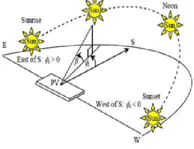
The sun rises from the east and moves across the sky to the west every day. In order to increase solar yield and electricity production from solar PV panels, the idea is to be able to tilt the solar PV panels in the direction which the sun moves throughout the year as well as under varying weather conditions. It can be realized that the more the solar PV panels can face directly towards the sun, the more power can be generated. This idea is called a solar tracker (ST) which orients the solar PV panels towards the sun so that they harness more sunlight.
Fig. 2. Description of the sun's position In the open-loop tracking control strategy, the tracker does not actively find the sun's position but instead determines the position of the sun for a particular site. The tracker receives the current time, day, month and year and then calculates the position of the sun without using feedback. The tracker controls a stepper motor to track the sun's position. It can be realized that no sensor is used in this control strategy. Thus, it is normally called an open-loop ST. The sun's position can be described in terms of its altitude angle, β and its azimuth angle, θ s at any time of day which depend on the latitude, the day number and the time of day, Fig. 2 . The altitude angle, β is given by:
(5)
(6)
Additionally, it depends on the hour angle, H, the azimuth angle, can be estimated as follows:
| | | |
(7) The declination angle, θ is given by:
| |
(8)
where L: the latitude of the site (degrees); δ: the declination angle (degrees);
n: the number of days since January 1; H: the hour angle (degrees).
The solar declination angle, δ is the angle between the plane of the equator and a line drawn from the center of the sun to the center of the earth. It is zero at solar noon and increases by 150 every hour since the earth rotates 3600 in 24 hour. Then, the hour angle is described as follows:
(9)
where ts: the solar time in hours. It is a 24-hour clock with 12:00 as the exact time when the sun is at the highest point in the sky. The open-loop ST must turn the solar PV panel to the east at the sunrise time and stop its motion at the sunset time. It is realized that the altitude angle, β is equal to zero at the sunrise and sunset moments which is described as follows :
(10)
= - (11)
(12)
The hour angle, H, is the inverse cosine function which has positive and negative values. The positive values are used for the sunrise whereas the negative values are used for the sunset. Then, the sunrise and sunset times are obtained by converting the hour angle as follows:
(13)
(14)
On the other hand, the closed-loop ST is based on feedback control principles. In the closed-loop tracking control strategy, the search of the sun's position is implemented at any time of day; light sensors are used and positioned on the solar PV panel. In order to determine the sun's position, two similar light sensors are mounted on the solar PV panel. They are located at the east and west, or south and north, to sense the light source intensity. Then, it makes a comparison between RA and RB as follows. * If RA=RB, then the solar PV panel will be kept its position.
* If RA≠RB and RA<RB, then the solar PV panel will be rotated towards A.
* If RA≠RB and RA>RB, then the solar PV panel will be rotated towards B.
The sample time is the Δt for the comparison and determination of the rotated direction. It is obvious that the solar tracking systems are a good choice for the solar PV systems. The comparisons between the open- and closed-loop STs are shown in Table I. It is easily realized that the openloop ST is simpler, less expensive, more reliable, as well as in need of less maintenance than the closed-loop ST. Nevertheless, its performance can be sometimes lower than that of the closed-loop ST, because the open-loop ST does not observe the output of the processes that it is controlling.
Fig.4. Area partition of the P-V characteristic
MPP Tracking Control:
The InC algorithm is reviewed in Part 1 of this section followed by a description of the improved InC algorithm.
1)InC Algorithm :
The principle of the InC algorithm is that the derivative of the power with respect to the voltage or current becomes zero at the MPP, the power increases with the voltage in the left side of the MPP and the power decreases with the voltage in the right side of the MPP.
This description can be rewritten in the following simple equations:
(15)
(16)
(17)
Where
(18)
(19)
Therefore, the voltage of the PV panels can be adjusted relative to the MPP voltage by measuring the incremental conductance, di/dv and the instantaneous conductance, I/V. It can be realized that the InC algorithm overcomes the oscillation around the MPP when it is reached. When di/dv=- I/V is satisfied, this means that the MPP is reached and the operating point is remained. Otherwise, the operating point must be changed, which can be
determined using the relationship between di/dv and -I/V. Furthermore, the equation (19) shows that:
If , then :the operating point
is to the right of the MPP.
If , then : the operating
point is to the left of the MPP
Additionally, the InC algorithm can track the MPP in the case of rapidly changing atmospheric conditions easily, because this algorithm uses the differential of the operating point, dp/dv. Basically, the algorithm can move the operating point towards the MPP under varying atmospheric conditions. 2) Improved InC Algorithm
An improved InC algorithm is proposed in order to overcome the disadvantages of the InC algorithm. Firstly, the computation for the differential of the operating point, dp/dv is simplified by the following approximation:
(20)
Secondly, the InC algorithm is combined with the Constant Voltage (CV) algorithm [28]-[29] for the estimation of the MPP voltage which can limit the search space for the InC algorithm. Basically, the CV algorithm applies the operating voltage at the MPP which is linearly proportional to the open circuit voltage of PV panels with varying atmospheric conditions. The ratio of VMPP/Voc is commonly used around 76%. Thus, the improved InC algorithm is implemented to divide the P-V characteristic into three areas referred to as area 1, area 2 and area 3, where area 1 is from 0 to 70%Voc, area 2 is from 70%Voc to 80%Voc and area 3 is from 80%Voc to Voc. Area 2 is the area including the MPP, Fig. 4. It can be realized that the improved InC algorithm only needs to search the MPP within area 2, from 70%Voc to 80%Voc. This means that:
(21)
Fig.5. Flow chart of the improved InC algorithm
4. ARTIFICIAL NEURAL NETWORK Introduction
In the last few decades, as the chemists have get accustomed to the use of computers and consequently to the implementation of different complex statistical methods. With the increasing accuracy and precision of analytical measuring methods it become clear that all effects that are of interest cannot be described by simple uni-variate and even not by the linear multivariate correlations precise, a set of methods, that have recently found very intensive use among chemists are the artificial neural networks (or ANNs for short).
Therefore, the analytical chemists are always eager to try all new methods that are available to solve such problems. One of the methods, or to say more Due to the fact that this is not one, but several different methods featuring a wide variety of different architectures learning strategies and applications.
Fig 6.Neural network as a black-box featuring the non-linear relationship between the multivariate input
variables and multi-variate responses
BASIC CONCEPTS OF ANNS:
Artificial neuron is supposed to mimic the action of a biological neuron, i.e., to accept many different signals, xi, from many neighbouring neurons and to process them in a pre-defined simple
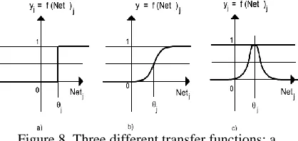
way. Depending on the outcome of this processing, the neuron j decides either to fire an output signal yj or not. The output signal (if it is triggered) can be either 0 or 1, or can have any real value between 0 and 1 (Fig. 2) depending on whether we are dealing with 'binary' or with 'real valued' artificial neurons, respectively.
The first function is a linear combination of the input variables, x1 , x2, ... xi, ... xm, multiplied with the coefficients, wji, called 'weights', while the second function serves as a 'transfer function' because it 'transfers' the signal(s) through the neuron's axon to the other neurons' dendrites. Here, we shall show now how the output, yj, on the j-th neuron is calculated. First, the net input is calculated according to equation
∑ (22)
⁄{ [ ( )]} (23)
The weights wji in the artificial neurons are the analogues to the real neural synapse strengths between the axons firing the signals.
Figure7 Comparison between the biological and artificial neuron. The circle mimicking the neuron's cell body represents simple mathematical procedure that makes one output signal yj from the set input signals represented by the multi-variate vector X.
It is important to understand that the form of the transfer function, once it is chosen, is used for all neurons in the network, regardless of where they are placed or how they are connected with other neurons. What changes during the learning or training is not the function, but the weights and the function parameters that control the position of the threshold value, qj , and the slope of the transfer function
the Net value around which the neuron is most selective.
Therefore, Figure 8 shows actually a 2-layer and a 3-layer networks with the input layer being inactive. The reader should be careful when reading the literature on ANNs because authors sometimes actually refer to the above ANNs as to the two and three-layer ones. We shall regard only the active layer of neurons as actual layer and will therefore name this networks as one and two-layer ANNs.
Figure 9.One-layer (left) and two-layer (right) ANNs. The ANNs shown can be applied to solve a
3-variable input 4-responses output problem
Fig.10.Block diagram of simulation
Fig.11.Control block diagram of simulation
5. SIMULATION RESULTS
Simulations are performed using MATLAB/SIMULINK software for tracking MPPs of the solar PV array with 7 panels, RS-P618-22 connected in series whose specifications and parameters are in Table II. The solar PV panel provides a maximum output power at a MPP with VMPP and IMPP.
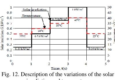
Case 1: It is assumed that the module temperature is constant, T=250C. Fig. 6 describes the variation of the solar irradiation .Then, the obtained output powers are shown as in Figs. 7-12 using the P&O, InC and improved InC algorithms, respectively under the various solar irradiations.
Fig. 12. Description of the variations of the solar irradiation and temperature
Case 2: It is assumed that both the module temperature and solar irradiation are changed, where the module temperature variation is as follows: 0s≤t<1s: T=250C; 1s≤t<2s: T=300C; 2s≤t<3s: T=350C; 3s≤t<4s: T=400C; 4s≤t≤5s: T=250C, Fig. 6 and the solar irradiation variation is as in case 1. Then, the obtained output powers are shown as in Figs. 13-14 using the P&O, InC and improved InC algorithms under the variation of both the temperature and solar irradiation.
Fig. 13 Obtained maximum output power with the P&O and improved InC algorithms under the
variation of the solar irradiation
Fig. 14. Obtained maximum output power with the InC and improved InC algorithms under the variation
of the solar irradiation Table II
Specifications And Parameters Of The Solar Pv Panel Rs-P618-22
Maximum power, 22
Voltage at 17.64
Current at 1.25
Short- circuit current, 1.34
Open-circuit voltage, 21.99
Fig. 15. Obtained maximum output power with the P&O and improved InC algorithms under both the variations of the solar irradiation and temperature
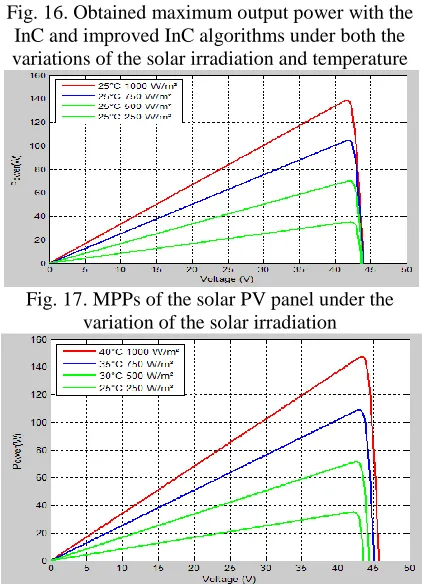
Fig. 16. Obtained maximum output power with the InC and improved InC algorithms under both the variations of the solar irradiation and temperature
Fig. 17. MPPs of the solar PV panel under the variation of the solar irradiation
Fig. 18. MPPs of the solar PV panel under both the variations of the solar irradiation and temperature
Fig. 19. Comparison of the obtained powers of the solar PV panel between strategies 1-7
Table III
Improvement Percentage Of The Obtained Powers Of The Solar Pv Panel Using The Various Control Strategies
Compariso n
Between strategies
Strategi es 2 and 1
Strategi es 3 and 1
Strategi es 4 and 1
Strategi es 5 and 1
Strategi es 6 and 1
Strategi es 7 and 1
Strategi es 3 and 2
Strategi es 5 and 4
Strategi es 7 and 6
Improveme
Table IV
Comparison Of The Obtained Powers Of The Solar Pv Panel Between Strategies 1-7
Time
(w)
(w)
(w)
(w)
(w)
(w)
(w)
07:00Am 0.16 0.48 0.72 0.51 0.54 0.76 0.8
07:30Am 0.74 1.51 1.98 1.61 1.72 2.01 2.21
08:00Am 0.76 3.14 3.25 3.50 3.57 3.29 3.63
08.30Am 1.06 3.60 3.80 4.06 4.10 4.21 4.33
09:00Am 3.30 5.19 5.23 5.23 5.92 5.18 5.96
09:30Am 4.76 7.85 8.84 8.22 8.94 9.38 10.08
10:00Am 11.48 12.86 13.26 13.05 13.75 13.04 14.00
10:30Am 11.04 13.34 13.35 13.49 14.26 13.62 14.10
11:00Am 12.43 13.92 13.78 14.30 14.89 13.96 14.55
11.30Am 12.84 14.66 14.79 14.96 15.68 14.94 15.62
12:00Pm 13:07 15.98 16.17 16.21 16.65 16.54 17.08
12:30Pm 13.53 15.58 15.95 16.18 16.23 16.17 16.83
01:00Pm 13.13 14.90 15.44 15.40 16.19 15.45 16.31
01:30Pm 10.19 11.10 11.42 10.87 12.06 11.12 12.13
02:00Pm 6.57 7.27 8.48 7.36 7.90 8.41 9.00
02:30Pm 5.58 9.19 10.18 8.76 9.98 10.58 11.50
03:00Pm 5.01 6.70 7.64 6.40 7.28 7.75 8.62
03.30pm 4.37 5.60 5.70 5.36 6.25 5.73 6.20
04:00pm 3.15 4.22 5.21 4.14 4.71 5.21 5.67
04:30Pm 2.84 3.66 4.28 3.51 4.08 4.47 4.66
05:00Pm 1.89 2.98 3.94 3.23 3.32 4.03 4.28
Total 137.91 173.72 183.42 176.35 188.03 185.86 197.58
6. CONCLUSION
In this paper, an improvement of the conventional InC algorithm has been proposed for tracking MPPs of a solar PV panel, known as an improved InC algorithm. To ensure good tracking ability and disturbance rejection, ANN controller is
developed. The tracking ability of the MPP and obtained output power by the improved InC algorithm are always better than those using the P&O and conventional InC algorithms, especially under the rapid variation condition of the temperature and
solar irradiation. In ANN is non-paramateric
statistic basic control action and improve the
efficiency. The results acquired during the simulations it indicate that the proposed control system is capable to track MPP with performance, simplicity and fast response. This paper proposes an improved InC algorithm for tracking a MPP on the V-I characteristic of the solar PV panel using ANN controller. By using the simulation results we can conform the proposed algorithm is effective and validated compared with that of using the conventional algorithms.
REFERENCES
[1] R. Faranda and S. Leva, “Energy comparison of MPPT techniques for PV systems,” Trans. Power Syst., vol. 3, no. 6, pp. 446-455, 2008.
[2] X. Jun-Ming, J. Ling-Yun, Z. Hai-Ming and Z. Rui, “Design of track control system in PV,” IEEE Int. Conf. Software Engineering and Service Sciences, ICSESS2010, pp. 547-550, 2010.
[3] Z. Bao-Jian, G. Guo-Hong and Z. Yan-Li, “Designment of automatic tracking system of solar energy system,” 2nd Int. Conf. Industrial Mechatronics and Automation, ICIMA2010, pp. 689-691, 2010.
[4] W. Luo, “A solar panels automatic tracking system based on OMRON PLC,” Proc. 7th Asian Control Conf., pp. 1611-1614, 2009.
[5] W. Chun-Sheng, W. Yi-Bo, L. Si-Yang, P. Yan-Chang and X. Hong- Hua, “Study on automatic sun-tracking technology in PV generation,” Third Int. Conf. Electric Utility Deregulation and Restructuring and Power Technologies, DRPT2008, pp. 2586-2591, 2008.
[6] C. Alexandru and C. Pozna, “Different tracking strategies for optimizing the energetic efficiency of a photovoltaic system,” Int. Conf. Automation, Quality and Testing, Robotics, pp. 434-439, 2008.
[7] R. Sridhar, S. Jeevananthan, N. T. Selvan and P. V. SujithChowdary, “Performance improvement of a photovoltaic array using MPPT P&O technique,” Int. Conf. Control and Comput. Technol., pp. 191-195, 2010.
[8] N. M. Razali and N. A. Rahim, “DSP-based maximum peak power tracker using P&O algorithm,” IEEE First Conf. Clean Energy and Technol., pp. 34-39, 2011.
[9] L. Chun-Xia, L. Li-qun, “An improved perturbation and observation MPPT method of photovoltaic generate system,” 4th IEEE Conf. Ind. Electron. and Appl., ICIEA2009, pp. 2966-2970, 2009