Abstract—In the present work, a compact size, dual-band antenna is proposed for WLAN/WiMAX/LTE 2500/DMB applications. The designed antenna is fed by a 50 Ω coplanar line. The radiating component of the composed antenna consists of radiating strips with half hexagonal and vertical rectangular shapes and square-shaped ground plane which are printed on the same layer. The overall size of the antenna substrate is only 10×24×1.6 mm3. The simulated and measured results of the proposed antenna show that it operates in the frequency range from 2.5 GHz to 2.75 GHz and 5.0 GHz to 6.7 GHz, respectively.
1. INTRODUCTION
Long-Term Evolution (LTE) 2500, Wireless Local Area Network (WLAN) IEEE 802.11 a/b/g and Worldwide Interoperability for Microwave Access (WiMAX) IEEE 802.16 are three popular advanced communication standards meant for point to point high-speed data communication applications. According to Federal Communications Commission (FCC) guidelines, each communication protocol is designated with a band of frequencies for different regions of the world, such as IEEE 802.11 a (5.150–5.350 GHz and 5.725–5.825 GHz) for WLAN, 5.5 GHz band (5470–5725 MHz) for Europe LAN/HIPERLAN2, 2.5 GHz band (2500–2690 MHz) for LTE 2500 and WiMAX, 2.6 GHz band (2600– 2660 MHz) for digital multimedia broadcasting (DMB) system applications. In practice, if the deployed inbuilt antenna in a communication system is not capable of operating at these multiple frequencies, then the product developer/end user needs to modify or replace existing antenna element with advanced versions. Hence, to address these problems, researchers around the world focus on the design of electrically small multiband antennas with wide impedance bandwidth characteristics. Distinct shaped antennas with dual [1–6] and triple operating bands [7–12] with different substrates have been reported in the literature, which are fed by microstrip [4–6, 9, 10, 20] and coplanar waveguide (CPW) [1–3, 7, 8].
A smart feeding configuration, ACS, which adopts the principle of Coplanar Waveguide (CPW) feeding has been recently described in [11–19, 21–24]. These antennas are generally smaller than simple coplanar waveguide (CPW)-fed antenna. Fig. 1 shows a basic ACS-fed antenna which has one-half of the ground plane so that it has a smaller size than a simple coplanar waveguide CPW-fed antenna [11– 19]. Most of the reported printed antennas (tri-band and dual-band) are larger in size and only operate at limited frequency in WLAN/WiMAX bands. For example, an antenna reported in [11] is a tri-band antenna with large size (299 mm2) and does not cover 2.5/5.5 GHz WiMAX and 5.8 GHz WLAN application bands, Similarly, the antenna in [24] is large in size (318 mm2) and does not support 5.2 GHz WLAN and 2.5 GHz LTE band. However, the printed antenna reported in [23] is relatively small, but it is not capable of covering 5.8 GHz WLAN and 5.5 GHz WiMAX bands. Hence, in this research, a dual wide band monopole antenna is presented. The designed antenna comprises two radiating arms, and it
Received 3 August 2017, Accepted 14 September 2017, Scheduled 26 September 2017 * Corresponding author: Arvind Kumar ([email protected]).
1 Department of ECE, Kautilya Institute of Technology and Engineering, Jaipur 302022, India.2Velagapudi Ramakrishna Siddhartha
(a) (b)
Figure 1. Overview of coplanar waveguide (CPW) and ACS (Asymmetric coplanar strip) methods (s,
s1 and s2 are denoting to the coaxial feed location).
generates two operating bands from 2.5 GHz to 2.75 GHz and from 5.0 GHz to 6.7 GHz as the first and second bands, respectively. This developed antenna is suitable to operate in 2.5 GHz WLAN/DMB, 2.5/5 GHz WiMAX and LTE 2500 frequency bands.
2. ANTENNA DESIGN
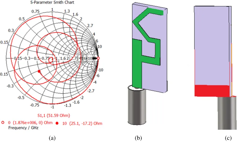
The CST MWS 3D model, geometry and fabricated prototype photograph of the proposed half hexagonal ACS fed antenna are shown in Fig. 2. The corresponding Smith chart is given in Fig. 3(a). As highlighted in the literature, in order to show the advantages and benefits of the proposed ACS feeding concept over other feeding techniques (such as microstrip and CPW), the proposed half hexagonal geometry performance is validated with microstrip configuration without changing any parameter dimensions in the design. Fig. 2(a) and Figs. 3(b), (c) illustrate the configuration of the dual-band ACS and microstrip feed monopole antennas, which are printed on a 10 mm×24 mm FR4 substrate of 1.6 mm thickness, with loss tangent tanδ of 0.002 and permittivity 4.4. In both the feeding techniques, antenna radiating elements are the same with rectangular shape, open half hexagonal shape radiators with a square ground plane as depicted in Figs. 3(b), (c). Both the feeding techniques are excited by a 50 Ω feed line, and its simulated frequency versus VSWR plots is shown in Fig. 4. It can be clearly observed that wide impedance bandwidth (second operating band) is achieved with ACS technique compared with microstrip feeding. The parameter values used in the antenna geometry are shown in Table 1. In the design process, the length of the open half hexagon- and rectangle-shaped radiating strips is chosen approximately equal to half of the wavelength (λ/2) at the desired operating frequency. The resonance frequency (fr) of the half wavelength resonator is given by Equation (1).
fr≈ Vc
2
εr+ 1 2
, (1)
z0= 60
√ε
eff K(κ)
K(κ1) (2)
(a) (b) (c)
Figure 2. (a) Geometry of the compact tunable meandered ACS fed antenna. (b) Proposed antenna 3D model. (c) Fabricated prototype antenna photograph.
(a) (b) (c)
Figure 3. (a) Impedance smith chart of the presented compact tunable half hexagonal ACS fed dual band antenna. (b) Microstrip fed antenna 3D model with SMA connector (Top view). (c) Microstrip fed antenna 3D model (Bottom view).
K(κ)
K(κ1) (the elliptical integral of first kind) is represented mathematically as:
K (κ) K (κ1) =
⎧ ⎪ ⎪ ⎪ ⎪ ⎪ ⎨ ⎪ ⎪ ⎪ ⎪ ⎪ ⎩ π
ln2(1+ √
κ1)
(1−√κ1)
0≤κ≤ √1 2
1
π ln2(1+ √
κ) (1−√κ)
1
√
2 ≤κ≤1
(3)
Figure 4. VSWR corresponding to ACS fed antenna and Microstrip fed antenna.
(a) (b) (c) (d)
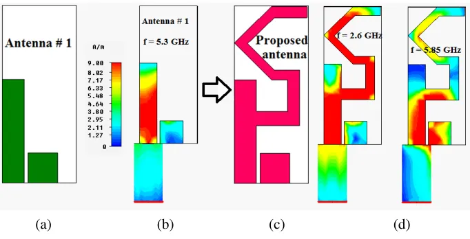
Figure 5. Surface current distribution characteristics of the presented compact tunable ACS fed semi hexagonal multiband antenna antenna at 2.6 GHz, 5.3 GHz and 5.85 GHz.
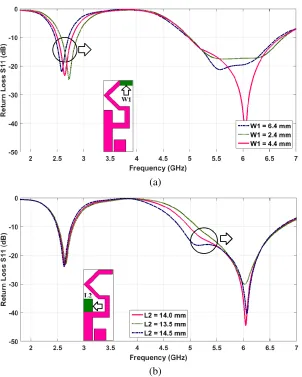
between 5 to 6 GHz is achieved with a simple rectangular strip attached to the ACS feedline (Antenna 1). To generate one more operating band at lower frequency, a half wavelength open half hexagonal radiating strip is added to Antenna 1 (Figs. 5(c) and (d) and Fig. 6). The design and optimization procedure of compact meandered shape ACS-fed antenna is carried out by CST MWS software. For better understanding about the independent tuning property of the proposed semi-hexagonal patch antenna, a detailed parametric study is carried out by using CST MWS toolbox, and its frequency versus return loss plots are given in Figs. 7(a) and (b).
Table 1. Half hexagonal shape ACS fed antenna geometry values.
Parameters L W6 W L2 W3 g1 L5 g4 W2
Value (mm) 24 4 10 4.3 2 1.9 4 1.3 2.2
Parameters g2 W1 g3 L3 W5 L4 W4 L1 G
Figure 6. S11 corresponding to the evolutionary stages of compact tunable meandered ACS fed dual band antenna.
(a)
(b)
Figure 8. Semi hexagonal ACS fed antenna measured and simulated return loss results with fabricated prototype phograph.
by considering the effect of coaxial cable with SMA connector having dimensions corresponding to the actual connector and cable used for measurements. From Fig. 8, it can be observed that a similar return loss result can be observed with and without considering cable connected to SMA connector in the simulation.
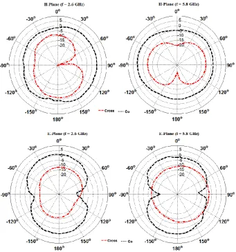
In the result, a little discrepancy is found between measured and simulated results due to the soldering, fabrication tolerance, calibration cable effects, etc. Measurement of far-field radiation pattern is executed in an anechoic chamber where a standard double-ridged horn antenna is utilized as a reference antenna. In Fig. 9, it is figured out that dumb-bell shape (bidirectional) and nearly omnidirectional patterns are achieved inE-plane andH-plane. From this figure, it is manifested that measured radiation pattern is leaned because of the asymmetrical ground plane and alignment errors. The co-polarization level positions are maximum compared to cross polarization in each stage of E-plane and H-plane.
Figure 11. Dual operating peak gains of the presented compact tunable half hexagonal ACS fed antenna.
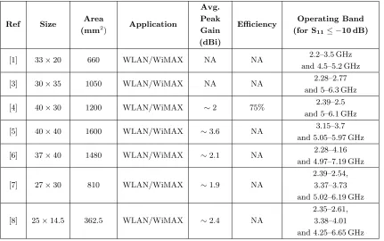
Table 2. Proposed compact ACS fed antenna performance comparison with literature.
Ref Size Area
(mm2) Application
Avg. Peak Gain (dBi)
Efficiency Operating Band (for S11≤ −10 dB)
[1] 33×20 660 WLAN/WiMAX NA NA 2.2–3.5 GHz
and 4.5–5.2 GHz
[3] 30×35 1050 WLAN/WiMAX NA NA 2.28–2.77
and 5–6.3 GHz
[4] 40×30 1200 WLAN/WiMAX ∼2 75% 2.39–2.5
and 5–6.1 GHz
[5] 40×40 1600 WLAN/WiMAX ∼3.6 NA 3.15–3.7
and 5.05–5.97 GHz
[6] 37×40 1480 WLAN/WiMAX ∼2.1 NA 2.28–4.16
and 4.97–7.19 GHz
[7] 27×30 810 WLAN/WiMAX ∼1.9 NA
2.39–2.54, 3.37–3.73 and 5.02–6.19 GHz
[8] 25×14.5 362.5 WLAN/WiMAX ∼2.4 NA
and 4.76–6.55 GHz
[15] 13.75×26 357.5 WLAN/WiMAX ∼3.2 76% 2.40–2.60 GHz
and 3.2–6.0 GHz
[16] 13.4×22.7 304.2 WLAN/WiMAX ∼2.9 NA 2.45–2.7 GHz
and 3.9–6.0 GHz
[17] 20×22 440 WLAN/WiMAX ∼2.1 NA
2.3–2.5 GHz, 3.4–5.85 GHz and 7.7–8.4 GHz
[18] 18×22 396 WLAN/WiMAX ∼2.8 87% 1.8–2.2 GHz
and 3.0–7.6 GHz
[19] 22.1×12 265.2 WLAN/WiMAX ∼2.2 NA
2.37–2.53 GHz, 3.37–3.71 GHz and 4.93–6.35 GHz
[20] 34×28 952 WLAN/WiMAX ∼3.1 90% 2.37–3.98 GHz
and 4.95–5.94 GHz
[21] 26.5×12 318 WLAN/WiMAX ∼1.95 NA
2.32–2.53 GHz, 3.22–3.64 GHz and 5.53–5.98 GHz
[22] 32×12 384 WLAN/WiMAX ∼1.85 NA
2.36–2.70 GHz, 3.35–2.74 GHz and 5.01–6.12 GHz Propo
sed 24×10 240
LTE/WLAN/
WiMAX/DMB ∼2.95 85%
2.5–2.75 GHz and 5.0–6.7 GHz
4. CONCLUSION
straight strips and two∩-shaped slots for WLAN/WiMAX applications,” Microwave and Optical Technology Letters, Vol. 54, No. 6, 1466–1469, 2012.
6. Yoon, J. H. and G. S. Kil, “Compact monopole antenna with two strips and a rectangular-slit ground plane for dual-band WLAN/WiMAX applications,” Microwave and Optical Technology Letters, Vol. 54, No. 7, 1559–1566, 2012.
7. Hua, M. J., P. Wang, Y. Zheng, and S. L. Yuan, “Compact tri-band CPW-fed antenna for WLAN/WiMAX applications,” Electronics Letters, Vol. 49, No. 18, 1118–1119, 2013.
8. Li, Y. and Q. Feng, “A compact tri-band monopole antenna with metamaterial loaded for WLAN/WiMAX applications,”Journal of Electromagnetic Waves and Applications, Vol. 27, No. 6, 772–782, 2013.
9. Zhang, L., B. Chen, Y. C. Jiao, and Z. B. Weng, “Compact triple-band monopole antenna with two strips for WLAN/WiMAX applications,” Microwave and Optical Technology Letters, Vol. 54, No. 11, 2650–2653, 2012.
10. Chawanonphithak, Y., and C. Phongcharoenpanich, “Design of triple-band antenna using S-shaped patch fed by cross strip line for WLAN and WiMAX applications,” IEE J. Transactions on Electrical and Electronic Engineering, Vol. 10, No. 5, 491–497, 2015.
11. Naidu, P. V. and A. Kumar, “A novel ACS fed multi band antenna loaded with mirrored S and L shaped strips for advanced portable wireless communication applications,” Microsystem Technologies, 1–9, 2017.
12. Naidu, P. V. and A. Kumar, “Design and development of triple band ACS fed antenna with M and rectangular shaped radiating branches for 2.45/5 GHz wireless applications,” Microsystem Technologies, 1–8, 2017.
13. Li, Y., W. Li, and Q. Ye, “A compact asymmetric coplanar strip-fed dual-band antenna for 2.4/5.8 GHz Wlan applications,”Microwave and Optical Technology Letters, Vol. 55, No. 9, 2066– 2070, 2013.
14. Li, B., Z.-H. Yan, and T.-L. Zhang, “Triple-band slot antenna with U-shaped open stub fed by asymmetric coplanar strip for WLAN/Wimax applications,”Progress In Electromagnetics Research Letters, Vol. 37, 123–131, 2013.
15. Naidu, P. V. and A. Malhotra, “Design & analysis of miniaturized asymmetric coplanar strip fed antenna for multi-band WLAN/WiMAX applications,” Progress In Electromagnetics Research C, Vol. 57, 159–171, 2015.
16. Naidu, P. V., A. Malhotra, and R. Kumar, “A compact ACS-fed dual-band monopole antenna for LTE, WLAN/WiMAX and public safety applications,”Microsystem Technologies, 1–8, 2015, DOI: 10.1007/s00542-015-2562-z.
ended slots for WLAN/WiMAX applications,”Journal of Electromagnetic Waves and Applications, Vol. 28, No. 9, 1109–1117, 2014.