Western University Western University
Scholarship@Western
Scholarship@Western
Electronic Thesis and Dissertation Repository
10-1-2012 12:00 AM
Development of 3-D Neutronic Kinetic Model and Control for
Development of 3-D Neutronic Kinetic Model and Control for
CANDU Reactors
CANDU Reactors
Lingzhi Xia
The University of Western Ontario
Supervisor Jin Jiang
The University of Western Ontario
Graduate Program in Electrical and Computer Engineering
A thesis submitted in partial fulfillment of the requirements for the degree in Doctor of Philosophy
© Lingzhi Xia 2012
Follow this and additional works at: https://ir.lib.uwo.ca/etd
Part of the Electrical and Computer Engineering Commons
Recommended Citation Recommended Citation
Xia, Lingzhi, "Development of 3-D Neutronic Kinetic Model and Control for CANDU Reactors" (2012). Electronic Thesis and Dissertation Repository. 898.
https://ir.lib.uwo.ca/etd/898
Development of 3-D Neutronic Kinetic
Model and Control for CANDU
Reactors
(Thesis format: Monograph)
By
Lingzhi Xia
Graduate Program in Electrical
and Computer Engineering
A thesis submitted in partial fulfillment
of the requirements for the degree of
Doctor of Philosophy
School of Graduate and Postdoctoral Studies
The University of Western Ontario
London, Ontario
THE UNIVERSITY OF WESTERN ONTARIO
SCHOOL OF GRADUATE AND POSTDOCTORAL STUDIES
CERTIFICATE OF EXAMINATION
Chief Advisor Examining Board
__________________________
Dr. Jin Jiang Dr. Eleodor Nichita
Advisory Committee __________________________
__________________________ Dr. Sree Ram Valluri
Dr. Ken McIsaac __________________________
__________________________ Dr. Ken McIsaac
Dr. Amirnaser Yazdani __________________________
Dr. Lyndon J. Brown
The thesis by
Lingzhi Xia
Entitled
Development of 3-D Neutronic Kinetic Model and
Control for CANDU Reactors
is accepted in partial fulfillment of the
requirements for the degree of
Doctor of Philosophy
Date: _______________ __________________________
ABSTRACT
The development of a three dimensional (3-D) neutronic kinetic modeling process aiming
at control system design for CANadian Deuterium Uranium (CANDU) reactors is carried
out in this thesis using a modal synthesis method. In this method, the reactor
space-time-dependent neutron flux is synthesized by a time-weighted series of
precalculated neutron flux modes. These modes are eigenfunctions of the governing
neutron diffusion equation at reference steady-state operating conditions. The Xenon
effect has also been considered. Special attention has been paid to compare the
performance of the developed 3-D model with that of a traditional coupled point kinetic
model. The 3-D reactor model is implemented by MATLAB/SIMULINK software
environment. A nondimensionalized SIMULINK representation of the reactor model is
established.
The performance of the developed 3-D reactor neutronic kinetic model is then evaluated
in a closed-loop environment with the help of a CANDU reactor regulating system (RRS)
simulation platform. The dynamic behavior of the reactor model in a practical
load-following mode has also been examined. The accuracy of the model has been
validated against actual plant measurements under transient conditions. Through the
analysis and simulation studies, it has convincingly demonstrated that the developed 3-D
reactor model has significant advantages over the traditional coupled point kinetic model
in terms of the improved accuracy and higher resolution in modeling the reactor internal
flux behavior. Furthermore, using Graphic User Interface (GUI) techniques a
user-friendly software package for the RRS simulation platform is developed.
Based on the 3-D reactor model and identified deficiencies of existing RRS’ functions, an
advanced 3-D reactor power distribution control is proposed and investigated.
reactor model is evaluated in a closed-loop RRS environment. Using the feedback control
law, a newly designed control strategy tries to suppress the effects of high order neutron
flux modes and to emphasize behaviors of the dominant mode – the fundamental flux
distribution adopted by the nominal design. Thereby, the 3-D power distribution shape
during transients is optimally maintained closer to the nominal design shape than by the
traditional RRS. The benefits of 3-D power distribution include not only the improved
economical operation, but also improved safety as the uncertainties and the uneven power
distribution are reduced. These have been confirmed by extensive simulation studies on
Regional Overpower Protection (ROP) detectors’ flux transients during load following
processes.
Keywords: CANDU, 3-D, neutronic kinetic model, RRS, reactor control
ACKNOWLEDGMENT
I wish to express my sincere acknowledgement to my thesis supervisor, Dr. Jin Jiang, for
his creative inspirations, guidance and encouragements throughout my academic program.
His technical and philosophical advice, financial support and friendship are essential
factors to the success of this study and are greatly appreciated.
I have certainly benefitted from continued technical supports from Dr. John C. Luxat at
McMaster University. His generous support and friendship will always be appreciated
and treasured.
I would like to express my deepest gratitude to my parents and other family members for
their eternal loving and supports to me.
I appreciate the mutual encouragement and support with my best friend, Drew J. Rankin,
through all these years of study together at Western University. Sincere appreciation is
extended to other CIE group members, such as Dr. Xinghong Huang, Dr. Xiang Yu, Dr.
Qingfeng Li, Jianping Ma, Peiwei Sun etc. Special acknowledgement is expressed to a
previous group member, Dr. Hooman Javidnia.
Special appreciation goes to Prof. Jianmin Zhang at Xi’an Jiaotong University of China,
Mr. Zhiliang Meng in Qinshan-III, and Dr. Wei Shen in Candu Energy Inc. I also would
like to thank the Institute for Energy Technology (IFE) in Halden, Norway to share their
Core Data Viewer (CDV) program for data display used in this thesis.
I would like to acknowledge both the financial and technical supports from: Atomic
Energy Canada Limited (AECL), Natural Science and Engineering Research Council of
Canada (NSERC), University Network of Excellence in Nuclear Engineering (UNENE),
TABLE OF CONTENTS
ABSTRACT ...iii
ACKNOWLEDGMENT ... v
TABLE OF CONTENTS ... vi
LIST OF FIGURES ... xi
LIST OF TABLES ... xvi
ABBREVIATIONS AND NOMENCLATURE ... xvii
I Introduction ... 1
1.1 Introduction to CANDU reactor ... 1
1.2 Background and motivations ... 3
1.3 Scope and methodology ... 9
1.4 Contributions ... 13
1.5 Organization of the thesis ... 14
II Reactor neutronic kinetics ... 16
2.1 Introduction ... 16
2.2 Reactor power and neutron flux ... 18
2.3 Prompt and delayed neutrons ... 19
2.4 Reactivity feedback and control ... 21
2.5.1 Neutron diffusion approximation of the reactor kinetics ... 25
2.5.2 Point kinetic equation ... 29
2.5.3 Numerical methods for solving the space-time diffusion equation ... 31
2.6 Summary... 40
III 3-D neutronic kinetic model of CANDU reactors ... 41
3.1 Brief description of CANDU-6 assembly ... 41
3.2 The diffusion description of CANDU reactor kinetics ... 45
3.3 Modal modeling of CANDU reactors ... 48
3.3.1 3-D neutron flux harmonic modes in CANDU reactors ... 49
3.3.2 Modeling procedure for 3-D modal representations ... 55
3.4 Comparison of coupled point kinetic and modal synthesis models ... 58
3.4.1 Modeling of CANDU reactor kinetics by a coupled point kinetic method ... 58
3.4.2 Comparison of two reactor models ... 60
3.5 Vectorization and implementation within a SIMULINK environment ... 65
3.6 Initialization and steady-state solution ... 70
3.7 3-D neutron flux distribution at steady-state condition ... 72
3.8 Summary... 79
IV Simulation of the CANDU reactor regulating system ... 80
4.1.1 Power measurement and calibration ... 85
4.1.2 Demand power ... 86
4.1.3 Reactivity control devices ... 87
4.1.4 Other routines ... 89
4.2 MATLAB/SIMULINK simulation platform of the RRS ... 90
4.2.1 Matrix and vector representation ... 91
4.2.2 Reactivity control principles ... 94
4.2.3 Efficient implementation of the RRS simulation platform ... 98
4.3 Simulations of power maneuvering operations ... 103
4.4 Evaluation of 3-D reactor model under load following operation ... 108
4.4.1 Reactor power transients ... 108
4.4.2 Water level transient in liquid zone units... 112
4.4.3 Xenon dynamics... 114
4.4.4 Neutron flux dynamics within regional overpower protection detectors ... 115
4.4.5 Core neutron flux distribution during transients ... 119
4.5 CANDU RRS Graphical User Interface (GUI) ... 124
4.6 Summary... 127
kinetics ... 128
5.1 Brief introduction of the power distribution control problem ... 128
5.2 Control oriented kinetics models for CANDU reactors ... 131
5.2.1 Linearization of the reactor model ... 131
5.2.2 Validation of the linearized model ... 135
5.3 Control of power distribution in the reactor ... 136
5.4 Feedback control system design for the 3-D power distribution control ... 140
5.5 Performance evaluation of the power distribution control ... 142
5.5.1 Simulations of Power Regulation based on Linear and Nonlinear Reactor Models 142 5.5.2 3-D power distribution of the closed-loop reactor system ... 146
5.5.3 Power transients of ROP detectors under the new control strategies ... 149
5.6 Summary... 152
VI Conclusions and suggestions for future works ... 154
6.1 Conclusions ... 154
6.2 Recommendation for future works ... 155
References ... 157
Appendix A... 167
Appendix B ... 174
Appendix C-2 ... 185
Appendix D... 186
Appendix E ... 189
Appendix F ... 197
Appendix G... 198
Appendix H... 211
LIST OF FIGURES
Fig. 3.1 Diagram of CANDU reactor assembly [56] ... 42
Fig. 3.2 End view of reactor showing principal calandria dimensions and fuel channels [57] ... 44
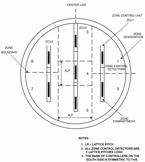
Fig. 3.3 Positions of zone control detectors in half core with respect to zone compartments [57]... 45
Fig. 3.4 The coordinate for CANDU reactor modeling, r=(x,y,z) ... 48
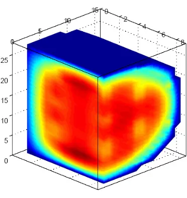
Fig. 3.5 An illustrative diagram of core modeling using point kinetic equations ... 64
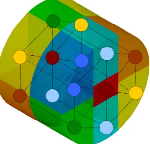
Fig. 3.6 An example of flux distribution modeled by the modal synthesis method ... 65
Fig. 3.7 Block diagram of the reactor model using modal synthesis method ... 69
Fig. 3.8 A generic block diagram for implementation of the reactor model ... 70
Fig. 3.9 Neutron flux distribution within the first layer (end face) along the axial direction ... 74
Fig. 3.10 Neutron flux distribution within the second layer along the axial direction ... 74
Fig. 3.11 Neutron flux distribution within the third layer along the axial direction ... 75
Fig. 3.12 Neutron flux distribution within the fourth layer along the axial direction ... 75
Fig. 3.13 Neutron flux distribution within the fifth layer along the axial direction ... 76
direction ... 76
Fig. 3.15 Neutron flux distribution along a fuel channel next to the central axis ... 77
Fig. 3.16 reactor power distribution by a modal synthesis model (reactor bulk power is 1.0 FPU; (a) - the sixth plane; (b) - the fourth plane; (c) - the second plane and (d) - the end plane) ... 78
Fig. 4.1 CANDU RRS block modules [55] ... 83
Fig. 4.2 Block diagram of RRS in CANDU reactors ... 91
Fig. 4.3 Block diagram of a flux bulk control loop ... 95
Fig. 4.4 MATLAB/SIMULINK simulation platform for the CANDU reactor regulating system (RRS) ... 99
Fig. 4.5 Bulk power responses based on coupled point kinetic and modal synthesis models (the reactor power is reduced from 1.0 FPU to 0.9 FPU at 0.1FPU/s) ... 104
Fig. 4.6 Simulation result of reactor power spatial control (1.0 FPU – 0.9 FPU, at a rate of 1%FP/second) ... 105
Fig. 4.7 LZU water level transient simulation result (Xenon effect excluded) ... 106
Fig. 4.8 LZU water level transient simulation result (Xenon effect included) ... 106
Fig. 4.9 Simulation result of Xenon dynamic reactivity ... 107
Fig. 4.11 Changes in reactor bulk power in a load-following process ... 109
Fig. 4.12 Changes in zonal normalized powers during load-following process using modal synthesis method ... 110
Fig. 4.13 Comparison of LZU average water levels for load-following process ... 112
Fig. 4.14 Simulation results of 14 LZU water level variations for load following transient ... 114
Fig. 4.15 Comparison of Xenon dynamic reactivity for load following operation ... 115
Fig. 4.16 ROP detector location for SDS1 within the center cross section of the core ... 117
Fig. 4.17 Simulation results of the neutron flux varying within selected ROP detectors for load following process ... 118
Fig. 4.18 Simulation results of Xenon amplitudes for flux modes 2 and 3 ... 119
Fig. 4.19 Schematic representation of flux modes 2 and 3 for the CANDU reactor ... 119
Fig. 4.20 The relative position of the fourth layer within the CANDU reactor core ... 120
Fig. 4.21 Neutron flux distribution at the fourth layer along the z-direction (reactor power is 1.0 FPU) ... 120
Fig. 4.22 Neutron flux distribution at the fourth layer along the z-direction (reactor power is 0.95 FPU) ... 121
Fig. 4.24(a) Neutron flux distribution along the z-axis at different power levels ... 123
Fig. 4.24(b) Neutron flux distribution along the x-axis within the central plane at different
power levels ... 123
Fig. 4.24(c) Neutron flux distribution along the y-axis within the central plane at different
power levels ... 124
Fig. 4.25(a) MATLAB GUI for CANDU RRS simulation platform ... 126
Fig. 4.25(b) 3-D flux distribution module of the CANDU RRS GUI ... 126
Fig. 5.1 Simulation results of reactor dynamics with two reactor models using RRS’
simulation ... 136
Fig. 5.2 A block diagram of the state-feedback design for CANDU reactor power
distribution control... 141
Fig. 5.3 The closed-loop dynamic system responses of the designed control strategy under
two reactor models ... 144
Fig. 5.4 Variations of 14 zonal powers under linearized and nonlinear reactor models.... 145
Fig. 5.5 Simulation results of 14 zone water levels using the newly designed control
strategy ... 146
Fig. 5.6 Normalized power distributions of the fourth layer of the core at 4,620 s under two
different control schemes (a) RRS control, and (b) new control scheme. ... 147
Fig. 5.7 Simulation results of the power dynamics within selected ROP detectors
Fig. 5.8 Simulation results of Xenon amplitudes for flux modes 2 and 3 implemented by
3-D control strategy ... 150
Fig. 5.9 Simulation results of 7E ROP detector power transients implemented by RRS and the new control strategy ... 152
Fig. C-2 SIMULINK module of reactor kinetic modal modeling ... 185
Fig. D-1 Files of CANDU RRS GUI software package ... 186
LIST OF TABLES
Table 2.1 The parameters of delayed neutron precursors from U235 thermal-fissions [33] .... 20
Table 3.1 Gross features of the CANDU-6 reactor core [57] ... 43
Table 3.2 Neutron flux harmonic modes ψi(r) (CANDU-6 type), i = 1 to 13 and their respective characteristics ... 51
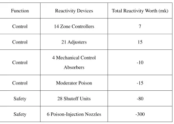
Table 3.3 Reactivity devices with their total reactivity worth ... 53
Table 4.1 Reactivity worth and maneuvering rates of reactivity control devices ... 89
Table 4.2 Normalized power distributions at eight time instances (in FPU) ... 111
Table 4.3 Relative changes in actual power distributions at eight time instances (in MW) ... 111
Table 4.4 Response errors of the average levels for both reactor models ... 113
ABBREVIATIONS AND NOMENCLATURE
Abbreviations
3-D Three-Dimensional
AECL Atomic Energy Canada Ltd.
CANDU CANadian Deuterium Uranium
CATHENA Canadian Algorithm for THErmalhydraulic Network Analysis
CDV Core Data Viewer
DCC Digital Control Computer
ELOCA Element Loss-Of-Coolant Accident
FPU Full Power Unit
FLU Full Level Unit
GUI Graphic User Interface
LOCA Loss of Coolant Accident
LZU Liquid Zone Unit
LQR Linear Quadratic Regulator
NPP Nuclear Power Plant
ODE Ordinary Differential Equation
PDE Partial Differential Equation
PLD Programmable Logic Device
PHWR Pressurized Heavy Water Reactor
RFSP Reactor Fuelling Simulation Program
RRS Reactor Regulating System
ROP Reactor Overpower Protection
SDS1 Shutdown System No. 1
SDS2 Shutdown System No. 2
Nomenclature
Α the coupling volume integration matrix of all the modes
p
Α a matrix containing first nine columns of Α
2
B the reactor curvature
9 14
B× a constant matrix of controller signal
blkdiag block diagonal matrix
Cj the concentration of the delayed neutron precursor
Cij(t) the amplitude of the delayed neutron group j for mode i
D the diffusion length
diag diagonal matrix
R
E energy release per fission
( , )
F r t neutron production operator
I the Iodine I135 concentration
Ii(t) the amplitude of Iodine for mode i
I vector of Iodine amplitudes
J the optimum performance index – quadratic cost function
keff effective multiplication factor
kex excess multiplication factor
ki eigenvalue associated to the ith flux mode
K, Ki the designed control system gains
lk *
the prompt neutron generation time for kthmode
ni(t) the amplitude of the thermal neutron flux for mode i
N average nucleus number of fission materials in core
N vector of neutron flux amplitudes
P reactor power
P vector of delayed neutron precursor amplitudes
3D
P 3-D normalized core pin power
r
P the designed power maneuvering set-point as the function of time
x
Q ,Qy non-negative definite matrices
r the spatial vector in core
SCK
L
ℜ matrix of the modal coupled reactivity induced by the movement of the
reactivity devices
X
ℜ matrix of the dynamic reactivity feedback of the Xenon concentration
( , )
R r t neutron loss operator
R positive definite matrix
S the external neutron sources
T the time variable
U 14 water levels in liquid zone controllers
v the neutron velocity
V the reactor volume
x state variable of the reactor model
X the Xenon concentration
Xs the referenced Xenon concentration
Xi(t) the amplitude of Xenon for mode i
Xis the referenced amplitude of Xenon for mode i
X vector of Xenon amplitudes
y output of the control system
Greek letters
φ the prompt neutron flux
condition
α the reactivity coefficient under different conditions
p
χ the fission neutron spectrum
p
ν the fission yield
ψi(r) the normalized neutron flux mode i
λj the decay constant of the delayed neutron group j
βj the fission fraction of the delayed neutron group j
β the total fission fraction of the delayed neutron groups
γI the direct fission yield of I135
γX the direct fission yield of Xe135
υ the fission yield
λI the Iodine decay constant
λX the Xenon decay constant
σX the Xenon microscopic absorption cross-section
f
σ microscopic fission cross-section
) (r
δ spatial reactivity perturbation area
sck
ρ the subcritical reactivity of the flux mode k
ki
ρ the modal cross coupling reactivity between kth and mth modes
ρki X
the modal reactivity reflecting Xenon effect build-up
f
φ the flux-squared weighted fundamental mode
a
Σ the macroscopic absorption cross-section
s
Σ the macroscopic scattering cross-section
f
Σ the macroscopic fission cross-section
∇ the Laplace operator
55,n
Θ the modal reactivity regarding the water level in the nth zone at 0.55 FLU
25,n
Θ the modal reactivity regarding the water level in the nth zone at 0.25 FLU
Subscripts
i neutron flux mode number
j group number of delayed neutron precursors
M the number of the selected modes
I Introduction
1.1 Introduction to CANDU reactor
The CANadian Deuterium Uranium (CANDU) reactor is a reactor of unique design that
utilizes natural uranium as fuel and heavy water as moderator and coolant [1]. This
reactor achieves substantial financial savings due to the absence of fuel enrichment costs.
However, a chemical plant is required to produce the quantities of heavy water.
The original CANDU designer is AECL (Atomic Energy of Canada Limited), a federal
crown corporation created in 1952. Over 150 private companies in Canada supply
components for the CANDU system. As of October 1, 2011, responsibility for all
commercial CANDU design, maintenance services and marketing was transferred to the
Mississauga, Ontario-based Candu Energy Inc., a wholly owned subsidiary of
Montreal-based engineering firm SNC Lavalin.
CANDU-6 is a 700 MW nuclear power reactor. The first CANDU-6 plant went into
service in the early 1980s, and the design continues to evolve to maintain superior
technology and performance. In Canada, CANDU reactors are used to supply power in
Ontario, Quebec and New Brunswick. The Pickering facility east of Toronto on Lake
Ontario and the Bruce facility northwest of Toronto have 8 reactors per site. AECL has
also provided CANDU reactors to utilities in Argentina, India, South Korea, Pakistan,
The thermal efficiency of a CANDU reactor plant is approximately 29%, but the CANDU
reactor uses a larger fraction of U-235 in uranium ore than other reactors and also makes
better use of the U-238 to Pu-239 conversion process to extend fuel burnup[2]. Moreover,
statistics show that, among large reactors, CANDU reactors have outstanding reliability
records, with annual capacity factors (the ratio of annual electrical energy output to
maximum possible annual output) as high as 96% and cumulative capacity factors as high
as 88% [3].
Compared to other types of nuclear power plants, CANDU plants have some design
features and unique characteristics:
• a reactor core containing several hundred fuel channels rather than one pressure vessel
• natural uranium or other low fissile material for fuel
• on-line refueling
• heavy water for moderator and coolant; separated low pressure moderator and high
pressure fuel coolant
• three types of reactivity devices located within the cool, low pressure moderator
1.2 Background and motivations
Computer programs are used in every aspect of nuclear power plants from design to
operation. For design and safety analysis of CANDU reactors, the commonly used codes
for thermalhydraulic, reactor physics, and LOCA analysis are: Canadian Algorithm for
THErmal-hydraulic Network Analysis (CATHENA) [4] (Hanna, 1998), Reactor Fuelling
Simulation Program (RFSP) [5], and Element Loss-Of-Coolant Accident (ELOCA) [6],
respectively. During plant operations, real-time computer algorithms have also been
developed for online monitoring and real-time regulation of the key system variables,
such as neutron flux or reactor power. A good example is the reactor regulating system
(RRS), which regulates the reactor power by adjusting the reactivity devices. Despite the
above design, analysis and operational tools, one area that seems to be either left out, or
ignored, is software design tools for CANDU reactor control system design and analysis.
Control of nuclear reactors is also an important issue in the operation of nuclear power
plants. Improved control of the nuclear reactor can ameliorate plant productivity and
safety by, for example, increasing plant availability, economic utilization of nuclear fuel,
and operational flexibility. Nuclear reactor control is complicated as many processes are
involved, including local and global power regulation and damping of Xenon oscillation.
Reactor control problems often contain two major aspects: the first is the reactor kinetic
modeling, which provides a principal description of space-time dynamics of reactor
performance requirements. Modeling of reactor kinetics is an essential component of this
process. To achieve high performance reactor control system, it is highly desirable to
have an accurate reactor kinetic model. Even for development of nuclear power plant
simulators, the sophisticated reactor dynamic model will bring a good effect on
operations. For these reasons, advanced mathematic methods should be used for nuclear
reactor dynamic modeling and advanced control of CANDU reactors should be identified
and investigated.
Many people have performed reactor kinetics modeling and control research on nuclear
reactors, including CANDU systems. From postwar to the end of the 1970s, the nuclear
industry has experienced a golden period of development. B. Frogner published a paper
that describes the detailed applications, problems, trends, and perspectives of control of
nuclear power plants [7]. Frogner also proposed areas in which researchers developing
control methods can contribute to improved control design. In the 1970s, D. Cherchas
and his students, R. Lake, C. Mewdell, S. Ng, G. Yorke and M. Berka, investigated
CANDU power stations, employing control methods for optimum control, multivariable
control and discrete control [8]-[12]. Cherchas’ research includes use of the nuclear
reactor point kinetic model and modal expansion model. Some useful conclusions are
obtained for load following and reactor operating cost during load cycling intervals.
However, their research is limited to theoretical derivations and simulations.
Reactor (PHWR) in India and investigated new control strategies [13]. This PHWR is
similar to the CANDU-6 reactor. The reactor model is developed based on the point
kinetic method and simplified nodal techniques and is applied to a 500 MW PHWR.
Control problems are proposed based on this model. However, this reactor model cannot
provide the core internal information in detail. In industrial applications, more detailed,
accurate reactor model can be found, for example, in the application of RFSP codes.
These codes provide reasonably accurate neutronic modeling for reactor physics, as well
as the steady-state and transient behaviors of the reactor. However, the modeling process
that employs the partial differential equations (PDE) are difficult to be directly used in
conventional control system studies, which are often based on ordinary differential
equations (ODE).
Generally speaking, there are two main approaches for reactor kinetic modeling, which
can be directly associated with conventional control system design: one is based on point
kinetic models, and the other on modal synthesis models. A coupled point reactor kinetic
modeling for CANDU neutronic kinetics has been developed in the Nuclear
Instrumentation and Control Group at the University of Western Ontario, London, ON
[14]. This reactor kinetic model is based on the CANDU-6 reactor type and is similar to
the PHWR model developed by Tiwari. The modeling method also employs the coupled
point kinetic method, which can be considered as a simplified nodal method. In this
used. The interactions between neighboring zones are accounted for by coupling
reactivity coefficients. In addition to neutron kinetics, reactivity feedback from Xenon
buildup is also considered. This reactor model is sequentially combined with a CANDU
reactor regulating system (RRS) in a MATLAB/SIMULINK simulation enviroment.
Throughout the analysis, although it can satisfy the basic requirements of a CANDU RRS
operation, it could not provide accurate information on the reactor as a three-dimensional
model can, due to the assumption of point kinetics. Particularly, it cannot simulate the
time-varying spatial neutronic behavior within each reactor zone, which is important in
the analysis of local reactivity disturbance.
In order to improve the quality of the reactor models beyond point kinetic, another option
to consider is the modal method. The modal method is able to characterize the behavior
of the reactors in a three-dimensional representation [15]. Using this method, one can
synthesize the kinetic variables such as neutron flux, delayed precursor concentration,
and Xenon concentration from a time-weighted sum of the independent spatial flux
modes. These modes can be obtained through steady-state calculations using the reactor
physics code. Since all the flux modes are represented in a 3-D spatial mesh structure
manner, the reactor model can also provide the internal 3-D dynamic information. As a
result, the new model provides more accurate neutronic kinetics than the previous point
kinetic model. Based on this new model, the MATLAB/SIMULINK simulation platform
be tailored to control system designs because it is in the form of ordinary differential
equations. It is important to note that while the reactor considered in this research is a
CANDU-6 reactor, the technique described herein can be extended to other reactors.
In nuclear power plants, reactor power control is crucial since it concerns the safe
operation and the economic benefits of the plant. Nuclear power plants often improve
operating efficiency such that maximum electric power can be produced. However,
nuclear power plants should operate safely and reliably, and should possess desired levels
of safety margins, suitable peak overshoots and transients.
For CANDU nuclear power plants, a reactor regulating system (RRS) is employed to
perform the power regulating functions so as to meet requirements on safety and power
output [16]. The RRS manipulates the reactivity devices to perform the bulk and spatial
power control by minimizing the error between the reactor bulk power (14 liquid zonal
powers) and the bulk power setpoint. In this way, the bulk and 14 zonal powers are
regulated according to the power setpoint transient. However, the local power dynamics
within each zone cannot be individually controlled by the RRS. Thus, it is impossible for
the RRS to regulate the genuine 3-D mesh power distribution within the reactor core. One
of RRS’ main functions is to be maintaining the shape of reactor power distribution
similar as the nominal designed shape, in order to provide the maximum output without
overriding the power limits of the fuel bundle and the channel. The way for the RRS to
3-D power distribution shape can be maintained similar to the nominal designed shape.
The power distribution shape obtained in this way is not accurately consistent with the
designed shape. Thus, how to accurately adjust the 3-D mesh-power dynamics of the core
is the subject of this research. New control strategies are investigated for the proposed
objective.
The design of a 3-D power distribution control strategy is based on the developed 3-D
reactor modal model. This reactor model begins with a modal synthesis method and
expands the reactor dynamic variables such as neutron flux, delayed neutron precursors’
concentration, Iodine and Xenon concentrations to a weighted sum of pre-designated
neutron flux modes, such that the space-time dependant reactor dynamic system model is
transformed to an only time-dependant one, which can be used for conventional control
problems. A closed-loop performance evaluation regarding this 3-D reactor model is
manipulated with the help of the RRS simulation platform. By validating the simulation
results with real plant data and comparing them to those from 14-coupled point kinetic
model, the 3-D reactor model is to be demonstrated to be accurate and reliable. Although
this reactor model is still using a mesh-structure to represent the 3-D power distribution
and the fidelity depends on the size of meshes, this model can still be applied to the 3-D
power distribution control system design. Subsequently, the newly developed control
strategy can be applied to achieve more effective control. The simulation results will be
is evaluated.
1.3 Scope and methodology
The first important problem, which is encountered in this research, is modeling of the
reactor kinetic system. Many mathematical methods have been developed for system
modeling and numeric calculation. For nuclear reactor time-spatial kinetics, some
classical methods such as point kinetic method, finite difference method, nodal method
and modal expansion approximation are set up for modeling processes [17]. All these
methodologies are developed to analyze spatial-time dependent kinetics. These methods
can be used for static and dynamic analysis of nuclear reactors. A number of new or
advanced numerical methods have been developed in nuclear reactor physics analysis,
such as advanced nonlinear iteration nodal method, finite element analysis method and
Monte Carlo method[18]. These methods can be used to develop spatial kinetic models
of nuclear reactors in good manner, which can provide the more detailed information on
reactor characteristics. More specifically, 3-D kinetic models can be established. However,
the applications are not amenable when used in control problems. As it is known, control
problems often need models described in the form of ordinary differential equations. Not
only most of the advanced numerical methods mentioned above, but also the finite
difference and nodal methods, are represented in a PDE manner. These features limit the
application of these methods to control problems. A cell nerve net method can be taken
complicated and not the mainstream application[19].
Point kinetic model is very useful in small and medium size reactors, where the entire
dynamic characteristics of the reactor can be approximated as a single point and the
internal behavior of the core can be ignored. However, in cases where the internal
behaviors within large reactors are required to be considered, this method cannot be used.
Specifically for local dynamic analysis in large reactors, point kinetic method is definitely
unsuitable to do the analysis. In A. Tiwari and H. Javidnia’s research [14], simplified
nodal method is operated on modeling of CANDU nuclear reactors. Each of 14 liquid
control zones of CANDU reactor is treated as a large point and all internal physics
properties are assumed to be homogenous. This model can reflect the zone dynamic
responses as each zone works as a unit. But it cannot represent the detailed information
within the zones, such that it cannot reflect the accurate 3-D dynamics. This kind of
reactor model might be improved by adding more nodes to the original model. For
example, each zone (a node) of 14 liquid control zones can be divided into subzones
where fine point kinetic nodes can be used. Nevertheless, the problem becomes more
complex since more reactivity coefficients need to be calculated, and even if this is
successfully resolved, the order of the kinetic equations will be increased, which makes
the control problems more difficult.
Modal expansion approximation method can be suggested [20]-[22]. The suggested
concentrations, Xenon and Iodine concentrations by a time-weighted sum of spatial flux
modes [22]. These flux modes are eigenfuntions of the steady-state diffusion equation
and satisfy the bi-orthogonality conditions. The flux modes can be prepared by using the
multidimensional diffusion codes. Modal method with only a few flux modes can achieve
as accurate results as the finite differential or nodal method does, when dealing with the
basic transient analysis. In case of complex transient analysis with large reactivity
perturbations, a high-order modal model is required. However, the increased order also
brings to the simulations computational burdens which cannot be anticipated. Thus, the
balance of the model order and the computational burden has to be considered and
evaluated.
Classical control methods such as PID controller are often used in the design of
conventional feedback control for nuclear power plants [7]. However, modern
multivariable control theories have been widely used in other technological systems [23].
There is no evidence showing that comparison has been performed between classical and
modern control methods with applications to a commercial reactor. Advanced
multivariable control methods, such as optimum control and adaptive control, have been
used in different research areas of nuclear reactor control, including control of
spatial-time flux distribution, load following and Xenon transient [24-31]. In this research,
since the 3-D reactor neutronic kinetic model belongs to a MIMO dynamic system with
the feedback control system. However, modern control method can take into account such
a complex coupled dynamic system. As for the proposed 3-D power level control
problem, the objective is to achieve optimal performance criterion and meanwhile
maintain the stability of the closed-loop system with the least amount of the
control-signal energy. To achieve the above objectives, a linear quadratic regulator (LQR)
feedback control scheme is employed to solve the 3-D control problem.
The steps of this research can be represented as follows.
systematically study CANDU reactor kinetics and control
establish the reactor neutronic kinetic model by using modal synthesis method
compare the reactor modal model with the coupled point kinetic model
decompose the simulation platform of CANDU reactor regulating system by
using MATLAB/SIMULINK
develop new simulation platform for the CANDU RRS, integrating the modal
synthesis reactor model
evaluate the performance of new RRS simulation platform by validating the
simulation results with the power plant data and comparing the results against
design an optimum control algorithm for CANDU reactor 3-D power level
control and analyze the simulation results
1.4 Contributions
The contributions of this thesis can be summarized as follows:
1. The modal synthesis model illustrating 3-D space-time neutronic kinetic behaviors of
the CANDU reactor has been developed.
2. The 3-D modal reactor model has been compared to the coupled point kinetic reactor
model by theoretical analysis and the numerical simulations.
3. The 3-D modal reactor model is nondimensionalized by using MATLAB/SIMULINK
functions and is integrated to the RRS simulation platform, such that an improved
RRS simulation platform is developed.
4. The performance of the newly-developed RRS simulation platform has been
evaluated by comparing the simulation results with power plant data and those of the
coupled point kinetic model.
5. A user-friendly MATLAB graphical user interface (GUI) software package for the
RRS simulation platform is created, which brings reliable convenience to industrial
6. The 3-D power level control strategy is developed, which not only satisfies the
requirements of reactor bulk and more accurate spatial control for the load following
manipulations, but also brings more safety margins to the current power plant
operation.
1.5 Organization of the thesis
This thesis is organized as follows: Chapter 1 is the introduction. The research
background and motivations, methodology and contributions are summarized. Chapter 2
represents the functional principles of reactor neutronic kinetics. Numerical simulation
methods for solving the space-time dependent neutron diffusion process are discussed
and compared.
Chapter 3 brings out the detailed process of CANDU reactor 3-D neutronic kinetic model
by using modal synthesis method. The methodology is illustrated in detail. The 3-D flux
distribution modes are also described. The reactor model is then simulated under
steady-state conditions. The simulation results are represented, which highlights the
dynamic characteristic of the 3-D modal model.
Chapter 4 is to evaluate the performance of the developed CANDU RRS simulation
platform containing the 3-D reactor kinetic model in closed-loop form using simulations.
The dynamic behavior of the reactor model in a practical load-following mode has also
measurements under both transient and steady-state conditions. Through the analysis and
the simulation studies, it has convincingly demonstrated that the developed 3-D model
has significant advantages over traditional coupled point kinetic models in terms of the
improved accuracy and the higher resolution in modeling the reactor internal dynamics.
Furthermore, a user-friendly MATLAB/GUI software package for CANDU RRS
simulations is described.
Chapter 5 focuses on research and design of a feedback control strategy for CANDU
reactor 3-D power regulation for load following operation. Linearization of the reactor
model is performed and control objectives are proposed. Feedback control law based on
the power distribution control is designed. The newly designed control strategy is then
simulated to both the reactor linearized and original nonlinearzed models for a typical
load following transient. Simulation results are analyzed, which validates the
effectiveness of the control law. Furthermore, ROP detectors are selected to examine the
local in-core power transients. By comparing the simulation results with those of RRS’
simulation, it is demonstrated that the designed control strategy based on a 3-D model
achieves improved performance on the 3-D power regulating over the RRS’
representation.
II Reactor neutronic kinetics
This chapter describes the main principles of reactor neutronic kinetics. Basic concepts of
reactor neutronic kinetics such as short- or long- term transients and their corresponding
characteristics, prompt and delayed neutrons, internal reactivity feedback and Xenon
effect are represented. Particular attention has been paid to explaining the neutron
diffusion process, space-time dependent diffusion equations, and how to solve them. The
point kinetic reactor model is introduced since it is widely used. Furthermore, different
numerical simulation methods to solve the diffusion equations are illustrated, and the
basic principles are discussed. At the end of this chapter, the features of all the methods
are compared for investigation of reactor control problems and the conclusions are drawn.
2.1 Introduction
Reactor neutronic kinetics studies how neutron behaviors change with time within the
reactor core. Usually, it is associated with long or short term changes induced by natural
perturbations or imposed transients. Control systems have to be designed to maintain the
desired neutron power in the presence of both types of changes. Dynamic neutron
behaviors induced by the production and disappearance of neutrons will be affected by
the reactivity change in the reactor core. Some elements concerned by the reactivity
influence are: movement of the reactivity control devices; temperature variations; fission
In a short term, “reactor neutronic kinetics” represents the fast variation of neutron flux
caused by anticipated or accidental change in the reactor system. This short-term reactor
change can be a result of change in reactivity devices, internal temperature feedback and
the generation of neutron absorbers in certain period of time. The flux transient is crucial
to the reactor operation, performance and safety analysis.
In a long term, there are reactivity changes due to the build-up of some fission products,
such as Xe135 and Sm147, and fuel burn-up in the reactor core. Particular attention has to
be paid to Xe135 and Sm147 since they have big thermal neutron capture cross-sections,
which may cause the phenomena of “Poisoning” or “Iodine pit”. However, in this long
term process, only neutron flux kinetics affected by reactor temperature change is
contained by the category of “reactor neutronic kinetics” [32]. Fission isotope
accumulation is considered in very long term transients. But in the fast neutron energy
region, the neutron absorption cross-sections of all fission productions are too small to
essentially affect the neutron flux of the reactor core. Furthermore, the long term
phenomena contain the swelling of reactor structure materials, fuel pellets’ change due to
the burn-up, and so on. All these have little impact on the reactor neutron flux variation.
In fact, the long term phenomenon has led to different approaches for their studies than
the short-term problem [32]. In this thesis, only short term effects are considered, which
means that the reactor neutronic behaviors affected by the reactivity controllers and the
2.2 Reactor power and neutron flux
The relationship of the reactor power and the neutron flux can be illustrated by the
following Eqn. (2-1).
P
=
E
RN
σ
fφ
V
(2-1)where, P is reactor power, in W; ER is energy release per fission, 200MeV (3.2×
10-11W); N is the average fissile number density in the core, 1024/cm3; σf is the average microscopic fission cross-section, m2; φ is average neutron flux in the core,
1/cm2⋅s; V is the reactor volume, cm3.
For a given reactor configuration it is evident that the reactor power is proportional to the
neutron flux, since the other factors in the equation are constant in the short term. Any
variation in neutron flux will therefore be reflected in the variation of the reactor power.
Although the reactor kinetics equations are related to variations in neutron flux, they are
often related directly to the variations of the reactor power. In practice, a normalized
concept is often used, illustrated as normalized power (normalized neutron flux), which
represents the percentage of the ratio of the real power (real neutron flux) over the
reference power (reference neutron flux). This normalization prevents complex unit
conversions in derivation process. In the most parts of this thesis, normalized power or
2.3 Prompt and delayed neutrons
About 99.9% of fission neutrons are designated as "prompt neutrons" since they are
emitted within a short time interval of 10-17 sec of the fission process. The remaining
neutrons are emitted after certain delay as a part of the radioactive decay of the fission
products to several minutes beyond the fission process itself, and are designated as
"delayed neutrons".
An example represented in Fig. 2.1 shows the delayed neutron emission from the fission
product isotope Br87, which has a half-life of 55.6 seconds [33]. The beta decay of Br87
starts in its ground state. Subsequently it decays into the stable isotope Sr87 through two
continuous beta emissions. In addition, it is possible for the delayed neutron precursor,
Br87 nucleus, to beta-decay into an excited state of the Kr87 nucleus at the energy of
5.5MeV, which is larger than the binding energy of a neutron within the Kr87 nucleus.
Then, a neutron is emitted in the process of beta emission, which leads to the stable Kr86
Fig. 2.1 The process of the neutron emitted from Br87 [33]
It is known that there are more than ten varieties of neutron delayed precursors produced
by the thermal-fission of U235. They are arranged into 6 groups according to different
half-life times in Table 2.1.
Table 2.1 The parameters of delayed neutron precursors from U235 thermal-fissions [33]
Group NO.
Half-life T1/2 (s)
Decay constant λi (s-1)
Lifetime ti (s)
Energy (KeV)
Yield yi
Fraction βi
1 55.72 0.0124 80.65 250 0.00052 0.000215
2 22.72 0.0305 32.79 560 0.00346 0.001424
3 6.22 0.111 9.09 405 0.00310 0.001274
4 2.30 0.301 3.32 450 0.00624 0.002568
5 0.610 1.14 0.88 - 0.00182 0.000748
In Table 2.1, yield yirepresents the number of delayed neutron precursors of group i
emitted by each fission; fraction βirepresents the fraction of fission neutrons that are born
as delayed neutrons out of all the fission neutrons including the prompt neutrons for
group i. If the number of all emitted neutrons per fission is ν,
i i
y =νβ (2-2)
In the reactor kinetics, another important variable, total fraction of delayed neutron
precursors, is frequently used, and can be represented by
∑
=
=
6
1
i i
β
β (2-3)
The total fraction of delayed neutron precursors from U235 is 0.0065.
The occurrence of delayed neutrons is important for the reactor control. The weighted
average of mean lifetime of the delayed neutrons is much larger than that of the prompt
neutrons. Although the fraction of delayed neutrons is small, it provides a large time
constant that slows down the response of a nuclear reactor to make it controllable through
the withdrawal and insertion of control rods containing neutron absorbing materials.
2.4 Reactivity feedback and control
In order to maintain a stable chain reaction, a nuclear reactor is designed to achieve a
fission process and it will scatter in the reactor core until either it is absorbed by a nucleus,
or it leaks out of the core. At one time, certain numbers of neutrons will be absorbed by
the fissile or fissionable materials and induce further fissions, such that more neutrons are
generated. If a number is used to measure these two successive processes, the ratio of the
neutron numbers in these two generations can be defined. In a finite volume reactor, this
number can be represented by the effective multiplication factor keff, which is
1 2
N N
keff = (2-4)
where, N1 represents the number of neutrons produced in the current generation; N2
indicates the number of neutrons produced in the next generation.
A reactor at critical condition has an effective multiplication factor of keff equal to unity.
When this nuclear reactor deviates from the criticality, its effective multiplication factor
can be greater or less than unity. In this case an “excess multiplication factor” can be
defined:
1
− = eff
ex k
k (2-5)
which can be either positive or negative.
The ratio of the excess multiplication factor to the effective multiplication factor is
eff eff eff
ex
k k
k
k −1
= =
ρ (2-6)
Thus reactivity describes the deviation of a reactor’s status from the critical condition
with the time varying. For a reactor at steady state (criticality), the reactivity is zero.
During the reactor transients, changes in the operating parameters of the reactor, such as
temperature or fuel burn-up, can result in reactivity feedback. The principal factors
include fuel temperature, coolant temperature, coolant void, moderator temperature,
reactor power, moderator poisons, and fission products. The influence is described by
different reactivity coefficients. The reactivity coefficient can be described as the
variation of the reactivity ∆ρ over the variation of the parameter ∆ξ.
ξ ρ α
∆ ∆ =
condition (2-7)
where, αcondition is the reactivity coefficient for different conditions. If the reactivity coefficient is negative, the reactor power will decrease; and if it is positive, the power
will increase.
The effects of the reactivity feedback factors can vary significantly. Some long term
reactivity changes are slow and span a long-range due to the fuel burn-up or production in
a breeder reactor. Fuel depletion causes decrease in the power level, whereas breeding
felt immediately. Furthermore, the accumulation of the fission products absorbs neutrons
and decreases the reactor power level.
All fission products can be called “poisons” since they absorb neutrons. They contribute
to long term reactivity decrease as fuel burns up. Within them, the Xenon isotope 135Xe
plays an important role in the power reactors. It has a very large absorption cross-section
for thermal neutrons and therefore represents a considerable influence on the chain
reaction. The 135Xe concentration has an impact on, and in turn is affected by the reactor
power distribution variation, by the power level change and by the movements of
reactivity devices. 135Xe is produced somewhat directly in fission, but mostly as the result
of the beta decay of its precursor 135I. 135Xe disappears in two ways: one is through its
own radioactive decay, and the other is by neutron absorption to convert it into 136Xe.
The principal factors which can affect reactivity in a CANDU reactor can be listed below,
as well as a briefly explanation of how each factor affects the reactivity and how this can
be controlled by reactivity devices or operational strategies.
a) Reactor Power Variations
If the power is increased from a shutdown state to a full power, reactivity decreases due
to the increase in the fuel and coolant temperatures. In such cases, the effect can be
b) Coolant & Moderator Temperature Variations
If the coolant and fuel temperatures increase, reactivity decreases. The same control
actions are needed as in (a).
c) Fuel Burnup, Xenon Transient
The reactivity decreases slowly and regularly depending on both the burn-up history and
the refueling strategy. The effect can be compensated by poison relief in the moderator or
withdrawal of the adjuster rods from the reactor core. The Xenon transient can be
overcome by the excess reactivity margin of the adjuster rods.
d) Flux Variation within Zones
The power may vary locally in a CANDU reactor core due to channel refueling and
Xenon oscillations. The effect can be dealt with by light water level adjustments in the
liquid zone controllers.
2.5 Space-time representation of the reactor neutronic kinetics
2.5.1 Neutron diffusion approximation of the reactor kinetics
The accurate description of neutron flux distribution within the lattice cells requires the
solution of the general Boltzmann transport equation based on the neutron transport
properties such as cross-sections, diffusion coefficients, and so on, for some given lattice
cells representative of the reactor core. The steady-state solution is suitable for a refined
description of the related processes and can be achieved by using a fine energy
discretization. Accurate dynamic solutions depend on the detailed distribution of the
angular flux density. However, in many situations, details of the angular flux dependence
are not required. What is needed is the angle integrated neutron flux. If the neutron
transportation equation can be integrated over all angles and some approximations are
employed, the neutron diffusion approximation can be derived from the neutron transport
equation, which greatly simplifies the computational task of the numerical solution
processes.
The formulation based on a diffusion equation constitutes an approximation to the
transport equation. This approximation is more functional for a full reactor core
description and contains a realistic representation of the internal components. It is
assumed that the directional neutron flux density is angularly independent and can be
described by the scalar flux density and the net current density.
The general form of the diffusion equation is:
where, v is the neutron velocity; t is the time; φ is the neutron flux; r is the spatial
coordinate; E represents the neutron energy spectrum; Σ is the total macroscopic
cross-section; ∇ is the Laplace operator; D is the diffusion length; Σs is the macroscopic scattering cross-section; χp represents the fission neutron spectrum; νp
is the fission yield; Σf is the macroscopic fission cross-section; S represents the external neutron sources.
The fission production operator, Fφ( , , )r E t and the neutron loss operator, Mφ( , , )r E t
can be defined as
0
( , , ) p( ) p( ') f( , ', ) ( , ', ) '
Fφ r E t =χ E
∫
∞ν E Σ r E t φ r E t dE (2-9)0
( , , ) ( , , ) ( , , ) ( , ) ( , , )
( , ' , ) ( , ', ) '
s
M r E t r E t r E t D r E r E t
r E E t r E t dE
φ φ φ
φ ∞
= Σ − ∇ ⋅ ∇
−
∫
Σ →
(2-10)
The diffusion equation becomes
1
( , , )r E t (F M) ( , , )r E t S r E t( , , )
v tφ φ
∂
= − +
∂ (2-11)
The steady-state diffusion equation without the external neutron source can be derived
under =0
∂ ∂
φ
t , such that
φ
φ F
k M
eff
1
Here the multiplicative parameter keff is to be adjusted such that a balance is achieved
between neutron production and loss.
In order to obtain the general diffusion equation, the derivation begins with the continuity
equation, which is described regarding the two independent variables: the net current
density, and the scalar flux density. Using the diffusion coefficient, these variables are
then linked together; the resulting approximation is the general diffusion equation. As
long as the neutron sources and sinks are homogenized within the representative lattice
cells and correctly distributed in the core, the diffusion approach can be used in either
static or dynamic neutron flux calculations.
Reactor theory owes a great debt to the diffusion model of the neutron transport, because
its high level of detail enables scientific insights, and its simplicity allows for the
examination of crucial aspects of design. Another manner of reducing the problem’s
intricacy is to characterize the neutrons by a single energy or speed, instead of multiple
group energy of speed.
Considering 6 groups of delayed neutron precursors, the single energy group diffusion
equation can be written as
6 1
( , ) ( , ) (1 ) a ( , ) j j( , ) a ( , )
j
r t D r t k r t C r t r t
v tφ φ β ∞ φ λ φ
∂
= ∇ ⋅ ∇ + − Σ + − Σ
∂
∑
(2-13)) , ( )
, ( )
,
(r t C r t k r t
C
t j =−λj j +βj Σaφ
∂ ∂
where β and βj are respectively total and delayed neutron fission fractions; k∞ is the
infinite multiplication factor; Σa is the absorption cross-section; j isthe group number of delayed neutron precursors; λj is the decay constant of the jth group delayed neutron
precursor; and Cj is the concentration of the jth group delayed neutron precursor.
2.5.2 Point kinetic equation
The point kinetic reactor model is widely used in reactor kinetic analysis due to its
simplicity. The main difficulty of this method exists in obtaining the necessary parameters
of the reactor core. However, many characteristics of the dynamic behavior of a reactor
can be deduced from it. Furthermore, this point kinetic method can be used as a
benchmark to evaluate the more sophisticated methods adopted in full space-time
simulations. If a given method cannot pass the test of a reactor core considered as a point
kinetic model, this method may not be suitable for simulation studies.
The start of the point kinetic method is also the space-time neutronic diffusion equation.
The main idea is to separate the neutron flux in the diffusion equation by multiplying a
space-only-dependent flux distribution shape and a time-only-dependent time variable.
The neutron flux is
) ( ) ( ) ,
(r t n tϕ r
φ = (2-15)
time-only-dependent time variable.
Similarly, the concentration of the delayed neutron precursors can be expressed in this
way:
( , ) ( ) ( )
j j
C r t =C t ϕ r (2-16)
where C r tj( , ) represents the concentration of the j th
group delayed neutron precursors;
( )
j
C t represents the corresponding time variable.
Assuming that the flux shape function satisfies the wave equation,
0 ) ( ) ( 2 2 = +
∇ϕ r B ϕ r (2-17)
where B2 is the reactor curvature, and apply this equation and Eqns. (2-15) and (2-16)
to the diffusion equation, the point kinetic equation can be derived as follows,
∑
+ Λ − = 6 ) ( ) ( ) ( ) ( j jjC t
t n t t n dt d λ β
ρ (2-18)
) ( )
( )
(t n t C t
C dt d j j j j λ β − Λ
= (2-19)
where ρ(t) represents the reactivity within the reactor core as a function of time; Λ is
the neutron generation time.
and on β, the fraction of delayed neutrons, the different reactor states and the related
characteristics can be classified as follows:
a) if ρ<β, the divergence of the prompt kinetics can be avoided. When Keff >1 the
reactor is super-critical but the reactivity insertion can be less than a fraction of
delayed neutron production. The power variation is then dominated by delayed
neutrons. The neutronic power increases during the transient and converges to the
prompt jump value.
b) if ρ =β, the chain reaction becomes less dependent on the delayed neutrons, hence
power changes more rapidly. The reactor state is then called prompt-critical. The
nuclear reactor may become unstable since any small positive fluctuation in the
reactivity can be amplified and may result in a divergent power offset.
c) if ρ>β , the reactor state is called super-prompt-critical. The neutronic power
increases without having to “wait” for the delayed neutrons according to the prompt
kinetics behavior since the prompt neutrons dominate the neutron imbalance.
2.5.3 Numerical methods for solving the space-time diffusion equation
The importance of the space-time dependent treatment of transient analysis problems is
highlighted by the fact that the point reactor results are not only inaccurate, but also
![Table 2.1 The parameters of delayed neutron precursors from U235 thermal-fissions [33]](https://thumb-us.123doks.com/thumbv2/123dok_us/7753696.1271474/43.595.160.438.109.359/table-parameters-delayed-neutron-precursors-u-thermal-fissions.webp)
![Fig. 3.1 Diagram of CANDU reactor assembly [56]](https://thumb-us.123doks.com/thumbv2/123dok_us/7753696.1271474/65.595.214.500.390.626/fig-diagram-candu-reactor-assembly.webp)