Volume 8, No. 5, May-June 2017
International Journal of Advanced Research in Computer Science RESEARCH PAPER
Available Online at www.ijarcs.info
Comparative Analysis of Microstrip patch antenna arrays for S band applications
Jasmine
Dept. of Electronics and Communication Engineering J.C.D.M. College of Engineering
Sirsa, India
Manish Mehta
Dept. of Electronics and Communication Engineering J.C.D.M. College of Engineering
Sirsa, India
Abstract: This paper presents a comparative analysis of 2×2 antenna array of rectangular topology, U-slot and E- slot microstrip patch antenna array . The operating frequency of array is 2 to 4 GHz. The antenna arrays have been designed and simulated on Rogers RO4350 (tm) substrate with a dielectric constant of 3.66. This paper presents that, the performance of antenna array is improved after the slot cutting in the patch of antenna. The design is analyzed by FEM based HFSSv11 by which return loss, 3D polar plot, VSWR, gain and radiated power of the antenna arrays are computed. The software simulated results shows that the E slot antenna array provides good performance as compared to U slot antenna array and rectangular patch antenna array with the return loss value of -36.082dB at 2.41GHz and VSWR value 0.2727 at the same frequency.
Keywords: Microstrip patch antenna, HFSS, return loss, VSWR, 3D polar plot, gain, directivity.
I.INTRODUCTION
Antennas play a very important role in modern communication systems, as they are the most important components to create a communication link .Microstrip patch antennas are widely used in communication systems because of, they are low profile, of light weight, of low volume, having low fabrication cost, conformal design, low power handling capacity, can be easily integrated with microwave integrated circuits (MICs), supports linear as well as circular polarization. They can be designed in a variety of shapes in order to obtain enhanced gain and bandwidth [1].
Antenna array is a set of multiple connected antennas and arranged in a regular structure to form a single antenna. Phased array antenna is a multiple antenna system in which the direction of maximum transmission or reception can be altered by electrical switching means. In these arrays, the radiated energy is highly concentrated in a particular direction and strongly suppressed for other directions [2]. The major advantages of antenna arrays are:
• An antenna array can achieve higher
and than could be achieved by a single
antenna.
• Arrays can be used to give path
called
multiply link capacity.
• They can be used for
achieve many other signal processing functions like spatial filtering, target tracking etc.
• Arrays are generally used for
Slot antenna is an important configuration among all the various existing configurations in communication system.
It consists of a
cut out. When the plate is
frequency, the slot radiates
similar to a
Slot antennas are widely used in
communications, which is an application of S band spectrum. Slotted antennas are generally used at UHF and microwave frequencies. A slot antenna's main advantages are its size, design simplicity and it is capable of dual and triple frequency operations .
The proposed antenna array is suitable for various modern wireless communication system applications like WiMax Services, RADAR, fixed satellite services operating in the frequency range of 2-4 GHz where antenna with low profile, small size, light weight and broad pattern is required.
II. DESIGNCONSIDERATIONS
TABLE 1: Design Parameters and corresponding values
Design Parameters Value
Operating frequency 2-4 GHz
Dielectric constant of substrate 3.66
Length of the substrate 71mm
Width of the substrate 52mm
Length of the patch 35.5mm
Width of the patch 26mm
Array size 2×2
Radius of coax pin 0.7mm
Height of the coax pin 5mm
The above design considerations are same for all the three antenna arrays. These values are calculated by finite element
modeling (FEM). Finite element modeling (FEM) is a
A. Design of rectangular microstrip patch antenna array
Fig.1: 2×2 Rectangular microstrip patch antenna array design (original image from HFSSv11)
The above figure represents 2×2 rectangular microstrip patch antenna array design. The method used to analyze antenna is FEM (Finite Element Modeling) and the feeding technique used is Probe Feeding. The spacing between elements is 5mm.
Simulation results using HFSS:
The below figures represent various results like Return loss, VSWR, 3D Polar plot, radiation pattern during simulation-
1) Return loss:
1.00 2.00 3.00 4.00 5.00 6.00 7.00 8.00 9.00 10.00
Freq [GHz] -20.00
-15.00 -10.00 -5.00 0.00
d
B(S(P1
,
P1
))
Ansoft Corporation XY Plot 1 HFSSDesign1
m1
Curve Info
dB(S(P1,P1)) Setup1 : Sweep1
Name X Y
[image:2.595.39.274.53.239.2]m1 4.0000 -19.5811
Fig.2: Return loss of 2×2 rectangular microstrip antenna array
Figure 2 represents the return loss of -19.5811db at the frequency of 4 GHz.
2) VSWR:
1.00 2.00 3.00 4.00 5.00 6.00 7.00 8.00 9.00 10.00 Freq [GHz]
0.00 5.00 10.00 15.00 20.00 25.00
d
B(VSW
R
(P1
))
Ansoft Corporation XY Plot 2 HFSSDesign1
m1
Curve Info dB(VSWR(P1)) Setup1 : Sw eep1
Name X Y
[image:2.595.322.553.54.197.2]m1 4.0000 1.8297
Fig.3: VSWR of 2×2 rectangular microstrip antenna array
Figure no.3 represents the VSWR of 1.8297 for the corresponding frequency of 4GHz.
[image:2.595.315.467.271.399.2]3) 3D Polar plot:
Fig.4: 3D polar plot of 2×2 rectangular microstrip antenna array
The above figure represents the gain of 1.6355 dB for the rectangular patch antenna array.
4) Radiation pattern
-9.00 -3.00 3.00 9.00
90 60 30 0
-30
-60
-90
-120
-150
-180 150
120
Ansoft Corporation Radiation Pattern 1 HFSSDesign1
Curve Info dB(GainTotal) Setup1 : Sw eep1 Phi='0deg'
[image:2.595.36.284.379.602.2]dB(GainTotal) Setup1 : Sw eep1 Phi='90deg'
[image:2.595.320.480.491.663.2]B. Design of U slot microstrip patch antenna array
Fig.6: 2×2 U slot Microstrip patch antenna array design
Simulation results using HFSS: 1) Return loss:
The graph for return loss of U slot microstrip patch antnna array is shown in next figure(Fig.7).
1.50 2.00 2.50 3.00 3.50
Freq [GHz] -35.00
-30.00 -25.00 -20.00 -15.00 -10.00 -5.00 0.00
d
B(S(P1
,
P1
))
Ansoft Corporation XY Plot 1 HFSSDesign1
m1
Curve Info
dB(S(P1,P1)) Setup1 : Sweep1
Name X Y
m1 2.3900 -33.1975
Fig.7: Return loss of 2×2 U slot microstrip antenna array The above figure represents the value of return loss which is equal to -33.1975 db at the frequency of 2.39 GHz.
2) VSWR:
1.50 2.00 2.50 3.00 3.50
Freq [GHz] 0.00
5.00 10.00 15.00 20.00 25.00 30.00 35.00 40.00 45.00
d
B(VSW
R
(P1
))
Ansoft Corporation XY Plot 2 HFSSDesign1
m1
Curve Info
dB(VSWR(P1)) Setup1 : Sweep1
Name X Y
m1 2.3900 0.3802
Fig.8: VSWR of 2×2 U slot microstrip antenna array
The value of VSWR corresponding to the frequency of 2.39GHz is 0.3802 which is a much improved value as compared to VSWR of rectangular microstrip patch antenna array.
3) 3D polar plot:
Fig.9: 3D Polar plot of 2×2 U slot microstrip antenna array
This figure represents the value of gain attained by U slot microstrip patch antenna array which is 5.013 dB . This value is very high as compared to the gain attained by rectangular patch microstrip antenna array.
4) diation pattern:
-18.00 -11.00 -4.00 3.00
90 60 30 0 -30
-60
-90
-120
-150 -180
150 120
Ansoft Corporation Radiation Pattern 3 HFSSDesign1
Curve Info dB(GainTotal) Setup1 : Sw eep1 Phi='0deg'
dB(GainTotal) Setup1 : Sw eep1 Phi='90deg'
Fig.10: Radiation pattern of 2×2 U slot microstrip antenna array
C. Design of E slot microstrip patch antenna array
Fig.11: 2×2 E slot microstrip antenna array design
Simulation results using HFSS: 1) Return loss:
1.50 2.00 2.50 3.00 3.50
Freq [GHz] -40.00
-35.00 -30.00 -25.00 -20.00 -15.00 -10.00 -5.00 0.00
d
B(S(P1
,P1
))
Ansoft Corporation XY Plot 1 HFSSDesign1
m1
Curve Info dB(S(P1,P1)) Setup1 : Sw eep1 Name X Y
[image:4.595.38.280.286.479.2]m1 2.4100 -36.0824
Fig.12: Return loss of 2×2 E- slot microstrip patch antenna array
The above figure represents the value of return loss for 2×2 E slot microstrip patch antenna array design and it is equal to -36.082db at 2.41GHz.
2) VSWR:
1.50 2.00 2.50 3.00 3.50
Freq [GHz] 0.00
5.00 10.00 15.00 20.00 25.00 30.00 35.00 40.00 45.00
d
B(VSW
R
(P1
))
Ansoft Corporation XY Plot 2 HFSSDesign1
m1
Curve Info dB(VSWR(P1)) Setup1 : Sw eep1 Name X Y
[image:4.595.318.485.288.416.2]m1 2.4100 0.2727
Fig.13: VSWR of 2×2 E-slot microstrip patch antenna array
The value of VSWR corresponding to the frequency of 2.41GHz is 0.2727 which is an improved value as compared to VSWR of U slot microstrip patch antenna array.
3) 3D Polar plot:
Fig.14: 3D Polar plot of 2×2 E slot microstrip antenna array
This figure represents the value of gain attained by E slot microstrip patch antenna array which is 5.855 dB.
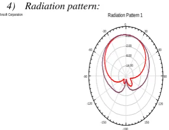
4) Radiation pattern:
-14.00 -8.00 -2.00 4.00
90 60 30 0 -30
-60
-90
-120
-150 -180
150 120
Ansoft Corporation Radiation Pattern 1 HFSSDesign1
Curve Info dB(GainTotal) Setup1 : Sw eep1 Phi='0deg'
dB(GainTotal) Setup1 : Sw eep1 Phi='90deg'
Fig.15: Radiation pattern of 2×2 E slot microstrip patch antenna array
[image:4.595.38.282.519.710.2]The simulation results indicate that 2×2 E slot antenna array has better performance in terms of return loss, VSWR, gain and directivity as compared to 2×2 U slot microstrip antenna array. Here, with the help of a comparison table, a comparison is made between the three arrays performance parameters such as return loss, VSWR, gain and radiated power.
TABLE 2: Comparison table Performance
Parameters
Rectangular patch
U slot E slot
Return loss(dB)
-19.5811 -33.1975 -36.082
VSWR 1.8297 0.3802 0.2727
Gain(dB) 1.6355 5.013 5.855
Radiated power(W)
0.0784 0.9185 0.9563
[image:4.595.310.567.551.655.2]III.COMPARISONGRAPHS:
1.0 1.5 2.0 2.5 3.0 3.5 4.0 4.5 5.0 -40
-35 -30 -25 -20 -15 -10 -5 0 5
R
et
ur
n l
os
s
(dB
)
Frequency (GHz)
Rectangular patch(without slot) U slot
E slot
Fig.16: Showing variation in the return loss values of the three antenna arrays
1.0 1.5 2.0 2.5 3.0 3.5 4.0 4.5 5.0
0 5 10 15 20 25 30 35 40 45
VSW
R
Frequency (GHz)
Rectangular patch(without slot) U slot
E slot
Fig.17: Showing variation in the VSWR of the three antenna arrays
-250 -200 -150 -100 -50 0 50 100 150 200 250 -25
-20 -15 -10 -5 0 5 10
G
ai
n(
dB
)
angle (deg)
Rectangular patch(without slot) U slot
E slot
Fig.18: Showing variation in the gain values of the three antenna arrays
-200 -150 -100 -50 0 50 100 150 200 250 300
0.00 0.07 0.14 0.21 0.28 0.35 0.42 0.49 0.56 0.63 0.70 0.77 0.84 0.91 0.98 1.05
R
ad
iat
ed pow
er
(W
)
Angle(deg)
Rectangular patch(without slot) U slot
E slot
Fig.19: Showing variation in the radiated power of the three antenna arrays
IV.CONCLUSION
In this paper, a comparative analysis of the three antenna arrays having the same size and design considerations, is presented. The simulation results indicates that the E slot antenna array has better results as compared to rectangular patch antenna array and U slot antenna array. E slot antenna array has return loss value -36.082dB at 2.41GHz, VSWR value is 0.2727 and gain is 5.855 dB.
V. REFERENCES
[1] M. Vasujadevi, Dr. P. Siddaiah and S Nagakishore Bhavanam "Rectangular Patch Antenna Array Design at 13GHz Frequency Using HFSS14.0". Springer India : Advancements of Medical Electronics, Chapter : 24, ISSN : 2195-2728, ISBN : 978-81-322-2255-2, ISBN : 978-81-
322-2256-9 (eBook), Springer Book Publications, January 2015, pp.263-270.
[2] Vasujadevi Midasala and Dr. P. Siddaiah, “Microstrip Patch Antenna Array Design To Improve Better Gains”, proc. International Conference on Computational Modeling and Security(CMS 2016), pp. 401-409.
[3] J. S. Herd and A. J. Fenn, “Design considerations for space-based radar phased arrays”, in Proc. IEEE MTT-S Int. Microw. MTT-Symp. Dig., Jun12-17, 2005, p. 4. [4]. T. Clark and E. Jaska, “Million element ISIS array,” in
Proc. IEEE Int. Symp. Phased Array Syst. Technol. (ARRAY),Oct.12-15,2010,pp.29-36.
[5]. Rajat Arora, Ajay Kumar, Saleem Khan and Sandeep Arya, “ Finite Element Modeling and Design of Rectangular Patch Antenna with Different Feeding Techniques”, Open Journal of Antennas and Propagation, vol.1, pp.11-17,2013.
[7]. M. Surita and A. Marwaha, “Finite Element Analysis for Optimizing Antenna for Microwave Coagulation
![Fig.2: Return loss of 2×2 rectangular microstrip antenna Freq [GHz]array](https://thumb-us.123doks.com/thumbv2/123dok_us/686429.1076035/2.595.36.284.379.602/fig-return-loss-rectangular-microstrip-antenna-freq-array.webp)