L. Boudin, C. Grandmont, Y. Maday, B. Maury, B. Sapoval & J.-F. Gerbeau, Editors
SPRAY IMPINGEMENT ON A WALL
IN THE CONTEXT OF THE UPPER AIRWAYS
∗Laurent Boudin
1,2and Lisl Weynans
1,3Abstract. We here address the modelling of an aerosol hitting the walls of the airways or an endotra-cheal tube used for a mechanical ventilation, and the possible creation of secondary droplets that may follow. We present a kinetic modelling of the spray-wall interaction and propose a boundary term that takes into account the possible formation of secondary droplets. Next we answer the following ques-tion: when, modelling the delivery of solute therapeutic aerosols, is it necessary to take into account the apparition of secondary droplets? A study of empirical models of drop-wall interaction allows us to conclude that in usual respiratory conditions, no secondary droplets appear. Finally, we perform numerical simulations of an aerosol delivered in an endotracheal tube, in the mechanical ventilation case. The idea is to compare our numerical results to in silico experiments from aerosols specialists. We study the trajectories and the deposition locations of spray droplets.
1.
Introduction
In this work, we address the modelling of the aerosol impingement on walls, in the context of human breathing. We are especially interested in the human upper airways, where the air behaviour is classically modelled by the incompressible Navier-Stokes equations, see for example [12]. Aerosols are used as medical treatment for many respiratory diseases. When they are liquid, which is the case we aim to study here, they are sent into the airways to the lungs by jet nebulizers. The aerosol can be delivered directly in the upper airways (trachea, larynx, pharynx), or through an endotracheal tube in case of mechanically ventilated patients. Part of the aerosol is lost by deposition on the wall. The treatment efficiency is obviously related to the amount of the aerosol which reaches the lung. To estimate which amount of the aerosol deposits on the endotracheal tube or the upper airways, and which amount actually reaches the respiratory tract, in vitro studies, such as [30], can be complemented by numerical simulations.
There are many ways to model an aerosol. If there are very few particles, one can treat each particle as a numerical individual and perform direct numerical simulations on it, as it is possible for particles in blood flows. Unfortunately, the medical aerosols are constituted of numerous particles, so that direct numerical simulations are too expensive. It then seems quite natural to use a kinetic model for the aerosols [3,11]. As a matter of fact, that kind of fluid, which is in the frame of rarefied gases, allows to consider particles from a statistical point of view.
∗ This work has been funded by the ACIlepoumonvousdisje (resp. B. Maury) and by the INRIA Paris-Rocquencourt project team REO (resp. J.-F. Gerbeau).
1 Univ. Pierre et Marie Curie, Lab. J.-L. Lions, 175 rue du Chevaleret, BC 187, F-75013 Paris, France;
e-mail:[email protected]
2 INRIA Paris-Rocquencourt, REO Project team, BP 105, F-78153 Le Chesnay Cedex, France
3Univ. Bordeaux 1, IMB, 351 cours de la Libration, F-33405 Talence Cedex, France; e-mail:[email protected]
c
As already stated, this work is more specifically dedicated to the study of a particle impingement on the wall of the human airways. Droplets impinging on a solid surface (dry wall or thin fluid film) usually deposit or splash. In the latter case, secondary droplets are ejected from the wall. The boundary between deposition and splashing has been widely investigated in the last years, both empirically and theoretically. It is generally described using a parameterK, function of the Ohnesorge and Weber numbers of the impinging droplet [5, 6, 23, 25, 29]:
K= We Oh−2/5, with We =̺DV02
σ , Oh = µ (̺σD)1/2,
where̺,σandµrespectively denote the density, surface tension and viscosity of the droplet,Dits diameter and V0 its velocity. IfK exceeds a threshold valueKs, then the splashing occurs. Sometimes, the Weber number
of the droplet is used as the splashing parameter instead ofK [16, 31]. For more details on the general droplet impingement phenomenon, we refer to the reviews of Rein [27] and Yarin [33].
Most models were built from observations made in the case of a one-droplet impingement, where the incoming velocity is normal to the wall [31,32]. However, some authors recently began to take into account the interactions between impinging droplets that exist in the case of a spray, as well as the effect of an inclined impingement. We prefered Kalantari and Tropea’s model [17], because it is, to our knowledge, the only one established from real spray impingement observations. In particular, it accounts for inclined impingements. Details about this model and two other ones [18, 24], quite comprehensive, are given in the appendix. Note that most existing models for secondary droplets are reviewed in [5].
Since the aerosol evolves in an ambient fluid (the air), there may be some interactions between them. A common assumption is that the aerosol has no effect on the air, in the context of the airways. Hence, the aerosol may be considered as a thin or a very thin spray. The difference between these two kinds of spray lies in the action of the aerosol on the air. We can assume, as in [11], that the aerosol is thin, i.e. it does globally act on the air. The numerical context of [11] mimics O’Rourke’s [26] and uses the Kiva-3V code [1]. Note that if we assumed that the aerosol was very thin, we would not eventually need a specific equation for the particles, for they would instantaneously get the air velocity. Hence we get a strongly coupled Vlasov-Navier-Stokes system, which is further detailed in Subsectn. 2.1.
Such coupled fluid-kinetic models have been studied a lot recently from an analytical point of view. For instance, Hamdache [13] tackled the existence problem for the Vlasov-Stokes system. Baranger and Desvillettes [4] proved the existence of classical solutions in small times for the Vlasov-Euler system. And more recently, Mellet and Vasseur [20] studied the existence of global weak solutions to the Vlasov-Fokker-Planck equations coupled with the Navier-Stokes equations. There have been lots of numerics dedicated works too: see [2,14,15,19] for instance. Our model is further discussed in the next two sections, then we address the effect of the impingement of a droplet on a wall, and eventually we present a numerical test in an endotracheal tube.
2.
Aerosol modelling
2.1.
Fluid-kinetic modelling
velocityuand the pressurep, which depend ont andx:
∂tu+∇x·(u⊗u) +∇xp = 0, (1)
∇x·u = 0, (2)
∂tf+∇x·(vf) +∇v·(af) = 0, (3)
whereais the droplet acceleration, mainly due here to the Stokes force exerted on the aerosol by the fluid, and is given by
a(t, x, v, r) =−6πµr(v−u(t, x)). (4) Note that the initial radius distribution of the aerosol is obviously conserved since there is no action on the variable r in (3). The dependence of f on r allows to send particles with various radii in the computational domain.
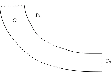
The boundary conditions (see Fig. 1) for the Navier-Stokes equations are the following:
u(t, x) = u1(t) ifx∈Γ1, (5)
u(t, x) = 0 ifx∈Γ2, (6)
whereu1 is the profile of the incoming velocity in Ω. Note that there is no condition on Γ3.
Γ1
Γ2
Γ3
Ω
Figure 1. Domain and boundaries.
2.2.
Boundary conditions for the aerosol
To take into account the possible impingement of droplets on walls, one must add an adequate boundary condition to Eqn. (3) above. Actually, in order to describe the evolution off, it is necessary to know if secondary droplets are created on the walls, and if there are, what their locations, velocities and radii are. Hence, we only need to prescribe, as a boundary condition, the value off for velocities emerging from the wall.
Define in every pointxof the wall the normal vector to the walln(x). We consider that the droplet located in x, with velocityv and radiusrdoes hit the wall ifxis really on the wall, and if velocityv satisfiesv·n(x)<0, which means that the droplet is heading to the wall.
We propose the following boundary condition, forx∈Γ2 andv·n(x)<0,
f(t, x, v, r) =
Z
r∗∈R+
Z
v∗∈R2
χ[v∗.n(x)<0](x, v ∗
)Nsec(K, v
∗ , v, r∗
, r)f(t, x, v∗ , r∗
) dv∗
In the previous equation, Nsec(K, v
∗, v, r∗, r) represents the number of secondary droplets of velocity v and
radius r, appearing because of the impingement of droplets of radius between r∗ andr∗+ dr∗ with velocity
betweenv∗ andv∗+dv∗. It depends onK: ifK does not exceed a threshold valueK
s, then the droplet simply
deposits on the wall, and no secondary droplet is created, so thatNsec(K, v∗, v, r∗, r) = 0. It can be a Gaussian
distribution, as in [24] and [16], or a punctual distribution, as in [18]. Note that kinetic equations with similar boundary conditions have been studied from the mathematical point of view by Mischler [21, 22].
2.3.
Splashing or deposition?
Here we want to discuss if the drop splashing in the endotracheal tube can occur during a mechanical ventilation. Note that a droplet splashing cannot occur on the upper airway walls, because these walls are covered of viscous mucus that absorbs and retains every droplet reaching its surface. Thus discussing splashing or deposition is only relevant in the endotracheal tube.
According to [17], the critical Weber number for splashing for a droplet impinging on a wall is approximately above 80. We here suppose that the aerosol solution properties are similar to water properties. Consequently, its viscosityµ, surface tensionσand density̺are:
µ= 9.78 10−4Pa.s, σ= 7.28 10−4 N.cm−1, ̺= 1.0 kg.m−3
.
Experiments with the endotracheal tube performed by aerosol specialists [9,30] deal with velocities between 0.25 and 1 m.s−1. With such velocities, the Weber number of spray droplets in the airways does not exceed the value
0.15. We conclude that splashing cannot occur in the endotracheal tube under usual ventilation conditions. Consequently, in the sequel, we shall not address either any more the possibility of splashing when considering the endotracheal tube. The boundary condition onf then simply becomes
f(t, x, v, r) = 0, ifx∈Γ2, v·n(x)<0. (7)
3.
Numerics
3.1.
Numerical solving
We use a standardP1−P2 finite element computation for the air flow, a particle method for the aerosol, to
solve (1)–(7). We do not give any detail on the fluid computation, since (1)–(2), (5)–(6) are solved thanks to the Navier-Stokes routine of the Freefem++ software [10]. Note that our numerical code is inspired from an
engineering project performed under B. Maury’s supervision [7].
3.1.1. Particle method
The equation describing the evolution of the PDFf involves a phase space of high dimension. Thus, using finite volume or finite difference methods to solve this equation, or simply performing direct numerical simulations on the droplets, would be too expensive. Particle methods appear to be an adequate compromise between the previous solutions. The same choice has been made in a previous attempt to model therapeutic sprays in [3]. Let us fastly present the particle method we here use. Since there are numerous droplets described from a statistical point of view, one must distinguish the physical droplets from the numerical particles. Let NP the
total number of numerical particles,NP is almost always much smaller than the number of droplets ND. The
PDF f is discretized in the following way:
f(t, x, v, r) =
NP X
p=1
ωp(t)δxp(t)(x)δvp(t)(v)δrp(t)(r),
where t 7→ (xp(t), vp(t), rp(t)) is the trajectory of the numerical particle p in the phase space, and ωp(t) its
Figure 2. Experimental device with the endotracheal tube (T. Duparque, Inserm Tours).
characteristics and coordinates are very close to the ones ofp. Note that the average value ofωpis approximately
of the orderND/NP.
3.1.2. Impingement resolution
A crucial aspect of the numerical solving is the detection of impingements. In order to ascertain if a droplet actually reaches the wall or not, we need to evaluate accurately the distance between this droplet and the wall. In [7], a method to estimate this distance is proposed, which consists in numerically solving the following problem in the computational domain:
−∆θ= 1 in Ω, θ= 0 on∂Ω. (8)
For small values of θ, isovalues of θ approximate the distance to the walls, and the function Θ = θ/||∇θ||
represents a good approximation of this distance. In our numerical code, Equation (8) is solved. If the value of Θ computed at the location of a particle is smaller than a numerical threshold, then we consider that this particle has hit the wall. More details about this way of estimating the distance can be found in [28].
3.2.
Numerical test
Here we want to numerically predict the trajectories and deposition locations of aerosol droplets in the endo-tracheal tube used for the mechanical ventilation (Fig. 2). We aim to compare our numerical results with the results obtained with in vitro experiments by aerosols specialists [9]. The simulations are performed with the scientific computation softwareFreefem++[10]. Numerical results are plotted with an enhanced version of the
visualization softwaremedit[8]. Note that the radius of the particles are not taken into account in Fig. 3 and 4,
Figure 3. Particle locations after the first ejection.
flow, each computational time step for the fluid solving is divided into 50 time sub-steps to solve the particle motion.
The computational domain reproduces in 2D the exact measures of the endotracheal tube used for the mechanical ventilation in the experimental tests. The endotracheal tube is shaped like the upper airways of a lying down patient (see Fig. 2). It is curved, and can be contained in a box of height 25.5 cm and length 21.6 cm. The computational parameters reproduce an experiment performed by aerosol specialists [9]. In particular, several identical ejections happen in a row, in order to mimic the continuous aerosol diffusion of the experiment. More precisely, 20 ejections of 50 particles happen, separated from each other by 6 time steps. All particles have a radius of 1.85 µm. The rate of flow at the entrance of the tube is 34 l/min, which corresponds to an average incoming velocity of 2 m.s−1, and is stationary, because the experiments involved a stationary flow in the tube.
All the physical quantities used for the test were given by our fellow experimenters from Inserm Tours, and detailed in [9].
Fig. 3 shows particle locations after the first ejection and Fig. 4 after several ejections (respectively after 3 and 12 ejections). The qualitative results are quite satisfying: there is approximately 80 % of the inhaled aerosol which reaches the tube output in both the experimental and numerical situations.
A.
Appendix: Splashing models
In this appendix, we present a selection of splashing models established from experimental results. As the splashing phenomenon occurs in three dimensions, several parameters need to be known in order to correctly describe the creation of secondary droplets, as the number of secondary droplets, their sizes and velocities. In the following, the indexb denotes the values before impingement, andathe values after impingement.
A.1.
Marengo and Tropea [18]
The authors performed an experimental analysis of the secondary droplet characteristics, but only with water. The model can be used for a quasi-normal impingement angle: α > 80◦, with αdenoting the angle between
the wall and the direction of the velocity of the impinging droplet, for Kr = K/1000 <4, and for δ =h/D
the adimensionalized thickness of the liquid film between 0.5 et 2, withhthe liquid film thickness and D the impinging droplet diameter. The parametersua/ub,va/vb, d10/D andd32/D, describing the size and velocity
of secondary droplets, are expressed by the general formula:
(A1+A2δ) + (A3+A4δ)(Kr−K0).
withKr=K/1000 etK0=Ks/1000 and the values ofA1,A2,A3 andA4 given in the following table.
A1 A2 A3 A4
ua/ub 0.056 0.057 0.038 0.00
va/vb 0.311 −0.077 −0.009 −0.024
d10/D mean diameter 0.209 0.100 −0.096 0.005
d32/Dmean Sauter diameter 0.250 0.238 −0.022 −0.128
The numberd10denotes the arithmetical mean diameter of the secondary droplets, andd32represents the mean
Sauter diameter of the droplets, i.e. the diameter of a droplet having the same volume/surface area ratio as the whole set of secondary droplets.
The relationship between the deposited mass, concentration and number of secondary droplets and the impinging (or primary) quantities are the following:
msec/mprim = (B1+B2δ)(Kr−K0)(B3+B4δ),
Nsec/Nprim = (B1+B2δ)(Kr−K0)(B3+B4δ),
Csec = max
0,1 +B1+
B1(Kr−K0)
1−eKr−K0 2
(B2+B3δ)(Kr−K0)
where the values ofB1,B2,B3 andB4 are given in the table below.
B1 B2 B3 B4
msec/mprim 0.363 0.242 2.928 −1.521
Csec 60.8 0.685 0.036 n/a
Nsec/Nprim 0.285 0.073 0.630 −0.100
A.2.
Mundo, Sommerfeld and Tropea [24]
This model was established from experimental results reported in [23, 24] in the case of a liquid film of adimen-sionalized thicknessδ=h/D= 0.03. The velocities of secondary droplets obey a Gaussian distribution around average values depending on the size of the impinging droplet and the velocity before impingement. Splashing occurs whenKexceeds the value 57.7. The deposited mass fraction, the diameter and the number of secondary droplets obey the following laws:
Diameterda = min 8.72 exp(−0.0281K),1db,
Number of sec. dropletsna = 1.676×10⁻⁵K2.539nb
Deposited mass fraction mdep
m = max 1− na
nb
d
a
db
3
,0
!
.
A.3.
Kalantari and Tropea [17]
This model holds for a negligible surface roughness, with the entire target surface exposed to the impinging spray. The accumulated wall film thickness must stand in the range 8 µm ≤¯h≤ 107µm, the impingement Weber number (based on the normal component of velocity before the impact) in the range 10≤Wen ≤160,
and the fluid viscosity must be low (Oh≪0.1). The Weber numbers Wen and Wetare respectively computed
with the normal and the tangential components of the impinging velocity.
Parameter General correlation Normal component of velocity (m/s) ua/ub=−1.1We0n.36
Tangential component of velocity (m/s) va = 0.862vb+ 0.094
Droplet trajectory angle (deg) θa= 0.623θb+ 41
Mean droplet size (µm) da/db =−0.003Wen+ 1.2
Mass ratio (normal impact, Wet/Wen <0.1) ma/mb= 0.00674Wen−0.204
Mass ratio (oblique impact, Wet/Wen≥0.1) ma/mb= 35We−n1.63
Number ratio (normal impact, Wet/Wen<0.1) Na/Nb= 0.0022Wen+ 0.0896
Number ratio (oblique impact, Wet/Wen≥0.1) Na/Nb= 7.1We−n1.14
Acknowledgement. The authors would like to thank Marcela Szopos for her big contribution and Vincent Ducrot for his help, both on the post processing part of this work during Cemracs ’07, and C´eline Grandmont for the discussions we shared on the topic.
References
[1] A. A. Amsden. Kiva-3V: A block-structured Kiva program for engines with vertical or canted valves. Technical report, Los Alamos National Laboratory Report LA-13313-MS, Los Alamos, NM, 1997.
[2] C. Baranger. Modelling of oscillations, breakup and collisions for droplets: the establishment of kernels for the T.A.B. model. Math. Models Methods Appl. Sci., 14(5):775–794, 2004.
[4] C. Baranger and L. Desvillettes. Coupling Euler and Vlasov equations in the context of sprays: the local-in-time, classical solutions.J. Hyperbolic Differ. Equ., 3(1):1–26, 2006.
[5] G. E. Cossali, G. Brunello, A. Coghe, and M. Marengo. Impact of a single drop on a liquid film: experimental analysis and comparison with empirical models. Italian Congress of Thermofluid Dynamics UIT, Ferrara, 30 june - 2 July 1999.
[6] G. E. Cossali, A. Coghe, and M. Marengo. The impact of a single drop on a wetted solid surface.Exp. Fluids, 22:463–472, 1997.
[7] Q. D´erumeaux and J. Crest. Mod´elisation du d´epˆot de particules dans les bronches. Technical report, ´Ecole Polytechnique, 2007.
[8] C. Dobrzynski and P. Frey. Medit, scientific visualization software,http://www.ann.jussieu.fr/ frey/logiciels/medit.html. [9] T. Duparque. Master report, universit´e de Tours, 2007.
[10] A. Le Hyaric F. Hecht, O. Pironneau and K. Ohtsuka. Freefem++, finite elements software,http://www.freefem.org/ff++/. [11] T. Gemci, T. E. Corcoran, and N. Chigier. A numerical and experimental study of spray dynamics in a simple throat model.
Aerosol Sci. Technol., 36:18–38, 2002.
[12] C. Grandmont, Y. Maday, and B. Maury. A multiscale/multimodel approach of the respiration tree. InNew trends in continuum mechanics, volume 3 ofTheta Ser. Adv. Math., pages 147–157. Theta, Bucharest, 2005.
[13] K. Hamdache. Global existence and large time behaviour of solutions for the Vlasov-Stokes equations.Japan J. Indust. Appl. Math., 15(1):51–74, 1998.
[14] J. Hylkema and P. Villedieu. A random particle method to simulate coalescence phenomena in dense liquid sprays. InProc. 16th Int. Conf. on Num. Meth. in Fluid Dyn., volume 515 ofLecture Notes in Physics. Springer-Verlag, 1999, 1999. [15] J. Hylkema and Ph. Villedieu. Mod´elisation cin´etique et simulation num´erique des collisions entre gouttelettes d’alumine dans
un propulseur `a poudre. In Y. Fabignon et P. Marion, editor,Actes du 3`eme colloque R&T sur les Ecoulements Internes en Propulsion Solide, Poitiers, Mars 1998, volume 2, pages 119–139, 1998.
[16] D. Kalantari and C. Tropea. Comparison between splash of a droplet in isolation and in a spray. Spray Workshop 2006, May 29-30th, Lampoldshausen, Germany, 2006.
[17] D. Kalantari and C. Tropea. Spray impact onto flat and rigid walls: empirical characterization and modelling.Int. J. Multiphase Flow, 33:525–544, 2007.
[18] M. Marengo and C. Tropea. Aufprall von Tropfen auf Flussigkeitsfilme. Tr. 194/10, 1,2, Deutsche Forschungsgemeinschaft, 1999.
[19] J. Mathiaud.Etude de syst`´ emes de type gaz-particules. PhD thesis, ´Ecole Normale Sup´erieure de Cachan, 2006.
[20] A. Mellet and A. Vasseur. Existence and uniqueness of global strong solutions for one-dimensional compressible Navier-Stokes equations.To appear in SIAM J. Math. Anal., 2007.
[21] S. Mischler. On the initial boundary value problem for the Vlasov-Poisson-Boltzmann system.Comm. Math. Phys., 210(2):447– 466, 2000.
[22] S. Mischler. On the trace problem for solutions of the Vlasov equation.Comm. Partial Differential Equations, 25(7-8):1415– 1443, 2000.
[23] C. Mundo, M. Sommerfeld, and C. Tropea. Droplet-wall collisions: experimental studies of the deformation and breakup process.Int. J. Multiphase Flow, 21 (2):151–173, 1995.
[24] C. Mundo, M. Sommerfeld, and C. Tropea. Experimental studies of the deposition and splashing of small liquid droplets impinging on a flat surface. Proc. ILASS-95, Nuremberg, Germany, 1995.
[25] C. Mundo, M. Sommerfeld, and C. Tropea. On the modeling of liquid sprays impinging on surfaces.Atomization and Sprays, 8:625–652, 1998.
[26] P. J. O’Rourke. Statistical properties and numerical implementation of a model for droplet dispersion in a turbulent gas.J. Comput. Phys., 83:345–360, 1989.
[27] M. Rein. Phenomena of liquid drop impact on solid and liquid surfaces.Fluid Dynamics Research, 12:61–93, 1993. [28] G. Strang. Level sets and the fast marching method, Applied Mathematics and Scientific Computing, 2007.
[29] C. Tropea and I. Roisman. Spray-wall interaction: How much physics do we need in our models? 6th World Conference on Experimental Heat Transfer, Fluid Mechanics and Thermodynamics, April 17-21, Matsushima, Miyagi, Japan, 2005. [30] L. Vecellio, C. Gu´erin, D. Grimbert, M. De Monte, and P. Diot. In vitro study and semiempirical model for aerosol delivery
control during mechanical ventilation.Intensive Care Med, 31:871–876, 2005.
[31] R. L. Vander Wal, G. M. Bergerand, and S. D. Mozes. The splash/non splash boundary upon a dry surface and thin fluid film. Exp. Fluids, 40:53–59, 2006.
[32] A. L. Yarin and D. A. Weiss. Impact of drops on solid surfaces: self-similar capillary waves, and splashing as a new type of kinematic discontinuity.J. Fluid Mech., 283:141–173, 1995.