Division VI Paper ID: 06-15-05
ON THE PERFORMANCE OF STEEL-CONCRETE COMPOSITE (SC)
MODULAR STRUCTURES FOR SEISMIC AND ACCIDENT THERMAL
CONDITIONS
Kadir Sener1, Amit H. Varma2 and Meng Chu3
1 Research Engineer, Civil Engineering, Purdue University, West Lafayette, IN, USA
2 Professor, Civil Engineering, Purdue University, West Lafayette, IN, USA
3 Senior Engineer, Shanghai Nuclear Engineering Research and Design Institute, Shanghai, China
ABSTRACT
This paper presents a numerical study to estimate the lateral load performance of steel plate-concrete (SC) modular structures subjected to accident thermal loading. Finite element analysis (FEA) method was employed to perform the structural pushover analysis of an idealized steel-concrete (SC) modular structure. The paper will elaborate the findings from the study including the nonlinear behaviour of the SC modular structures under seismic and accidental thermal loading incorporating different modeling techniques. The results from nonlinear analysis are used to develop a of linear elastic analysis approach for design. The linear elastic analysis approach is demonstrated to be an efficient tool for establishing the response and calculating SC modular subjected to seismic plus operating and accident thermal conditions.
INTRODUCTION
Steel plate-concrete (SC) modular structures are widely used in the internal safety shell of pressurized water reactor (PWR) structures. In the design of large modular structures, the extreme loading scenarios should be considered, for example, seismic loading, operational or accident thermal loading, compressive forces, and the combinations of these loading scenarios. The seismic + accident thermal loading is usually the controlling load combination, under which the system strength may be reached due to thermal effects.
The main objectives of this study are to (i) evaluate the nonlinear seismic response of large steel plate-concrete (SC) modular structure, (ii) estimate the lateral load performance under concurrent accident thermal loading, (iii) develop linear analysis method using the results from nonlinear analysis, and use this method to estimate the response of the entire SC modular structure.
LITERATURE REVIEW AND BENCHMARK MODELING
Experimental and numerical investigations on the behavior of SC walls that are subjected to mechanical and accident thermal loading conditions have been carried out by several researchers. The following is a summary of the findings from select publications available in literature which forms the basis for the current study. Some of the tested specimens presented in this section were used to benchmark the finite element models that were used for the analysis of an idealized SC modular structure.
Seismic behavior of a containment internal structure consisting of composite SC walls
finite element model accounted for geometric and material nonlinearities including yielding and local buckling of the steel plates, and tensile cracking and compression plasticity of the concrete. The analysis results with experimental observations were used to explain the overall lateral load-deformation behavior of the CIS including the formation of ductile energy dissipating mechanisms in the SC walls. The authors recommended the 3D shell-solid models for evaluating the seismic (lateral load) behavior and design of similar CIS consisting of SC walls, where failure occurs in the SC walls. The simplified layered composite shell (LCS) model was recommended for evaluating the lateral stiffness and predicting the lateral load capacity of the CIS consisting of SC walls. The LCS elements have three layers (steel– concrete–steel), and each layer has several integration points through the thickness to account for speecific material behavior. The LCS model does not account for slip between the layers; therefore, the interaction between the steel and concrete portions are similar to a 3D shell-solid tie model.
Seismic behavior and design of a primary shield structure consisting of (SC) walls
A numerical evaluation of the seismic behavior of a previously tested primary shield (PSW) structure consisting of steel-plate composite (SC) walls was also performed by the authors (Booth et al. 2015). The test conducted by researchers in Japan was a reduced (1/6th) scale PSW structure tested to evaluate its seismic (lateral) load-deformation behavior. Booth et al., 2015 presented the development and benchmarking of a detailed 3D nonlinear inelastic finite element model to predict the lateral load-deformation response and behavior of the test structure. The results from the 3D shell-solid analyses included the lateral load-deformation behaviour of the PSW structure, the progression of yielding in the steel plates, concrete cracking, formation of compression struts, and the final failure mode. A simplified 3D linear elastic finite element model of the PSW structure was also proposed as a conventional structural analysis tool for estimating the design force demands for various load combinations.
SC Flanged Wall Tests with Thermal Loading
Japanese researchers have carried out experimental and numerical studies on the seismic behavior of SC walls subjected to accident thermal loading (Kitajima et al. 2015). The researchers conducted tests of SC wall specimens that failed in in-plane shear mode. The tested specimens were 1/7 scale SC walls. The specimens had a wall thickness of 285 mm (11.2 in.), steel faceplate thickness of 2.3 mm (0.09 in.), and end (flange) plate thickness of 22 mm (0.87 in.). The test results showed that the lateral load capacities of the specimens were reduced by 25% due to the thermal loading. Additionally, significant reduction (about 50%) in the pre-yielding stiffness response was observed due to the thermal loading.
The monotonically loaded specimen tested under ambient condition (Specimen No. 2) was modeled using 3D shell-solid finite element method for benchmarking FE models. The model used solid elements for the concrete infill, shell elements for the steel faceplates, and a combination of beam and connector elements to model the shear studs and their interfacial shear behavior. The lateral shear force-deformation response of Specimen No. 2 is compared with the numerical analysis results in Figure 1. The comparison indicates that the experimentally measured stiffness and strength is predicted accurately by the analysis results. The figure also includes the load-displacement comparison obtained from two models that do not model shear studs and instead full bond is defined between steel and concrete surfaces, referred as the tie models. The first tie model is built using solid elements for concrete and shell elements for faceplates. The second tie model was built using the LCS elements for the SC wall. As seen in the comparison figure, almost identical initial stiffness and ultimate strengths were observed from the analysis results of all three models. The two tie-models over-estimated the post-concrete cracking stiffness in the load-displacement response as slip between the concrete infill and faceplates was not accounted for.
induced tension stresses in the concrete infill through the interfacial bond. The tension stress in concrete caused cracking and element removal in the 3D shell-solid model. The removal of several solid elements significantly diminished the in-plane shear resistance of the walls. Thus, the shear loading phase of the analysis using the 3D shell-solid model could not be completed due to extensive concrete element removal that occurred in the heating phase of the specimen. Therefore, the lateral load behavior of Specimen No.5 was predicted using the LCS model of the SC wall specimens. The comparison shown in Figure 1 indicates that the initial stiffness and ultimate strength was captured accurately by the LCS model results. The response in the post-concrete cracking region had several discrepancies because the LCS model due to not accounting for slip between layers. The difference between the tie model and connector model in the post-cracking region is expected to diminish with models of SC walls using interface elements, such as shear studs, more densely.
Figure 1 - Load-Deformation Comparison of Specimens No. 2 and No. 5 from Kitajima et al. (2015)
SC Panel Tests with Combined Mechanical-Thermal Loading
The LCS models used in the study of the idealized structure were also benchmarked using the results from SC wall panel experiments conducted in Japan by Ozaki et al. (2004). The experiments included shear panel tests at ambient and elevated temperature conditions. The benchmarking analysis discusses two unheated specimens (S200NN, and S400NN), and the two corresponding heated specimens (S200TH and S400TH). All the test specimens had the same overall dimensions of 1200 mm x 1200 mm
x 200 mm (47.244 in.x 47.244 in. x 7.874 in.), with only differences in the faceplate thickness (tp). The
faceplate thicknesses were; 2.3 mm, 4.5 mm (0.09 in, 0.169 in) for S200 and S400 series specimens, respectively.
Figure 2 includes the comparisons of the initial portions of the shear force-shear strain responses obtained from the tests of Specimen S200NN-S200TH and Specimens S400NN-S400TH with those predicted analytically using the LCS finite element models. The figure also includes conventional shell element models using the equivalent elastic properties calculated based on the equivalent shell properties calculated for uncracked and cracked SC walls based on the equations provided in AISC N690-12-s1. The comparisons between the analytically computed curves indicate that the heated specimens had lower initial stiffness due to cracking of concrete in the heating phase prior to the mechanical loading. It is illustrated in Figure 2 that the initial stiffness of the unheated specimens (S200NN and S400NN) follows the uncracked stiffness until the concrete cracking. The shear stiffness following the concrete cracking is
then reduced to cracked shear stiffness (GAcr). The initial stiffness of the pre-heated specimens (S200TH
difference between the heated and ambient cases were negligible because the strength was governed by the yielding of the faceplates. The benchmarking analysis results for shear panel tests indicate that the LCS finite element model can be used to predict the in-plane shear behavior of SC shear walls with reasonable accuracy and conservatism.
Figure 2 – Initial shear stiffness responses of S200NN-S200TH and S400NN-S400TH
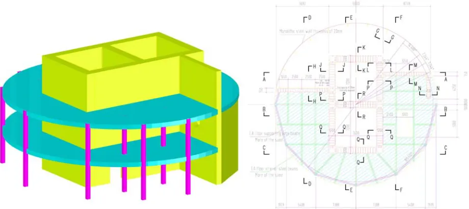
IDEALIZED SC MODULAR STRUCTURE GEOMETRY
An idealized large steel-plate concrete (SC) modular structure geometry was developed for conducting the investigation. This idealized structure modeled a generic containment internal structure including the steam generator and pressurizer compartments, and reactor cavity walls, all made of SC composite walls. The isometric and plan views of the idealized structure are illustrated in Figure 3. The walls located in the core of the structure were 1200 mm thick, and the side (wing) walls were 750 mm. The steel faceplates were 14 mm thick with yield strength equal to 345 MPa. The faceplates were anchored to the concrete infill using 19 mm diameter studs spaced at 150 mm. Shear reinforcement was provided with 20 mm diameter round deformed bars spaced at 450 mm from steel with 400 MPa yield strength. The compressive strength of concrete was taken equal to 28 MPa.
MODELING APPROACH
The models were developed according to the benchmarking studies that were based on the experimental results and observations of previous test programs. In order to accomplish the objective tasks, three different finite element models were developed to analyze the structure under different loading conditions. The first task of evaluating the lateral load behavior of the idealized SC modular structure by performing pushover analysis was accomplished using the 3D shell-solid connector and tied models. This modeling approach was demonstrated for estimating the lateral load behavior and response of Specimen No. 2 of the Japanese test program, and was also implemented in the models evaluating the
performance of the 1/10th scale structure (Sener et al., 2015) and primary containment structure (Booth et
al., 2015). The second task of estimating the lateral load performance while subjected to accident thermal loading was accomplished using the LCS modeling approach, which was presented for Specimen No. 5 previously.
The results from the shell-solid connector and tie, and LCS models were compared to ensure that the response and behavior at ambient condition was modelled reasonably by all these approaches. The faceplate slenderness ratio of the idealized SC modular structure model was smaller than that of the
specimens tested by the Japanese researchers (s/tp = 10.7 vs. 20); therefore, less discrepancy between the
tied models and connector models were expected. The third task of developing linear analysis methods for estimating the response of the overall structure under operating and accident thermal loading conditions was accomplished by using conventional shell elements with calculated equivalent section properties.
Constitutive Material Properties Used in Models
The element libraries available in Abaqus were used to model the steel faceplates, concrete infill, stud anchors, tie bars and the contact interaction between steel and concrete. Additionally, the material libraries available in Abaqus were used to model the nonlinear behavior of steel and concrete materials. The explicit dynamic analysis approach was used to perform the quasi-static analyses because of extensive concrete cracking and slip at the interface.
Concrete infill in the 3D shell-solid models were created using eight node solid elements with reduced integration (C3D8R) elements with 150 mm in size. The concrete material model used for the analysis was the brittle concrete cracking or concrete elastic fracture (CEF) model. The CEF model uses multi-directional anisotropic smeared cracking behavior in tension. This material model also allows for element removal after it has completely exhausted its resistance. The post-peak behavior after cracking is defined using the bilinear softening curve for plain concrete provided in the fib Model Code (2010).
The steel faceplates were modeled using shell elements because of their geometry (thickness much less than length or width). The faceplates were modeled using 4-node shell elements with reduced integration (S4R). This S4R element is a linear, finite-membrane-strain, quadrilateral shell element that is suitable for both thick and thin plate type problems. The steel material is modeled using multiaxial plasticity theory with von-Mises yield surface. The contact between steel faceplates and concrete infill was modeled as ‘Hard contact’ in the normal direction and ‘Frictionless’ in the tangential direction.
The shear studs and tie bars were modeled using a combination of beam and connector elements. The connector elements were used to model the interfacial behavior between the steel faceplate and concrete infill. This simplified approach was developed and verified for SC walls by Zhang et al. (2014) using both experimental and numerical studies. The connector element was defined between coinciding nodes of the beam element and the faceplate shell element at the locations of stud anchors. The beam elements (B31) were used to model the shank regions, and connector elements were used to model the interfacial behavior between the steel faceplate and concrete infill. The beam elements were embedded into the concrete infill and constrained to the surrounding concrete elements.
the composite SC walls in the idealized modular structure. The thermal material properties (conductivity and specific heat) used in the heat transfer analyses were obtained from Hong and Varma (2009).
PUSHOVER ANALYSIS OF IDEALIZED SC MODULAR STRUCTURE
Three models, namely, the 3D shell-solid connector, the 3D shell-solid tied and the 3D LCS models were used to perform the pushover analyses. The 3D shell-solid models were almost identical with the exception that tie model had no tie bars and interfacial slip. The connector model accounted for the interfacial bond and slip between the steel faceplates and the concrete infill using connector models for the shear stud and tie bar contributions. The third model was built using LCS elements which utilize layers or plies to model the steel faceplates and the concrete infill sandwiched in between them.
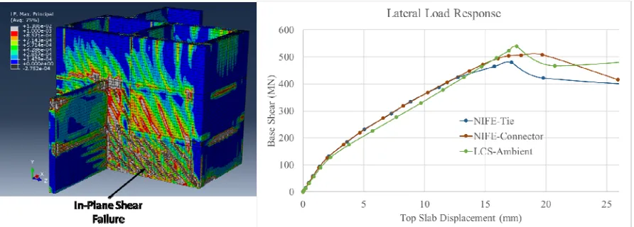
The pushover analysis was conducted by subjecting the structure to uniform lateral acceleration along the height of the structure. The boundary conditions were applied to the base of the SC structure in all three fundamental directions. Figure 4a shows the contour plots of concrete cracking from the 3D shell-solid connector model indicating significant cracking due to in-plane shear. Figure 4b compares the results from the three different models. As shown in Figure 4b, the base shear vs. top slab displacement responses from the monotonic analyses of the shell-solid connector and tie model were almost identical. The LCS model also predicted the response to be similar to those from the 3D shell-solid models up to the peak load. The base shear strength of the idealized structure was about 500 MN, with the LCS model reaching a slightly higher peak load.
Figure 4 –Load–Displacement Responses of 3D Shell-solid and LCS Analyses Results
The slight difference in the stiffness responses between the 3D shell-solid and LCS models is due to the shell approximation and not modeling the inner plates at the wall corners in the LCS model. The strength differences between the shell-solid and LCS models are due to the concrete element failure/removal that only the 3D shell-solid models are capable of capturing. The finite elements in the LCS model represent both faceplate and concrete layers in the same element without the element failure/removal feature, which causes the LCS model to predict a slightly larger lateral load capacity for the idealized SC structure.
Table 1 - Comparisons of Analysis Results of 3D Shell-solid and LCS Models
Ratio (/Shell-Solid Connector)
Model
Initial Stiffness (MN/mm)
Cracked Stiffness (MN/mm)
Lateral Strength
(MN)
Initial Stiffness
Cracked
Stiffness Strength
3D Shell-solid Connector 66.1 27.3 508 100% 100% 100%
3D Shell-solid Tie 65.5 28.6 480 99% 105% 95%
LCS 61.3 26.0 539 93% 95% 106%
The two-3D shell-solid and the LCS analysis results indicated that the seismic (lateral load) behavior including the stiffness, strength, and drift capacity of the idealized SC structure is governed by the in-plane shear behavior (and corresponding yielding of the steel faceplates) of the SC walls located in the center of the structure. The lateral load capacity of the CIS was also governed by the in-plane shear strength and failure of the SC walls parallel to the loading direction. The overturning moment at the base also contributed to inelastic deformations with extensive cracking and yielding in the SC walls at the exterior (outer) regions of the idealized SC structure. These findings are similar to those reported by Sener et al. (2015) based on experiments and analysis.
ACCIDENT THERMAL ANALYSIS OF IDEALIZED SC MODULAR STRUCTURE
The benchmarked LCS models were used to conduct studies on the idealized SC modular structures subjected to accident thermal loading conditions. The thermal loading was applied to the steel surfaces (both interior and exterior) of SC walls. The room (ambient) temperature was set equal to
T0=20°C and the study included three temperature amplitudes of T=100°C, T=150°C and T=232°C. The
loading protocol in the analytical models included three steps: (i) a mechanical load was applied that was sufficient to initiate cracking in concrete, (ii) the nodal temperatures for the particular surface temperature condition were applied to the structure and (iii) the mechanical load was gradually increased to the final force capacity of the structure as the temperatures in the model were maintained.
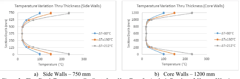
a) Side Walls – 750 mm b) Core Walls – 1200 mm
Figure 5 – Thru-Depth Temperature Gradients from Heat Transfer Analysis Results at 3 Hours of Heating
cross section with a steep variation from the target temperature on the surfaces to ambient temperature at the mid-height of the section.
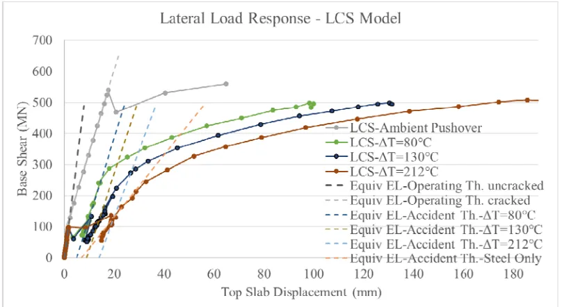
Figure 6 compares the base shear vs. top slab displacement response results from the monotonic analyses results of the LCS models for different temperature amplitude cases. The load-displacement response in the initial loading stage was identical for each analysis case prior to the heating stage. In step 2, subjecting the structure to thermal loading while maintaining the lateral force caused additional cracking in the concrete layers which resulted in displacement jumps in the lateral load response. The figure indicates that in the heating stage (step 2), the displacement jump increased for larger surface temperature amplitudes. The plots indicate reductions in the lateral stiffness after the heating stage due to extensive cracking in concrete infill and yielding in the steel faceplates. The occurrence of yielding at early stages of the loading resulted in non-linear curves for the model responses with thermal loading.
Figure 5 – Load-Displacement Responses of Thermally Loaded LCS Models
Table 2 - Comparisons of Results from Analysis at Ambient and Elevated Temperature Ratio (/Ambient)
Model Stiffness (MN/mm)Lateral Tangent Lateral Tangent Strength (MN) Stiffness Strength
LCS Ambient 26.0 post-cracking (61.3 initial uncracked) 558 100% 100%
LCS 100°C 23.1 500 89% 90%
LCS 150°C 13.2 496 51% 89%
LCS 232°C 10.2 508 39 % 91%
Ratio (/LCS)
LEFE – Op. Th. - uncracked 61.2 - 100% -
LEFE – Op. Th. - cracked 26.3 - 101% -
LEFE 100°C 25.8 - 112% -
LEFE 150°C 24.6 - 186% -
LEFE 232°C 21.5 - 211 % -
In spite of the changes in the characteristics of the load-displacement curves as shown in Figure 5, the models subjected to different temperature changes (ΔT=80-212°C), reached similar peak strength as predicted by the finite element models. Table 2 compares the tangent stiffnesses of the lateral response in the 100 MN to 200 MN base shear force range. The LEFE stiffnesses at ambient and elevated temperatures were compared with the stiffness obtained from the companion LCS results with same thermal condition, e.g. the ratio is given for LEFE 100ºC/LCS 100ºC (25.8 MN/mm / 23.1 MN/mm). As seen in the table, the lateral stiffness after the heating stage is reduced due to the thermally induced concrete cracking and the reduction in mechanical properties at elevated temperature. The lateral stiffness is largely reduced with higher surface temperature amplitude cases. The stiffness reduces to 89-39% for ΔT of 80-212°C, but the strength remains at 90% for the heated models.
ELASTIC SHELL MODELS: OPERATING & ACC. THERMAL LATERAL LOAD RESPONSE
Linear elastic finite element (LEFE) models were developed for performing analysis using equivalent conventional shell elements. These models evaluated the lateral load response at operational and accident thermal conditions. Cracked equivalent section properties were assigned to the shell elements to account for the thermal cracking and reduction in flexural and shear stiffnesses. Equivalent section properties and wall thicknesses were calculated using the methodology outlined in AISC N690s1 Appendix N9. The calculated flexure and shear stiffnesses were used to compute the equivalent section thickness, elastic modulus and density. The equivalent section property calculations accounted for mechanical properties of steel and concrete at elevated temperatures according to the tables given in the specification.
The lateral response of the LEFE shell model with equivalent section properties for the operating thermal condition is compared with the nonlinear LCS model at operating (ambient) and accident thermal conditions in Figure 5. The figure indicates that the initial stiffness of the idealized SC structure is
modeled reasonably by the LEFE approach using the uncracked shear stiffness (GAuncr) for the walls. The
post-cracking stiffness was modeled reasonably by the LEFE approach using the cracked shear stiffness
(GAcr) of the walls. The cracked LEFE shell model response was valid up to the lateral load capacity of
the idealized structure. The comparisons between the nonlinear LCS and LEFE shell models for elevated temperatures are also included in Figure 5. The post-heating stiffness of the LCS models were reduced from the initial unheated stiffness. This reduction in the post-heating stiffness was further reduced for models with larger temperature amplitudes.
The lateral stiffness results for the nonlinear LCS and LEFE shell models for ambient and three different temperature levels are compared in Table 2. The table indicates that the post-heating stiffness of the 100°C case was similar to the post-cracked stiffness of the ambient case. The LEFE model overestimated the post-heating stiffness of the LCS nonlinear model by 12, 86 and 111% at 100, 150 and 232ºC, respectively. The differences are because the LEFE model cannot account for reducing concrete contributions to the stiffness at elevated temperatures due to crack opening from thermal strains. The LCS model can account for this reduction. It is interesting to note that at 232ºC, the concrete stiffness contribution reduces almost to zero and the LEFE model with steel only contributions predicted the
stiffness (GsAs) with reasonably accuracy as shown in Table 2. This case occurs when concrete infill is
fully cracked and not contributing to the shear stiffness.
CONCLUSIONS
Three different finite element models were developed to analyze the idealized structure subjected to different load conditions. The lateral load-deformation responses, concrete cracking, steel yielding and failure behavior predicted by the 3D shell-solid connector and 3D shell-solid tied models compared similarly. This analysis indicated that if there were adequate interfacial shear resisting elements to prevent partial composite action in the structure, then the 3D shell-solid tie model could be used to predict the response of the idealized structure. The LCS model provided reasonable estimates of the initial-post-cracked stiffness and ultimate strength of the idealized structure despite the modeling limitations of this approach.
LCS nonlinear models were used to investigate the effects of three different elevated temperatures on the lateral-load behavior of the idealized SC structure. The nonlinear LCS analysis results indicated that the temperature gradient due to heating caused thermal cracking in concrete infill which reduced the lateral stiffness of the structure. The stiffness reduction depended on the magnitude of temperature change. The lateral strength of the structure was reduced by about 10% for all the elevated temperature cases, but the strength was reached at larger lateral drift ratios for the higher temperature values.
Finally, LEFE shell models were developed to compare with the lateral stiffness of the idealized structure using the nonlinear LCS models. The LEFE shell models using cracked stiffness properties given in AISC N690-s12 estimated the structure stiffness up to T=100°C reasonably. For temperatures greater than 100°C and up to 232°C, the lateral stiffness reduced due to the reduction in concrete contribution. Thus, heating reduces the lateral stiffness of the SC modular structure by reducing the concrete contribution with increasing temperature. As the temperature increases from 100-232°C, the lateral stiffness reduces from that of the cracked composite value (GAcr) to the steel only value (GsAs).
REFERENCES
AISC (2015). Specification for Safety-Related Steel Structures for Nuclear Facilities Including
Supplement No. 1. American Institute of Steel Construction. AISC N690s1. Chicago, IL, 2015.
Booth, P.N., Varma, A.H., Sener, K.C., Mori, K., (2015), Seismic behavior and design of a primary shield structure consisting of steel-plate composite (SC) walls, Nuclear Engineering and Design, Special Issue of SMiRT-22 in San Francisco, http://dx.doi.org/10.1016/j.nucengdes.2015.07.006.
Dassault, (2016). ABAQUS Analysis User’s Manual, Version 6.14. Providence, RI: Dassault Systèmes Simulia Corp
fib (fédération internationale du béton) Model Code (MC2010). Ernst & Sohn, Berlin; Oct 2013, ISBN: 978-3-433-03061-5.
Hong, S., Varma, A.H., (2009). Analytical modeling of the standard fire behavior of loaded CFT columns. Journal of Constructional Steel Research, Vol. 65, Elsevier. pp 54-69.
Kitajima, Y., Miyagawa, T., Hirako, S., Kojima, I., Hirama T., and Akase, T., (2015). “Applicability Evaluation of Steel Plate Reinforced Concrete Structure to Primary Containment Vessel of BWRs: (4) Shear Loading Test of Steel Plate Reinforced Concrete Structure Under High Temperature Conditions.” Transactions of SMiRT 23 in Manchester, UK, Paper ID 277, IASMIRT, NCSU.
Ozaki, M., Akita, S., Oosuga, H., Nakayama, T., Adachi, N. (2004). Study on Steel Plate Reinforced Concrete Panels Subjected to Cyclic In-Plane Shear. Nuclear Eng. and Design, Vol. 228, pp. 225-244 Sener, K., Varma, A.H., Booth, P.N., Fujimoto, R., (2015), Seismic behavior of a containment internal
structure consisting of composite SC walls, Nuclear Engineering and Design, Special Issue of SMiRT-22 in San Francisco, http://dx.doi.org/10.1016/j.nucengdes.2015.07.038.