Interconnected System for Grid Stability with
PI and Fuzzy-PID Controller
Emad Ali Daood¹, A.K. Bhardwaj²
PhD. Student, Department of Electrical Engineering, SSET, SHIATS, Allahabad, U.P, India¹ Associate Professor, Department of Electrical Engineering, SSET, SHIATS, Allahabad, U.P, India²
ABSTRACT: This paper considers the belongings of integral controller, fuzzy controller & fuzzy-PID controller HVDC on an interconnected three area power system in a deregulated environment. The structure is simulated using Matlab Simulink along with controllers. The frequency deviation replies are studied using Matlab-simulink. Robustness of the controller is thus checked and we get a new planned system with good results i.e. lesser deviation for reliable and quality power supply.
KEYWORDS: Frequency Control, Interconnected Power System, Integral Controller, Fuzzy Logic Controller, HVDC, Deregulated Environment, Wind Turbine Generator
I. INTRODUCTION
Frequency Control is a technical requisite for the appropriate setup of an interconnected power system and it is the precondition for a stable electricity grid and guarantees secure supply at a frequency of 50Hz. An interconnected power system comprises of interconnected control areas. When load changes or abnormal conditions arises like outages of generation and varying system parameters, mismatches in frequency can be began. These incompatibilities can be improved by controlling the frequency. Automatic Generation Control is used to retain the schedule system frequency (1)(2-4)..Next importance is given to the usage of High Voltage DC transmission (HVDC)(1) link in the system instead of high Voltage Alternating Current (HVAC) transmission only. HVDC is a forecast technology due to huge growth of this transmission system and due to its economic, environmental and performance advantages over the other options. Therefore it is planned to have a dc link in parallel with HVAC link interconnecting control areas to get an enhanced system dynamic performance. Those studies are conceded out considering the nominal system parameters. Practically system parameters vary considerably with changing operating conditions. Intelligent controllers can be hired to elucidate this problem. The conventional control technique does not provide control problems including AGC of interconnected power system. Fuzzy logic based controller can be implemented to scrutinize the load frequency control of three area interconnected power system with HVAC and HVDC parallel link taking parameter uncertainties into account. In the system working under deregulated environment, a Wind Turbine Generator(WTG) or other locally generating plants can be replicated using in the to carry out all the planned operations and to control the frequency of the system using AGC and fuzzy Controller with PID(7-9)
Some of the Literature survey is as follows:
A fuzzy based approach for economic power generation in thermal power plants. In this paper the Numerical value of Total operating cost is produced by fuzzy approach considering individual generation constraints [16]. This is done to understand the fuzzy logic and membership function concept to be implemented for the economic power generation from the individual thermal power plants [16]. Another with AGC (Automatic generation control) in multi area interconnected power system using HVDC links[17], in this paper problem of interconnection of power system and synchronisation is discussed in brief with fuzzy logic control and several responses of sudden load change is also shown graphically with improvement of dynamic performance[17].
II. SYSTEM MODELLING: SINGLE AREA POWER SYSTEM
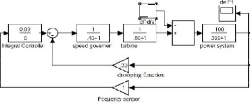
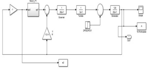
1. A single area power system is used as the simple systems consist of power system block representing the generation transmission, prime-mover and its control. The load disparity has been simulated as step change. The transfer function model has been constructed using MATLAB simulink (10). The system component blocks used in transfer function model are simplified from the differential equations of the system (2-4). The whole functions are used in s domain only.
The different transfer functions used are speed governor, turbine and power system function.
Speed Governor Transfer Function =
Turbine Transfer Function =
Power System Transfer Function =
Speed Regulation =
With integral action, the controller output is proportional to the amount of time the error is present. Integral action eliminates offset(7).
X1 = -K1∑(Erdt)
Where
X1 = output integrating controller
K1 = integrating gain or action factor of the controller
Dt = time sample
The PID controller produces an output related with the summarized deviation between the set point and measured value and integrating gain or action factor. PID controller apt to reply slowly at first, but over a long period of time they tend to reduce errors. The integral controller reduces the steady- state error.
The frequency deviation ∆F is studied using MATLAB Simulink as shown in Fig. 1.
Fig 1 (Single Area Power System using PID control)
III. INTERCONNECTED POWER SYSTEM
detailed electrical frequency(1)(11). The Interconnection shown in our model is shown in Fig. 2 with each subsystem comprising of single phase system shown in Fig. 1
Fig 2(Interconnected Generator Two area System)
IV. WIND TURBINE GENERATOR DEREGULATED SYSTEM
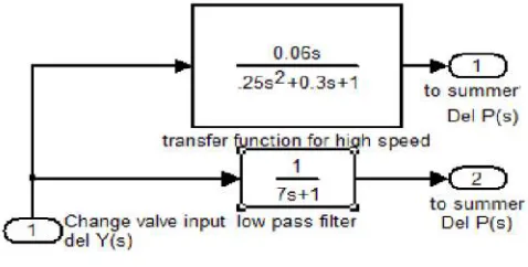
By studying the dynamic performance of wind power generators, more insight is obtained concerning the capability of a wind farm to give frequency control. It is liberated on any other power system and it is functioning as a deregulated system here. A WTG is designed using the system parameters given (8). The two transfer functions are used here for low pass filter andfor high wind speed. This time constant depends on the average wind speed, but is assumed constant for this basic model
Fig 3(Transfer Function of WTG)
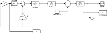
Fig4.(Single Area Power System with WTG and Integral Controller)
V. FUZZY CONTROLLER
The inherent features of the changing loads, difficulty and multi-variable conditions of the power system limits the conventional control techniques giving adequate solutions. Artificial intelligence based gain scheduling is an anothermethod commonly used in designing controllers for non-linear systems. Fuzzy system converts a human knowledge into mathematical formula. Therefore, fuzzy set theory based approach has developed as a complement tool to mathematical approaches for solving power system difficulties. Fuzzy control is dependupon a logical system called fuzzy logic which is must closer in spirit to human thinking and natural language than classical logical systems. Nowadays fuzzy logic is used in nearly all sectors of industry and science. One of them is AGC. The fuzzy logic controller designed for the system analysis is shown in Fig5.
Fig 5(Fuzzy Logic Controller)
The fuzzy logic controller is consist of four main components (1).: the fuzzification, the interface engine, the rule base, and the defuzzification. The several components are present for the in depth study of the system. The fuzzifier converts the numeric/crisp value into fuzzy sets: hence this operation is called fuzzification. The corefactor of the fuzzy logic controller is the interface engine, which makes all logic operations in a fuzzy logic controller. The rule base comprises of membership functions and control rules. Finally, the result of interface process is an output of the fuzzy logic controller should be a numeric/crisp value. Thus, fuzzy set is transformed into a numeric value by using the defuzzifier. This operation is called defuzzification.
The control signal is given by(6)
U (t) = -(kpy+kiʃydt)
Kp and Kiare the proportional and the integral gains respectively and taken equal to one. For the proposal study,
LN: large negative
MN: medium negative,
SN: small negative,
Z: Zero
SP: small positive,
MP: medium positive,
LP: large positive
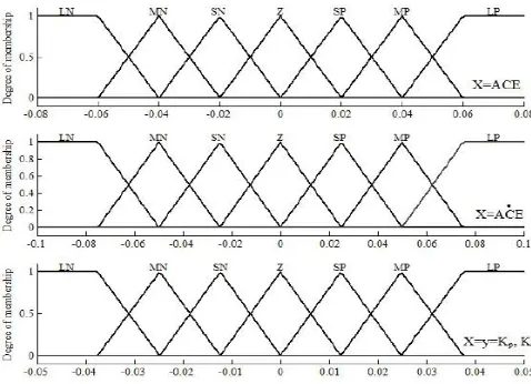
Fuzzy logic shows understanding and preference through membership functions which have different shapes. These rules are based on experiments of the process step response, error signal, and its time derivative (1). The membership
functions of the fuzzy logic pi controller presented in fig 7 comprises of three membership functions (two -inputs and one-output) (1). Respective membership function has seven memberships comprising two trapezoidal and
five triangular memberships
Fig 6(Membership Functions used in the study)
Seven numbers of rules have been taken in inference mechanism. Therefore, 49 control rules are used for this study. The range of X is chosen from simulation results. All memberships are chosen to define the linguistic variables. These functions have different shapes depending on system. For the determination of the control rules, it
ACE A
C E
LN MN SN Z SP MP LP LN LP LP LP MP MP SP Z MN LP MP MP MP SP Z SN SN LP MP SP SP Z SN MN
can be more convoluted than membership functions, which depend on the designer experiences and actual physical system. The control rules are based from if-then statement (i.e if input 1 and input 2 then output 1). Table 1 taken from(1), shows the appropriate rule base used in the study. Let us consider the fourth row and fifth column in Table 1 e.g. if ACE is Z and ACE is SP then y is SN.
The system is now demonstrated with Fuzzy Controller and fuzzy-PID controller implementation in single area network shown in fig. 7, 8. Then implemented to three area interconnected System.
Fig 7(Single Area Power System with Fuzzy Controller and WTG)
Fig 8( Single Area Power System with Fuzzy Controller, Integral Controller and WTG)
VI. HIGH VOLTAGE DC TRANSMISSION
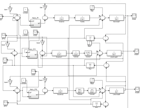
Fig 9 (Three Area Power System with Fuzzy Controller, Integral Controller and WTG)
The system in fig 9 displayed the complete final model with three areas interconnected system using Fuzzy-PID as a controller.
The linearized model of a three-area interconnected system including the dynamic of power modulation controller of HVDC link is shown through equation (12). It should be noted that the power modulation output of HVDC link (˄PDC), performing positively on an area, reacts negatively on another area in an interconnected system. ∆PDC, thus,
flows into both areas with different sign (+, -), at the same time. The time constant TDCof proportional controller is
set appropriately at 0.05 sec in the simulation study (12). The matrix used for stimulation study is (12)
where S is the system matrix (12-13). The variables and parameters are defined as follows: ∆ ƒ1, ∆ƒ2are frequency
deviations of areas 1 and 2 respectively. ∆PACis an AC tie line power deviation between areas 1 and 2. ∆PDCis a
power modulation by HVDC link.∆P12is the total tie line power deviations (∆PAC + ∆PDC). M1, M2 are inertia
constants of areas 1 and 2. D1, D2 are checking coefficients of areas 1 and 2. A12 is an area capacity ratio between
areas 1 and 2. Then system decoupled into two systems and for one system values are expressed in terms of matrix as (13)
By eigen value assignment method, the feedback control scheme of ∆PDC can be expressed as (13).
The values of constants are taken from reference (1) and (13).
VII. SYSTEM DATA(4, 13)
Three area and wind turbine generator data used for the system study in this paper has been given in Table II and III:
Table II Parameters of Subsystems
Parameters of Area 1 & 2 Kp1 Kp2 Kp3 Power System Gain 100
Tp1 Tp2 Tp3 Power System time
Constant
20
Ksg1 Ksg2 Ksg3 Governor Gain 1
Tsg1 Tsg2 Tsg3 Governor Time Constant 0.4
Kt1 Kt2 Kt3 Turbine Gain 1
Tt1 Tt2 Tt3 Turbine Time Constant 0.5
R1 R2 R3 Speed Regulation Droop 3
B1 B2 B3 Frequency Sensor Gain 0.425 Ki1 Ki2 Ki3 Integral Controller Gain 0.09 Kdc1 Kdc2
Kdc3
HVDC System Gain 1
Tdc1 Tdc2 Tdc3
HVDC Time Constant 0.2
Table III Parameters of Wind Turbine Generators (3)
Parameter
Tlow1 Tlow2 Tlow3 7.0 sec T01 T02 T03 0.5 sec D1 D2 D3 0.3 Khigh1 Khigh2 Khigh3 0.006
VIII. SIMULATION RESULTS
In the paper, a deregulated WTG has been used along with integral, fuzzy logic controller and HVDC link to control the load frequency of the power system. The implementation worked with Matlab-Simulink software with simulation time 50 sec. The values of system parameters as clarified above are used for all simulations to facilitate a comparative study.
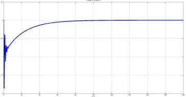
In figure 10, the tuning of the delta-F1 of Area 1 is displayed and in figure 11 the Area two tuning is shown. The frequency deviation plot of both the areas with controller is tuned quite fast with not much spikes.
Fig 11: ∆F2(s) vs. time(s) of Area 2
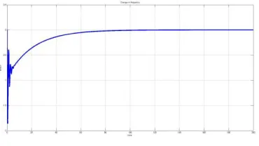
The frequency deviation plot vs. time for subsystems model is studied. First case is without any controller, HVDC and WTG. Then these are used one by one and parallel obtain frequency deviation plot with 1% disturbance in load. The simulation results indicate that the settling time, steady state error and peak overshoot is reduced using WTG, integral and fuzzy controller alone and the different combination of these show even better results as shown in figs.
Fig 11: vs time(s) of Area1 model with integral controller and fuzzy controller
Figure 11, 12 and 13 displays the result for the proposed technique with FUZZY-PID controller. Here the tuning of the system is quite swift and error is quite reduced.
The figure 12 and 13 shows the P vs time for area 2 &3 with Fuzzy-PID controller. Herein if we see the steady state error, settling time and peak overshoot is quite reduced. Tuning is much more improved as compared to only PID controller.
Fig 13: vs time(s) of Area3 model with integral controller and fuzzy controller
IX. CONCLUSIONS
The system with the Fuzzy controller and HVDC planned to improve the dynamic performance of the interconnected three area power system in deregulated environment has been studied. Fuzzy and Fuzzy-PID controller, WTG and HVDC have been coordinated for feasibility study by implementing it to the interconnected three area system, which can be engaged for multi-area problems. It has been saw that responses of frequency deviation with Fuzzy Controller and WTG are well in terms of steady state error, settling time, transients. Simulation results presented justify the use of Fuzzy Controller in deregulated environment for the supply of reliable and quality power.
REFERENCES
1. YogendraArya, Narender Kumar, Hitesh DuttMathur,”Automatic Generation Control in Multi Area Interconnected Power System by using HVDC Links” IJEDS(International Journal of Power Electronics and Drive System) Vol.2, No.1, March 2012, pp67-75, ISSN: 2088-8694 2. I.J Nagrath and D.P. Kothari, “Modern Power System Analysis” 3rd Edition, Sixteenth reprint 2009, Tata Mc-Graw Hill publication. 3. http://onlyengineering.wordpress.com/2012/06/26/thesis-1-automatic-gereration-control-age-part-1/
4. Glenn V.Hicks, “An Investigation of Automatic Generation Control for an Isolated Power System” Master Thesis of Memorial University of Newfoundland, September 97.
5. Manuel A. Matos, “The Fuzzy Power Flow Revisited”. IEEE Transactions on Power Systems, Vol.23 No. 1, February 2008. 6. “ Fuzzy Logic with Engineering Applications”, Third Edition 3rd Edition by Timothy J. Ross
7. http://www.engineeringoolbox.com/process-controllers-d-499.html
8. Jorris Soens, Johan Driesen, Ronnie Belman, “Equilvalent Transfer Function for a Variable Speed Wind Turbine in a Power System Dynamic Simulations” International Journal of Distributed Energy Resources ,Vol. 1 ,Number 2, ISSN 1614-7138, Pp 111-131.
9. http:/nptel.iitm.ac.in/courses/Webcourse-contents/IIT%20Bombay/Power%20System%20Operation%20and%20Control/Module%207/L01-Introduction%20to%20Deregulation-1.pdf
10. A.R. Abhyanker.S.AKhaparde, “Introduction to deregulation in power industry”. Report by Indian Institute of Technology, Mumbai 11. www.mathworks.com/products/matlab- For MATLAB help with Simulink
12. Peter Meisen, “Cross-Border Interconnections on Every Continent” Report by Global Energy Network Institute (GENI), June 2010.
13. Ngamroo, “ A Stabilization of frequency oscillation in a parallel ac-dc interconnected power system via an HVDC Link,” Science Asia, vol. 28, pp. 173-180, 2002
15. K.R. Padiyar, “HVDC Power Transmission Systems”, New Age International(P) Limited Publishers, Second Edition, 2012
16. P. Muley, S. Satyanarayana and V. Kumar, "A fuzzy logic based approach for economic power generation in thermal power plants," Electrical, Electronics, Signals, Communication and Optimization (EESCO), 2015 International Conference on, Visakhapatnam, 2015, pp. 1-5. doi: 10.1109/EESCO.2015.7253631