Solar PV Fed DC Motor Speed Control Using
Microcontroller Based Power Electronic
Controller
Sneha M. Dalavi, Prof. Shubhangi S. Landge
ME Student, Department of Electrical Engineering, All India Shri Shivaji Memorial Society, Institute of Information
Technology, Kennedy Road, Pune, India
Professor , Department of Electrical Engineering, All India Shri Shivaji Memorial Society, Institute of Information
Technology, Kennedy Road, Pune, India
ABSTRACT: In this paper an attempt is made to design and fabricate IC MPPT algorithm using PIC microcontroller for
PV array, so that it will extract maximum available solar power used for charging the battery. Incremental conductance MPPT using direct control method is used in such a way that duty cycle of boost converter is adjusted inside the algorithm. Thus, there is no need to use any other control loop. Incremental Conductance (IC) gives a better performance, faster tracking time and has no oscillation. The hardware makes use of Solar panel, boost converter, battery, PIC 16F877A microcontroller, speed sensor and MOSFET for speed control of PMDC motor using electronic armature voltage control method. Motor is tested for set speed of 500- 1500RPM under load and no load conditions. It has been seen that PI controller will maintain the speed of motor up to given set speed by increasing or decreasing voltage applied across armature of motor.
KEYWORDS: MPPT, DC Motor, Incremental Conductance, PV array.
I. INTRODUCTION
to distribute a maximum power. Some common DC-DC converter topologies for implementing MPPT are Buck converter, Boost converter, Cuk converter and Buck Boost converter.
The paper is organized as follows. Section II presents Incremental conductance MPPT method in detail. Section III presents block diagram of solar PV fed DC motor speed control using microcontroller based power electronic controller. Section IV presents simulation and results of solar PV fed DC motor speed control system. Section V presents hardware implementation and results of solar PV fed DC motor speed control system. In section VI conclusions and future scope are summarized.
II. INCREMENTAL CONDUCTANCE MPPT
PV arrays voltage-current characteristics are non linear, at one unique point the power produced is maximum. This point depends on the temperature of the solar panel and on the irradiance conditions. Both conditions change throughout the day and are also different depending on the seasons in the year. Further irradiation can vary rapidly due to changing atmospheric conditions like clouds. It is important to find the maximum power point precisely under all possible atmospheric conditions so that the maximum power can be obtained. To produce maximum power out of photovoltaic modules MPPT (Maximum power point tracking) system is used. MPPT is an electronic system which varies the electrical operating point of PV modules so that the PV modules are capable of delivering maximum available power.
Incremental Conductance was designed based on an observation of P-V characteristic curve as shown in fig 2.1 below. IC tries to improve the tracking time and to produce more energy on a vast irradiation changes environment. This method is based on the fact that slop of the PV array power curve is zero at the MPP, increasing on the left of the MPP and decreasing on the right hand side of MPP.
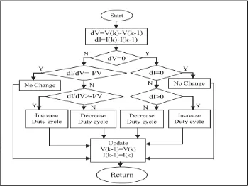
The flowchart of incremental conductance algorithm is shown in Fig2.2 below. The algorithm starts by taking present values of I(k) and V(k) and using previous values stored at the end of the prior cycle, I(k-1) and V(k-1), then verify whether the voltage variable is zero, if it is zero then verify whether the current variable equals zero. If the current variable is also zero, then it means that PV is operating at the maximum power point, so the conductance should remain same and there is no need to change duty cycle
Two other verifications are included to detect whether a control action is required when the array was not operating at the maximum power point; in this case the change in the atmospheric conditions is detected using (dI ≠ 0). Now the control signal adjustment depend on whether dI is positive or negative, if the incremental change in current is positive, the duty cycle should be increased, otherwise it should be decreased.
On the other hand if there is a condition where the voltage variable is not zero, thus verification is carried out by comparing dI/dV with –I/V. According to the result of this verification, the control reference signal adjusted in such a way that array terminal voltage can be moved towards maximum power point voltage. At the maximum power point when dI/dV equal to –I/V, no control action is needed. If dI/dV is greater than –I/V then duty cycle should be increased, otherwise it should be decreased.
Fig 2.2: flowchart of incremental conductance algorithm
III. BLOCK DIAGRAM OF SOLAR PV FED DC MOTOR SPEED CONTROL SYSTEM
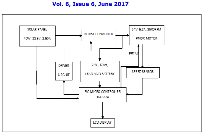
Fig 3.1: Block diagram of solar PV fed DC motor speed control system
Solar panel output is given to the boost converter, so that boost converter will boost the input DC voltage to 24V DC to charge the batteries. Now the battery output is given to PMDC motor. The duty cycle of boost converter is changed by using IC MPPT algorithm. The algorithm is written in the microcontroller programming. This MPPT will allow the maximum available solar power to the boost converter for battery charging purpose.
The PMDC Motor is connected to the DC drive. This DC drive is connected to the PIC microcontroller which is connected to the Diode-Transistor Optocoupler for speed sensing. The Optocoupler provides the rpm feedback to the controller. Controller compares the set speed with actual speed and produces the error signal. The PI controller will make this error zero by increasing or decreasing the voltage across the armature of motor. If the actual speed is greater than the set speed, the PI controller will decrease the firing angle of the MOSFET resulting in decrease in armature voltage. If actual speed is less than the set speed, then the PI controller will increase the firing angle resulting in increase in voltage across the armature, so that the desired set rpm can be achieved. The display shows set speed, actual speed, Vslr, Islr, Vbatt, Ibatt . The firing angle of MOSFET is controlled by the driver circuit.
IV. SIMULATION AND RESULT OF SOLAR PV FED DC MOTOR SPEED CONTROL USING
MICROCONTROLLER BASED POWER ELECTRONIC CONTROLLER
Fig 4.1: The Simulink diagram of solar PV fed DC motor speed control system
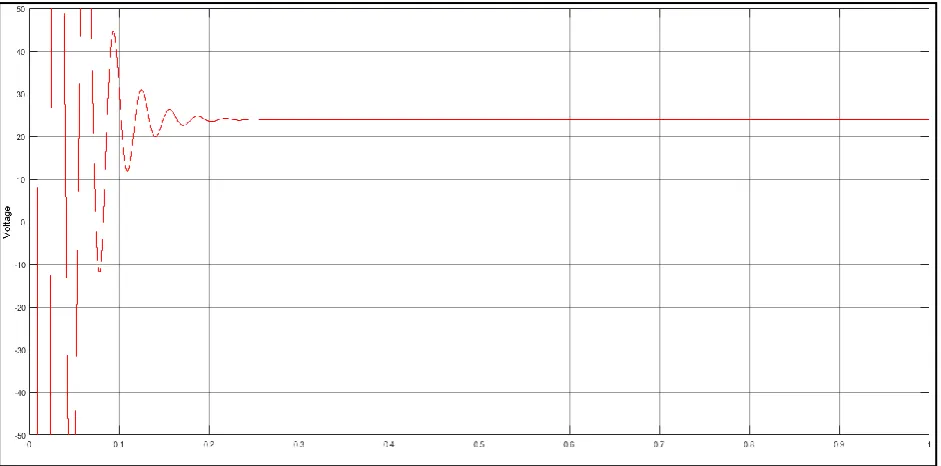
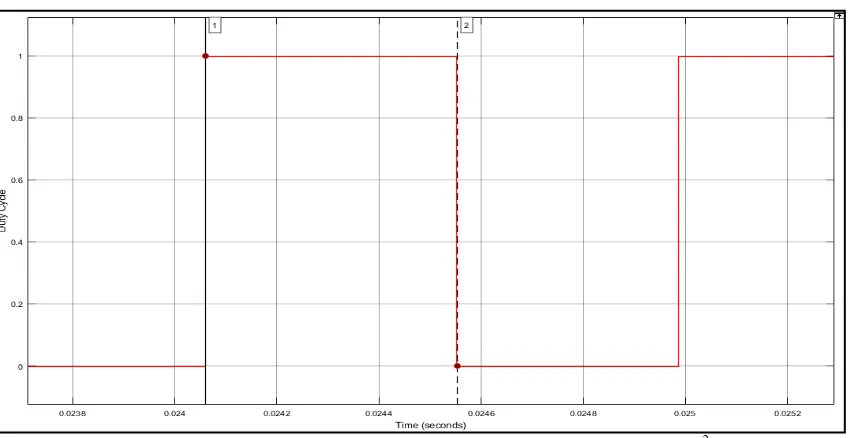
First irradiation 800W/m2 is given to solar array, gives the boost output as 23.93V and duty cycle as 0.56, where on time of
MOSFET is 493.085µS. It is shown in fig 4.2 and fig 4.3 respectively.
Fig 4.3: Duty cycle of boost converter when solar irradiation is 800 W/m2
Then irradiation 1000W/m2 is given to solar array, gives the boost output constant as 23.93V and duty cycle as 0.57, where
on time of MOSFET is 711.002 µS. It is shown in Fig 4.4 and Fig 4.5 respectively
Fig 4.5: Duty cycle of boost converter when solar irradiation is 1000 W/m2
From above simulation results it is clear that Incremental conductance algorithm adjusts the boost converter duty cycle as the solar irradiation changes to give constant 24V DC to charge the battery. Also duty cycle is increased as solar irradiation
increases from 800 W/m2 to 1000 W/m2
V. HARDWARE IMPLEMENTATION AND RESULTS OF SOLAR PV FED DC MOTOR SPEED CONTROL
SYSTEM
This section discusses about hardware implementation and its results. The circuit diagram of hardware setup for solar PV fed DC motor speed control is shown in Fig 5.1 below. The hardware makes use of Solar panel, boost converter, battery, PIC 16F877A microcontroller, speed sensor and MOSFET for speed control of PMDC motor using electronic armature voltage control method. The display shows set speed, actual speed, Vslr, Islr, Vbatt, Ibatt.The firing angle of MOSFET is
controlled by the driver circuit. The hardware set up is shown in fig 5.2
Fig 5.2: Hardware set up for solar PV fed DC motor speed control using microcontroller based power electronic controller
A procedural detail of hardware working is as follows:
Set speed and values of proportional and integral constant is fed in to the PIC through its programming. We can set
the values of speed and values of proportional and integral constant by using INC (increment) and DEC (decrement) keys.
Once these values fed into the PIC16F877A, solar panel output is given to the battery through boost converter as
well as motor. During day period, when sunlight is available, PV output will charge the battery as well as feeds the motor. During the night period, solar panel and boost converter are isolated from circuit and battery will feeds the motor.
Incremental conductance MPPT is used to optimize the solar panel output power. Its algorithm is written in PIC
microcontroller programming. According to this algorithm, duty cycle of boost converter is modified through driver circuit.
Boost converter will boost the I/P solar voltage from 17-17.5V to 28V and thus charges the battery. The MOSFET
is used to control the supply voltage to the motor. The speed of the motor is sensed by the speed sensor i.e. Diode Transistor optocoupler. A rectangular bar is attached to the shaft of the motor. As the bar passes through the optocoupler, the signal pulse is generated which is given as a feedback to the PIC16F877A.
The controller compares the set speed with actual speed and generates the error signal. The error is then minimized
by the PI action of controller and accordingly the output is given to the driver circuit of MOSFET. Thus the MOSFET get fired and by controlling its on time, off time; the voltage applied to motor armature is controlled to get desired value of speed.
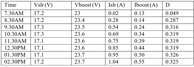
The experimental observations of the battery charging are as follows:
Time Vslr (V) Vboost (V) Islr (A) Iboost (A) D
7.30AM 17.2 23 0.02 0.13 0.049
8.30AM 17.2 23.4 0.28 0.14 0.287
9.30AM 17.3 23.5 0.54 0.24 0.316
10.30AM 17.3 23.6 0.69 0.34 0.319
11.30AM 17.1 23.6 0.75 0.39 0.319
12.30PM 17.1 23.6 0.85 0.44 0.319
01.30PM 17.1 23.7 0.95 0.50 0.326
02.30PM 17.2 23.7 1.04 0.55 0.325
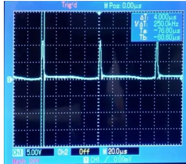
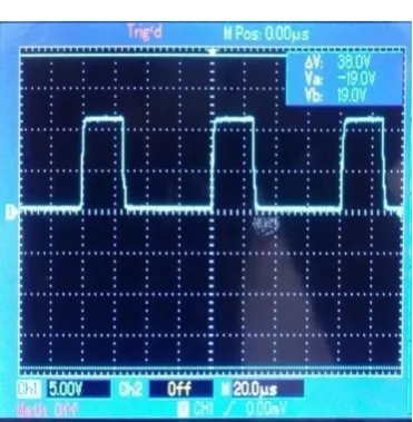
Below DSO screenshots shows the duty cycle waveforms of boost converter at different times of a day.
Fig 5.3: Duty cycle of boost converter at time 7.30AM
Fig 5.4: Duty cycle of boost converter at time 8.30AM
Fig 5.6: Duty cycle of boost converter at time 1.30PM
The experimental observations of the speed control are as follows:
The values of Kp and Ki selected are: Kp=0.5
Ki=0.25
The motor is tested for different values of set speed as shown in Table 5.2 below. The input voltage to motor is varied and corresponding speed of motor is noted down after PI action. The motor is tested under no load condition.
Set RPM Actual RPM DC Voltage across
armature
DC battery voltage applied
600 630 3.9 22.28
700 720 4.55 20.22
800 840 5.50 24.44
900 880 5.86 23.44
1000 990 6.18 22.47
1100 1170 7.44 24.8
1200 1230 7.42 24.73
Table 5.2: Experimental results of speed control of motor on no load
VI. CONCLUSION
In this paper an attempt is made to design and fabricate IC MPPT algorithm using PIC microcontroller for PV array, so that it will extract maximum available solar power used for charging the battery. Incremental conductance MPPT using direct control method is used in such a way that duty cycle of boost converter is adjusted inside the algorithm. Thus, there is no need to use any other control loop. The proposed MPPT method and speed control technique is investigated through simulations and validated experimentally on a laboratory prototype.
VII. FUTURE SCOPE
1. A fuzzy logic control (FLC) can be used to control the maximum power point tracking (MPPT) for a photovoltaic (PV)
system.
2. Tachogenerator can be employed in place of Diode Transistor optocoupler to increase the accuracy of speed feedback.
REFERENCES
1. HabbatiBellia, Ramdani Youcef, Moulay Fatima, ‘‘A detailed modeling of photovoltaic module using MATLAB,’’ NRIAG Journal of Astronomy and Geophysics (2014) 3, 53–61
2. A Safari, S. Mekhilef, ‘‘Implementation of Incremental Conductance method with Direct Control, ’’TENCON 2011, 2011 IEEE
3. RatnaIkaPutria, Sapto Wibowob, Muhamad Rifa, ‘‘Maximum power point tracking for photovoltaic using incremental conductance method, ’’ 2nd International Conference on Sustainable Energy Engineering and Application, ICSEEA 2014
4. M.Lokanadham,K.VijayaBhaskar, ‘‘Incremental Conductance Based Maximum Power Point Tracking (MPPT) for Photovoltaic System,’’ International Journal of Engineering Research and Applications (IJERA) Vol. 2, Issue 2, Mar-Apr 2012
5. Aleck W. Leedy, LipingGuo, Kennedy A. Aganah, ‘‘A Constant Voltage MPPT Method for a Solar Powered Boost Converter with DC Motor Load, ’’ 2nd International Conference on Sustainable Energy Engineering and Application, ICSEEA 2014
6. PongsakorTakun, SomyotKaitwanidvilai, ChaiyanJettanasen, ‘‘Maximum Power Point Tracking using Fuzzy Logic Control for Photovoltaic Systems, ’’ Proceedings of the International MultiConference of Engineers And Computer Scientists 2011 Vol II, IMECS 2011, March 16- 18, 2011, Hong Kong
7. Lalam S. Sindhura, KalpanaChaudhary, ‘‘Artificial Neural Network Implementation for Maximum Power Point Tracking of Optimized Solar Panel, ’’ International Journal of Computer Applications (0975 – 8887) Volume 78 – No.10, September 2013
8. S.Krithiga, N.AmmasaiGounden, ‘‘A Microcontroller based Power Electronic Controller for PV assisted DC motor Control, ’’ 2013 6th International Conference on Industrial and Information Systems, ICIIS 2013, Aug. 16-19, 2013, Sri Lanka
9. Aruna. K, Pravin. M. R, Ramachandran. J, Sudheer. S ,Sathiyasekar. K , ‘‘Design and Implementation of PI Controller for the Speed Control of DC Motor in Cooling System,’’ International Journal of Engineering Trends and Technology (IJETT) – Volume 9 Number 5 - Mar 2014
10. RupaliNazar, ‘‘Improvement of Efficiency of Solar Panel using different methods, ’’International Journal of Electrical and Electronics Engineers, Volume 07, Issue 01, Jan- June 2015
11. http://www.autospectator.com/cars/files/images/Photovoltaic-Cell.jpg 12. http://en.wikipedia.org/wiki/Photovoltaic_array