www.ijiset.com
The Effect of Different Fuels on the Performance of A SCRAM Jet
Engine: A Thermodynamic Analysis
Venkata Hanuma Sai Teja T1
1
MSc Aerospace Engineering, Brunel University, London
Abstract
The SCRAM jet engine is an evolution of the ram jet engine, capable of flying at speeds well above Mach 5. This work consists of mathematically formulating and studying the performance parameters such as Specific Impulse and Specific Thrust over a wide range of Mach numbers. Hydrogen, Methane and Kerosene were used as fuels. The First Law of Thermodynamics and Stream Thrust Analysis were used to determine pressure, temperature and velocity at each station. Assumptions were stated and followed. Other important parameters such as the stream thrust function and cyclic static temperature ratio were discussed. It was observed that Hydrogen produced the highest specific impulse and specific thrust while methane and kerosene produced lesser results.
Keywords: SCRAM jet engine, First Law, Stream Thrust Analysis Specific Impulse, cyclic static temperature ratio.
1. Introduction
Scram jet is used when speeds of over Mach 6 are to be achieved. A ram jet engine can reach a speed of only Mach 5-6, this limit is due to the normal shock before the combustion chamber. In a ram jet engine the speed is reduced to subsonic before it can enter into the combustor for combustion. Due to the dissociation effects at higher speeds, the incoming air is maintained at supersonic through the use of an oblique shock, this evolution in the engine is called SCRAM Jet engine (Supersonic Combustion Ram jet engine). Due to the absence of any moving parts, neither ram jet engine nor the scram jet engine need to be axisymmetric. [1][7][8]
1.1 Schematics of a SCRAM Jet Engine
Figure 1 RAM Jet Engine [7]
Like the jet engine, the ram jet or the scram jet engine consist of the same type of components. Fig-1, 2
1) Diffuser: The diffuser consists of a convergent geometry that slows the speed of the intake air. The air is compressed based on the inlet velocity, pressure and the geometry of the diffuser. In a ram jet engine, at the end of diffuser (compression) a normal shock occurs, slowing the speed of the incoming air to subsonic. While in a scram jet engine, an oblique shock occurs, slowing the intake air while maintaining supersonic speeds.
2) Burner: The air entering the burner is slowed to subsonic or supersonic based on the engine configuration. Here, fuel is mixed and burned. This adds to the energy of the incoming air.
3) Nozzle: The air from the combustion chamber enters the nozzle where it is expanded using a convergent-divergent geometric configuration. The air leaving the nozzle is several magnitudes higher is velocity than the incoming air. The difference in these speeds provides the propulsion needed for the aircraft.
Figure 2 SCRAM Jet Engine [7]
For a SCRAM jet engine, the velocity of air in the above mentioned components is always maintained at supersonic speeds.
Nomenclature
Pressure at reference station ‘i’(mPa)
Temperature at reference station ‘i’ (K)
Velocity at reference station ‘i’ (m/s)
Thrust(N)
Fuel flow rate(kg/s)
Acceleration due to gravity(m/s^2)
Specific Impulse(s)
Heating value of fuel(kJ/kg)
Specific Thrust(m/s)
Overall efficiency
Propulsive efficiency
Efficiency of the ‘i’ component
Mach number at ‘i’ station
Cycle static temperature ratio
Entropy at ‘i’ station
Heat Capacity(kJ/K)
Gas constant(kJ/kgK)
Stoichiometric fuel/air ratio
Stream Thrust Function
2. Component Modelling of SCRAM Jet
Figure 3 SCRAM Jet Engine Components [1]
Table 1 Components of SCRAM Jet engine
Reference station
Engine Location
0
Free stream Conditions
External compression begins
1
External compression ends
Internal compression begins
Inlet or diffuser entry
3
Inlet or diffuser exit
Internal compression ends
Burner or combustor exit
4
Burner or combustor exit
Internal expansion begins
Nozzle entry
9
Internal expansion ends
Nozzle exit
External expansion begins
10 External expansion ends
The numbers mentioned in table 1 are standard for a SCRAM jet engine and have been widely used. The missing numbers in between account for additional components such as injectors, mixers etc if used [8].
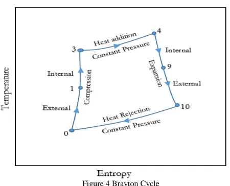
2.1 Ideal Brayton Cycle
Figure 4 Brayton Cycle
Figure.4 shows an ideal Brayton cycle. The process of compression, combustion and expansion within the engine is treated as the above cycle. The respective points represent the start and end of the processes. [1][7][8] Point 0-3 represents the compression in the engine. As seen in reference [1] [8], the cyclic static temperature, which is the ratio of the burner entry static temperature to the freestream temperature, was prioritized. The compression was taken to be adiabatic and isentropic. Point 3-4 represents the process of heat addition. This process involved fuel addition without the addition of mass. Only the constant pressure heat addition was studied in this work.
Point 4-10 represents the process of expansion. This was taken as adiabatic and isentropic.
www.ijiset.com
2.2 Assumptions
The calculations in his work were done with some assumptions. The following are stated below. [1][7][8]
a) The working fluid was a pure substance and it
was always in an equilibrium state. [7] [8] b) The working fluid returns to its original state after
the process.(Heat rejection process) [7]
c) The whole system was treated as a control volume
without any interactions with the surfaces. The system was treated as one-dimensional problem. [7]
d) Combustion takes place only at constant pressure
and dissociation effects were neglected. [7]
e) The mixing of the fuel is uniform and complete
combustion of the fuel takes place. [7]
f) All the fuels were considered to be in their
gaseous state. [8]
2.3 General Methodology
The present work consists of thermodynamically analyzing a SCRAM jet engine by using the mathematical formulation of the First law of thermodynamics [8] and a concept of thrust-work potential called Stream Thrust [4]. Venkata [1] has done work using first law analysis and stream thrust analysis of a SCRAM jet engine at different altitudes. A simple Brayton cycle was used to study the performance parameters of the engine, including the study of efficiencies [10]. The system was divided into components and sub-systems to evaluate parameters at individual stations. More advanced methods such as treating the whole vehicle in terms of explicit second-law characteristics, considering the whole system as a stream tube have been studied [2]. The performance of the system in terms of thrust and propulsive losses in terms of entropy have also been studied [3].
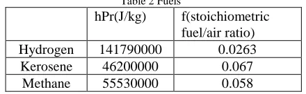
In this work, different fuels were used to study the variation of study variables such as stream thrust etc. The fuels used in the study were,
Table 2 Fuels
hPr(J/kg) f(stoichiometric
fuel/air ratio)
Hydrogen 141790000 0.0263
Kerosene 46200000 0.067
Methane 55530000 0.058
Hydrogen, Kerosene and Methane were used in the study of performance of the SCRAM jet engine.
Formula for stoichiometric combustion [11]
(1)
Thee stoichiometric combustion equation for methane. (2)
3. Analysis
The following definitions play an important role in defining the performance of a SCRAM jet engine [1] [8] [9],
Specific Thrust - It is the ratio between uninstalled thrust and the entry mass flow rate
(3)
Specific Impulse - Ratio of uninstalled thrust and fuel weight flow.
(4)
Overall Efficiency -Ratio of thrust power to chemical energy release rate of fuel.
(5)
Propulsive Efficiency - Ratio of the thrust power to the engine mechanical power.
(6)
3.1 First law analysis
First law analysis was used to study variable parameters at different stations along the SCRAM jet engine. The parameters in study were temperature, pressure and entropy. Due to the flow nature, an independent variable called the cyclic static temperature was used to determine the maximum allowable compression temperature. The mathematical formulation for the analysis was taken from [8]
(7)
1580 K was taken as the maximum allowable compression
temperature [8]. The burner entry Mach number, which is
a co-dependent variable on the cyclic static temperature, was formulated as
(8)
Table 3 Input Values for First Law (Hydrogen)
Input for First Law
M0 6
Gamma 1.4
Speed of Sound 298.663 m/s
V0 1791.978 m/s
T0 222 K
T3 1580 K
ψ 7.117117
nb.fhPr/Cp0.T0 16.78487
nc 0.9
nb 0.9
300 kg/s
ne 0.9
Cp0 1000 J/kg K
Cpc 1090 J/kg K
Cpb 1510 J/kg K
Cpc.Re/Rc.Cpe 0.722
Cpe 1510 J/kg K
Rc(air) 287 J/kg K
Re(air) 287 J/kg K
fhPr 4140268 J/kg
R0(air) 287 J/kg K
3.2 Stream Thrust
Due to the nature of analysis, the first law does not account for the fluctuations due to mass, momentum and energy. In order to study the effects of these fluxes (with some
assumptions) a parameter called the Stream Thrust
Function was used. The Stream Thrust Function is derived
from the momentum relations of the one-dimensional approach used in this work. [8]
The mathematical approach in this work considered the averaged values at different stations. Parameters such as the static pressure at station 10 was considered equal to the free stream pressure. This was to ensure the full expansion
of the flow. In usual case, the flow may have
over-expanded or under-expanded. The stream thrust function
was defined as
(9)
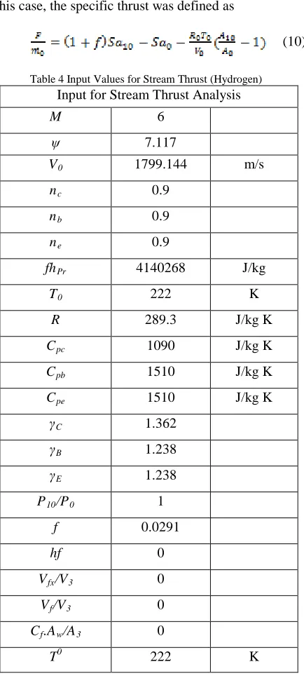
In this case, the specific thrust was defined as
(10)
Table 4 Input Values for Stream Thrust (Hydrogen)
Input for Stream Thrust Analysis
M 6
ψ 7.117
V0 1799.144 m/s
nc 0.9
nb 0.9
ne 0.9
fhPr 4140268 J/kg
T0 222 K
R 289.3 J/kg K
Cpc 1090 J/kg K
Cpb 1510 J/kg K
Cpe 1510 J/kg K
γC 1.362
γB 1.238
γE 1.238
P10/P0 1
f 0.0291
hf 0
Vfx/V3 0
Vf/V3 0
Cf.Aw/A3 0
T0 222 K
4. Results and Discussions
This work discusses the effect of different fuels on the parameters such as propulsive efficiency, specific thrust and specific impulse. The Input values were taken from table 3 and table 4 [1].
4.1 Propulsive Efficiency
www.ijiset.com
the use of hydrogen as the fuel provides the engine with most efficiency, followed by methane and kerosene.
Figure 5 Propulsive Efficiencies of Different Fuels (FL)
A similar trend was observed in Stream Thrust analysis, Fig-6. Due to the nature of assumptions, the graphs of Stream Thrust analysis and First Law are slightly different. For a preliminary analysis, this was acceptable.
Figure 6 Propulsive Efficiencies of Different Fuels (ST)
4.2 Specific Impulse
Specific impulse is a parameter used to measure the propulsion of a rocket. But due the speeds encountered by the SCRAM jet engine, it was used here as a study parameter. Fig-7 shows the specific impulse of the analysis using First Law for different fuels. It was seen that the use of Hydrogen as fuel gives higher specific impulse compared to Methane or Kerosene. This is due to the higher heating value of Hydrogen. Methane has the second highest heating value of the three fuels considered in this analysis therefore the analysis using methane as fuel showed the second highest specific impulse characteristics. Specific Impulse was observed to decrease with Mach number.
Figure 7 Specific Impulse of Different Fuels (FL)
A similar trend is seen with the use of Stream Thrust analysis for different fuels as shown in Fig-8.
Figure 8 Specific Impulse of Different Fuels (ST)
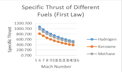
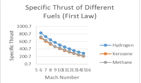
4.3 Specific Thrust
Figure 9 Specific Thrust of Different Fuels (FL)
stated figures pertaining to graphs, both the heating value and efficiency were seen to be highest for hydrogen while methane and kerosene were lower. Fig-10 shows the specific thrust of the engine while using Stream Thrust Analysis.
Figure 10 Specific Thrust of Different Fuels (ST)
5. Conclusions
A simple analysis of a SCRAM jet engine using the First Law of Thermodynamics and Stream Thrust analysis was done in this study. The main variable in this study were fuels. Hydrogen, Methane and Kerosene were used. It was seen that hydrogen produced the most effective results while methane and kerosene produced lower values. It was also observed that hydrogen and methane produced almost similar results in the Stream Thrust Analysis. This was due to the difference in parameters affecting the specific impulse and specific thrust. The parameter ‘fHpr’, which is the combination of heating value of fuel and stoichiometric fuel/air ratio are similar for hydrogen and methane. Due to nature of assumptions, a variation was seen in a comparative study between first law and stream thrust analysis of the engine. For a more accurate analysis, an in-depth understanding of the supersonic combustion parameters as well as better assumptions would yield valuable results. This work provides a simple framework for further studies to work on.
Acknowledgement
The author likes to thank Dr. Lionel Ganippa from
Brunel University, London, for his input during the author’s study.
REFERENCES
[1]. Venkata Hanuma Sai Teja T, 2016. A Preliminary Study of SCRAM Jet Engine using Stream Thrust Analysis and First Law at Different Altitudes, International Journal
of Research in Engineering and Technology, Vol. 05,
Issue-07, pp. 13-18
[2]. David J Riggins, T. T. D. J. M., 2006. Methodology for Performance Analysis of Aerospace Vehicle Using the Law of Thermodynamics. Journal of Aircraft.
[3]
.
Foa, J., 1960. Elements of Fligth Propulsion. New York: Wiley[4]. Edward T Curran, C. R., 1973. The Use of Stream Thrust Concepts for the Approximate Evaluation of
Hypersonic Ramjet Engine Performance. U.S Air Formce
Aero-Propulsion Lab, Issue TR-73-38
[5]. B, R., 2001. Comparison of Thermodynamic Loss
Models Suitable for Gas Turbine Propulsion. Journal of
Propulsion and Power, Vol. 17, No. 2, pp. 324-332.
[6]. B, R., 2002. A Work Potential Perspective of Engine
Component Performance. Journal of Propulsion and
Power, Vol. 18, No.6, pp. 1183-1190.
[7]. Valentina Amati, C. B. D. S. E. S., December 2006. Development of a Novel Modular Simulation Tool for teh Exergy Analysis of a Scramjet Engine at Cruise Condition.
International Journal of Thermodynamics Volume 9, pp.
1-11.
[8]. William H.Heiser, D. T., 1985. Hypersonic
Airbreathing Propulsion. s.l.:AIAA
.
[9]. Jiang Qin, W. Z. W. B. D. Y., 2010. Thermodynamic analysis and parametric study of a closed Brayton cycle
thermal management system for scramjet. Internation
Journal of Hydrogen Energy, pp. 356-364
[10]. Wen Bao, J. Q. W. Z. D. Y., 2009. Parametric Performance analysis of multiple Re-Cooled Cycle for
hydrogen fuelled scramjet. International Journal of
Hydrogen Energy, pp. 7334-7341.
[11]. Fry, R. S., 2004. A Century of Ramjet Propulsion
Technology Evolution. Journal of Propulsion and Power.
[12]. Combustion Fundamentals (2016, July 15). Retrieved http://authors.library.caltech.edu/25069/4/AirPollution88-Ch2.pdf
Biography
Venkata Hanuma Sai Teja T : Independent Researcher
![Figure 2 SCRAM Jet Engine [7]](https://thumb-us.123doks.com/thumbv2/123dok_us/7856844.1303144/1.612.337.525.447.541/figure-scram-jet-engine.webp)