State Estimation and Determination of Flexibility Potential in
Medium Voltage Networks
∗
Florian Rewald†1,Oliver Pohl1,Ulf Häger1, andChristian Rehtanz1
1 TU Dortmund University, 44227 Dortmund, Germany
Abstract.This paper describes how flexibility of medium voltage systems can be used for operation of high voltage systems. This is explained using the example of a congestion management system for high voltage networks developed in the research project IDEAL. First, it is explained to what extent flexibility is required for high voltage system operation. After that, the entire congestion management system with flexibility of medium voltage systems is presented. Then, methodology for observability analysis, state esti-mation and determination of flexibility potential is shown. Finally, the implementation of the methodology in two real medium voltage systems is described.
1
Introduction
Due to climate change many countries try to limit the production of greenhouse gas emissions. In Ger-many the production of greenhouse emissions will be reduced by 85 % until 2050. This is one reason, why the energy system is aimed to be transformed sus-tainably and all coal fired power plants will be shut down by 2038 and even all nuclear power plants until 2022. The existing large fossil and nuclear power plants will be replaced by many small distributed energy re-sources (DER) and by large off shore wind farms. This means not only a change of energy supply, it is also a change of the structure of the entire energy sys-tem. The large number of DER with small installed capacity is mostly connected to medium voltage (MV) or low voltage (LV) networks, which implies a shift of energy supply from transmission and sub-transmission systems to distribution systems. Off Shore wind farms feed into the transmissions networks as the most fossil power plants, but the distance to the load centres in West and South of Germany is much bigger than the distance between the fossil power plants and the indus-try regions toady.
Furthermore, the feed-in of photovoltaic (PV) power plants and wind farms is strongly weather-dependent. In addition, power lines and transformers are over-loaded due to the lack of network expansion to this day. This leads to an increased need for balancing en-ergy in the entire enen-ergy system.
This balancing energy is mostly provided by fossil power plants, which will be shut down in a few years. Therefore, DER must also provide flexibility in the fu-ture. This means a higher coordination effort between
distribution system operator (DSO) and transmission system operator (TSO), which has not yet occurred. Furthermore, MV and LV networks are only designed for load cases and not for injection cases. LV networks are normally fixed coupled via a transformer to a MV network and not equipped with measurement devices for estimating system state. Finally, feasible flexible generation units are mostly not equipped with com-munication technology.
The use of flexibility in high voltage (HV) system op-eration requires an estimation of MV system state and an approach for determining flexibility potentials. Ap-proaches for estimating system state considering spe-cific requirements of distribution systems are presented in [1] or [2]. The optimal localization of measurement devices for estimating system state is analysed e.g. in [3]. The determination of flexibility potential of dis-tribution systems is addressed e.g. in [4], [5] or [6]. Thereby, it is often assumed that distribution systems are fully observable.
This paper presents a practical approach for determin-ing flexibility potential of MV for HV system operation considering incomplete observability of MV systems. In this case flexibility means all feasible set points of MV systems at connecting point to HV system, which can be provided without violating any network restric-tions. Set point of the distribution system can be changed by changing the set points of flexible gener-ation units. Flexibility options are needed to provide the demand of flexibility in HV systems. In this case all DER connected to MV systems are considered as flexible generation units and all DER can provide flex-ibility.
∗This work was supported by the German Federal Ministry for Economic Affairs and Energy (BMWi) in the course of the project IDEAL (FKZ: 03ET7557A).
The main goal of this paper is to show how flexibil-ity of distribution systems can be used for HV sys-tem operation. This is explained using the example of HV congestion management system (CMS) with flexibility of MV systems. This is part of research project Impedance Controllers and Decentralized gestion Management for Autonomous Load Flow Con-trol (IDEAL)1. This project focuses on developing an
agent-based HV congestion management system based on distributed power flow controller (DPFC) and flex-ibility of underlying MV and LV networks. For this reason, the flexibility potential of the distribution sys-tem is determined based on estimated syssys-tem state. This paper is structured as follows: Section II gives an overview for the use of flexibility from distribution for transmission systems. After that, the entire CMS approach based on DPFC and flexibility of underlying distribution systems is explained in section III. After-wards section IV gives an overview about estimating of system state and determination of flexibility poten-tials. Sections V focuses on the real implementation of the whole system in field test. The paper concludes with an outlook for further research questions.
2
Medium Voltage System Flexibility for
High Voltage Systems
For the operation of an electrical power system flex-ible power is required for frequency stability as well as preventive and curative elimination of network bottle-necks. This section describes in which cases flexibility of MV and LV networks can be used for transmission and sub-transmission systems.
2.1 Flexibility for Frequency Stability
Energy supply and load must be balanced for a con-stant frequency. Within a control area, balancing oc-curs through trading on the electricity power exchange up to a maximum of five minutes before the energy is made available. Due to the increasing installed capac-ity of volatile PV and wind power plants as well as the stochastic behaviour of loads energy feed-in and load in control areas are not balanced in every situation. Therefore, operating reserve is used, which is mostly provided by fossil power plants. Due to the shut down of these power plants, one option for providing operat-ing reserve is the use of flexibility of distribution sys-tems.
2.2 Flexibility for preventive Elimination of Bot-tlenecks
Flexibility is also used preventively to mini-mize potential bottle necks in transmission and sub-transmission systems. Therefore, the injection of two power plants between which the bottleneck is located are increased or respectively decreased. According to the law redispatch is carried out by power plants whose installed capacity is more than 50 MW.
2.3 Flexibility for curative Elimination of Bottle-necks
To eliminate existing bottlenecks and violations of voltage restrictions flexibility of distribution systems can also used in same voltage level as well[7]. In this case it is allowed to regulate loads and injections of DER. This regulated power increased in the last few years and is likely to rise further since the use of load shifting for the network planing process[8]. This means that distribution networks are not designed for all high feed-in peaks. So the feed-in management becomes a tool for the system operation process and the need for flexibility increase.
2.4 Research Questions
From the perspective of MV and LV system opera-tor the following questions have to be addressed:
• In which cases can flexibility of MV systems be used for system operation of HV system?
• How can system state in a MV network be esti-mated?
• How can the flexibility potential be determined based on estimated system state?
• What can a CMS look like across both voltage levels?
• What influence do measurement inaccuracies and large measurement errors have on the system state?
• How can pseudo measurements be determined based on metro logically developed substations for substations without measurement devices?
• How can the injection and load at substations be forecast depending on the weather?
• Can an ideal number and placement of measure-ment devices be derived from the previous inves-tigations?
The main goal of this paper is to give an overview of the CMS from the perspective of DSO. The aim is to describe how the questions described above can be an-swered within the framework of the project, not giving an answer to all these questions.
3
Congestion Management System with
Flexibility of Distribution Systems
G
G G
Agent Smart Telecontrol
Unit
Telecommunication Gateway
Flexible Unit G
Control Centre
!
HV
MV
Figure 1: Overview of developed CMS [9]
The main goal of the research project IDEAL is to develop an agent-based congestion management sys-tems for HV system with DPFC and flexibility of underlying distribution systems. An overview of the whole system is visualized in figure (1). The figure con-sists of the levels control centre, HV and MV systems is intended to explain the components of the system and elimination of the shown bottleneck. A detailed description can be found in [9].
3.1 Distributed Power Flow Controller
The used DPFC are so called Distributed Series Reactors (DSRs). These devices consists of a coil and have the capability of injecting inductance or capaci-tance into the power line. So the reaccapaci-tance of power lines can increase or decrease and power flow can be controlled in a meshed system to eliminate bottleneck. These devices are directly clipped on the overhead power line. First installation and field tests of DSR have been already done in 2012. If the bottleneck can-not be eliminated by DPFC flexibility of underlying MV systems will be used.
3.2 Flexibility of Medium Voltage Systems Flexibility of MV systems can be used for eliminat-ing existeliminat-ing bottlenecks in HV system. At the request of the HV system operator, MV systems operator has to change the active and reactive power flow at the con-nection point between HV and MV systems. Thereby, network restrictions of MV and LV systems have not been violated. The methodology of determining sys-tem state, flexibility potential and implementation in field test are described in sections IV, V and VI.
3.3 Hardware Components
To coordinate the DPFC and the use of flexibility potentials hardware devices are used. Smart Telecon-trol Unit (STU) are installed at every transformer sta-tion. On these devices the multi agent system (MAS) for agent communication is hosted. Furthermore, every flexible MV system is equipped by Telecontrol Gate-way (TCG). On these gateGate-ways, flexibility potential is calculated based on incoming measurement values.
3.4 Centralized and Decentralized Control Strate-gies
Due to the high number of decentralized units in further energy systems, decentralized and autonomous control strategies based on MAS are used for the pro-posed CMS. MAS gives just a recommendation to control centre for eliminating the existing bottlenecks. Due to high security requirements for system operation and for research purposes, MAS is also implemented in control centre to compare results of MAS and control centre for eliminating bottlenecks.
3.5 Information Flow and Decision Making An agent is implemented on a STU in every HV/MV transformer station. The power lines and flexible MV systems are assigned to one agent. The agent gets voltage and current measurement of as-signed power lines with DPFC and flexibility potentials of assigned MV systems. Agents share status informa-tion to each other at every time. In case of overloaded line assigned agent inform the other agents. Now every agent determines a negotiation of actions for eliminat-ing network bottleneck and sends it to the assigned agent, which decide for one negotiation of action. Dur-ing autonomous mode agent executes the best negotia-tion of acnegotia-tion, otherwise it sends the recommendanegotia-tion to control centre and waits for further introductions.
4
Estimation of System State and
Deter-mination of Flexibility Potential
4.1 Observability Analysis
To Estimate system state a sufficient number of measured values as well as a homogenous location in the system is required. Observability analysis deter-mines, whether the number and location of the avail-able measured values in a network is sufficient for the calculation of a complex voltage at every single node. The observability can be expressed as a non-linear vec-tor equation hobs depending on measurement vectorz
and system state vectorxobsas shown in (1).[10]
hobs(xobs) =z (1)
Thereby, vector xobs consists of branch voltage and
phase angle variables α1, α2 and αl as well as δ1, δ2
and δl. l is the number of branches. These variables
are determined by (2) and (3) for any branchj.
αj =ln
Vk
Vm
(2)
δj=θk−θm (3)
Thereby,kandmare nodes which branchjconnected. In the next step (1) is approximated with the Taylor series in (4).
Hobs·∆x=z−fobs(x0) = ∆z (4)
whereHobs=∂hobs∂x(xobs)
obs and∆xobs=xobs−x
0
obs. The
Jacobian matrix consists of branch variables and mea-surement equations. Meamea-surement equations contain all measurement values expressed as non linear func-tion of branch variables of voltageαand phase angles δ.
Jacobian matrix is decomposed into its triangular fac-tors with Peters-Wilkinson method. Zero pivots of up-per triangular matrix are substituted by 1.0. This is equivalent to adding a new measurement value. To solve equation (4) for x. All non zero entries of x correspond to the unobservable branches. Further ap-proaches for observability analysis are described in [10].
4.2 State Estimation
The main goal of state estimation (SE) is the de-termination of a consistent system state. System state is defined as complex voltage at every single node. In transmission and sub-transmission systems SE based on weighted least square (WLS) approach is commonly used. The correlation between system state vector x = [f2...fne1...en] and measurement vector z is not
linear since nodal voltages and power flows do not cor-relate linearly to each other. Thereby, n is the total number of buses. The functionhdefines the non linear network equations of each measured value as a function of the state vector. These measured values are subject to a measurement errore. [10], [11]
z(x) =h(x) +e (5)
The estimation of the measurement error is deter-mined in such a way that the sum of all weighted squared errors is minimized. The weighting matrixR is a diagonal matrix of the measurement errors. The weighting is inversely proportional to the varianceσii
of measurement error.
J(x) =
m X
i=1
(zi−hi(x))2
Rii
!
=min (6)
Equation (6) can be solved iteratively by Gauss-Newton approach, including the calculation ofH, be-ing the Jacobian matrix ofh.
To increase redundancy nodes can be considered whose injection and load is zero. Nodal power of these nodes is with high probability zero, so variance of measure-ment error becomes very small. Therefore, solving equation 5 can have numerical problems. These numer-ical problems are considered by Hachtel´s Augmented Matrix Approach (HAM). The numerical problems are considered by this approach with separation into con-straints. [12]
4.3 Determination of Flexibility Potential
Based on system state flexibility potential can be determined. Flexibility potential means all feasible set points of MV systems at the connection point to HV system without neglecting any network restrictions.
4.3.1 Determination of Flexibility Potential based with Monte Carlo Simulation
Determination of flexibility potential by random variation of energy supply and load is presented in [5]. The set points of flexible feeders and loads are ran-domly changed and it is checked by power flow calcula-tion whether a set point of the distribucalcula-tion system can be found without violating any network restrictions. Furthermore, it is proven that the set of all feasible set points can be described as an area.
4.3.2 Optimization Method
5
Implementation of the flexibility
deter-mination in real MV systems
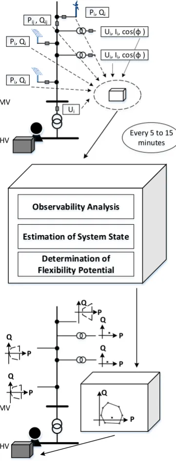
Figure 2: Overview field test
Observability Analysis
Estimation of System State
Determination of Flexibility Potential
Ui, Ii, cos(φ )
Pi, Qi
Ui, Ii, cos(φ )
Pi, Qi
Pi, Qi
Pij , Qij
Ui
Every 5 to 15 minutes
Q
P Q
P
P Q
Q
P MV
HV
MV
HV
Q
P Q
P
This section describe the implementation of SE and determination of flexibility potential in real MV sys-tem. The entire system is shown in figure (2).
5.1 Measurement Devices
To increase redundancy of measurement values and to test the developed methodology two MV systems are equipped with measurement devices as shown in figure (2). These measurement devices are installed in MV/LV substations and measure three-phase voltage amount, current amount and power factor. In addition,
the measured values of the DER connected to MV sys-tems can be used. There are no power flow and phasor measurement unit (PMU) measurements currently in use. If available, these measurement values can also be used. The measured values are transmitted via Power Line Communication or wireless.
Depending on measurement devices measured values are averaged values over a period of five minutes. Oth-erwise, measured values are current values, where a minimum and maximum value is also specified within the period. Measured values of DER are current values without any further information. They are transmitted every 15 minutes.
5.2 Determination of Flexibility Potential
To determine the flexibility potential, it is first analysed whether the network topology can be fully observed with the available measured values. If the system is not observable, system state cannot be esti-mated and flexibility potential cannot be determined. The MV systems considered in the field test can be observed by the installed measurement technology and pseudo measurement values. Nevertheless, this can change if a measurement device or the communication network fails. In this case, further measured values can be added, pseudo measured values can be used or the network topology can be simplified. Observability analysis is only performed if there have been modifica-tions in the measured value configuration or the net-work topology.
If the network is observable, SE can be executed and complex voltages can be determined on every single node. In the following step, complex nodal power is calculated using complex nodal voltages. These nodal voltages are input data to the algorithm for determin-ing the flexibility potential with the known maximum and minimum active and reactive power limits of flex-ible generation units. No nodal power is calculated at the slack node. This nodal power is determined as flex-ibility potential during the next step. Flexflex-ibility po-tential is calculated by an optimization approach based on OPF and developed for this application. These al-gorithms have a modular structure so that different methods can be used for SE and determination of flex-ibility potential.
5.4 Field Test
The described approach will be tested over a period of six months in two MV networks. In these networks, certain parts are completely equipped with measure-ment devices. The test is over a period of six month in order to test the functionality of the algorithms and availability of communication technology on the one hand and to investigate flexibility at different seasons on the other hand. The measured values as well as the calculated system states and flexibility potentials are documented for research purposes. The presented sys-tem for determining flexibility potentials can also be used regardless of CMS. This could be cases which are described in section II.
During the field test only estimating of system state and determination of flexibility potential can be tested. Flexibility cannot be requested, so the set point of two MV systems cannot be changed. The components of HV system are tested by hardware-in-the-loop simula-tion in laboratory.
6
Further Research Questions and
Out-look
This sections gives a short outlook to further re-search questions.
6.1 Determination of Pseudo Measurement for non measuring substations
Set points of substations with measurement devices are to be analysed and checked to what extent pseudo measurements values for stations without measurement technology can be obtained. This is intended to reduce the number and costs if measurement devices. Further-more, an optimal placement of measurement devices can be determined from this data.
6.2 Forecast of Flexibility Potential
System operation of HV systems requires not only flexibility potential at the current point in time, but also for future points in time. The existing measure-ments values of different substations are therefore to be investigated for correlation with weather data.
References
[1] A. Primadianto and C. Lu, “A review on distribu-tion system state estimadistribu-tion,”IEEE Transactions on Power Systems, vol. 32, no. 5, pp. 3875–3883, 2017.
[2] J. Wu, Y. He, and N. Jenkins, “A robust state esti-mator for medium voltage distribution networks,” IEEE Transactions on Power Systems, vol. 28, no. 2, pp. 1008–1016, 2013.
[3] R. Singh, B. C. Pal, and R. B. Vinter, “Measure-ment place“Measure-ment in distribution system state
esti-mation,” IEEE Transactions on Power Systems, vol. 24, no. 2, pp. 668–675, 2009.
[4] H. Chen and A. Moser, Eds., Improved flexibil-ity of active distribution grid by remote control of renewable energy sources: 2017 6th International Conference on Clean Electrical Power (ICCEP), 2017.
[5] D. Mayorga Gonzalez, J. Hachenberger, J. Hinker, F. Rewald, U. Häger, C. Rehtanz, and J. Myrzik, “Determination of the time-dependent flexibility of active distribution networks to control their tso-dso interconnection power flow,” in 2018 Power Systems Computation Conference (PSCC), 2018, pp. 1–8.
[6] D. A. Contreras and K. Rudion, Eds., Improved Assessment of the Flexibility Range of Distribution Grids Using Linear Optimization: 2018 Power Systems Computation Conference (PSCC), 2018. [7] B. Bauernschmitt, R. Palaniappan, D. Hilbrich,
and C. Rehtanz, “Modular configurable and testable automation architecture for future active electrical energy grids: 2018 53rd international universities power engineering conference (upec).” [8] C. Wagner, Integration und Bewertung der Spitzenkappung als Planungsgrundsatz zur wirtschaftlichen Netzentwicklung in Mittelspan-nungsnetzen, 1st ed., ser. Dortmunder Beiträge zu Energiesystemen, Energieeffizienz und En-ergiewirtschaft. Herzogenrath: Shaker, 2019, vol. 6.
[9] O. Pohl, F. Rewald, S. Dalhues, P. Jörke, C. Re-htanz, C. Wietfeld, A. Kubis, R. K. Tamgue, and D. Kirsten, “Advancements in distributed power flow control,” in2018 53rd International Universi-ties Power Engineering Conference (UPEC), 2018. [10] A. Abur and A. G. Exposito,Power System State Estimation: Theory and Implementation, ser. Power Engineering (Willis). Hoboken: Marcel Dekker Inc, 2004.
[11] E. Handschin, Elektrische Energieübertra-gungssysteme, 2nd ed., ser. ELTEX. Heidelberg: Hüthig, 1987.
[12] G. Bei, “Observability analysis for state estima-tion using hachtel’s augmented matrix method,” Electric Power Systems Research, vol. 77, no. 7, pp. 865–875, 2007.
![Figure 1: Overview of developed CMS [9]](https://thumb-us.123doks.com/thumbv2/123dok_us/7994064.1327117/3.595.88.264.123.487/figure-overview-of-developed-cms.webp)