95 | P a g e
STRUCTURAL STRENGTH COMPARISON OF RCC
AND STEEL FRAME STRUCTURE AND MODELING
IN MULTIPLE BIM DIMENSION
Kurupudi Mounika
Civil Engineering, Aditya College of Engineering Technologies.(India)
ABSTRACT
Today’s cities reveal skies punctuated by buildings so tall and austere, even architectural tour guides experience the occasional pain in the neck. So, which material reigns supreme in the world of development today - concrete or steel? Both provide numerous benefits. Building Information Modeling (BIM) has become an essential part of any design project by facilitating smarter, faster, stronger designs that make economic sense while reducing environmental impact. BIM provides support every step of the way from design and visualization, to simulation and construction. This software AUTODESK REVIT richest software for BIM its helps teams collaborate, innovate, and connect with clients in more productive ways.
This project aims that preparing completestructural strength comparison between RCC and Steel design of frame. The analysis of a structural frame excitation is an essential step in the design of a structure to resist earthquake seismic response and wind simulation of a RCC and steel frame is analyzed by the linear analysis approaches of Equivalent Static Lateral Force and Response Spectrum methods using STAAD.Pro& ROBOT STRUCTURAL ANALYSIS Professional 2017software as per the IS- 1893-2002-Part-1and IS875-part-3.IS:875(1987)code of practice for design loads (other than earth quake)for buildings and structures Part 1dead loads, Part 2 imposed loads, Part 3 wind loads, Part 5 Combinations, IS 1893(part 1):2002 criteria for earthquake resistance.
Finally compare the structural strength of G+20 RCC frame structure with Steel frame structure. Modeling in multiple BIM dimension by using Autodesk Revit software as requirement 1D, drawing 2D, BIM 3D to communicate the design intent, 4D cad or what happens to the schedule in case of project. 5D cad or what happens to the cost in case of project, 6D cad or how to optimize the energy consumption. 7Dcad or how to manage assetslife cycle.
Keywords- BIM Softwares, Lateral Loads, 7D modelling, RCC Design, Steel Design.
I.INTRODUCTION
96 | P a g e
While designing a building for its survival under seismic actions, following factors must be taken into consideration.
Type of construction material (concrete or steel)
Type of structure (rigid or ductile)
Configuration of the load resisting structural system to control response of building.
What is BIM?
• BIM is a process to plan, design, construct and manage a project based on an intelligent digital prototype, developed prior to construction and coordination through the model during the project life cycle.
BIM helps us to plan, design, construct and manage the buildings and infrastructure virtually insight.
Fig1: Transfer from 3D to 7D
II.ANALYSIS AND RCC DESIGN OF STRUCTURAL FRAME SUBJECTED TO WIND
AND SEISMIC FORCES
97 | P a g e
Fig5: RCC design results for beam in ROBOT structural analysis professional 2017software.
2.1The structural strength details of RCC frame
Floor Details Member No Bending moment (kN.m) Shear force (kN) Displace ments (mm) Axial forces (kN) Torsion (kNm)
98 | P a g e
14th floor 869 88.441 51.63 0.650 536.56 -0.110 15th floor 905 89.664 52.56 0.750 558.23 -0.160 16thfloor 987 90.556 54.12 0.900 578.25 -0.230 17th floor 999 90.999 55.36 1.200 598.32 -0.350 18th floor 1002 91.023 59.48 1.560 601.23 -0.440 19th floor 1038 92.347 60.78 1.580 613.00 -0.560 20th floor 1110 93.555 61.65 1.590 625.89 -0.567 21th floor 1198 94.112 65.23 1.990 630.12 -0.567
Table1:Analysis results of RCC frame fromROBOT structural analysis professional 2017software.
III. ANALYSIS AND STEEL DESIGN OF STRUCTURAL FRAME SUBJECTED TO
WIND AND SEISMIC FORCES.
99 | P a g e
Fig8: Stresses developed in ROBOT structural analysis professional 2017software.
Fig9: Steel connection details in ROBOT structural analysis professional 2017software.
3.1The structural strength details of Steel frame.
Floor
Details
Member
No
Bending
moment
(kN.m)
Shear
force
(kN)
Displace
ments
(mm)
Axial
forces
(kN)
Torsion
(kNm)
100 | P a g e
3rd floor 295 80.540 -25.56 0.079 66.78 0.794 4th floor 303 81.483 41.33 0.112 168.58 0.457 5th floor 396 81.766 16.89 0.115 315.65 0.165 6th floor 410 81.970 54.89 0.147 168.36 0.799 7th floor 487 82.970 65.31 0.554 652.58 0.649 8th floor 515 82.643 15.78 0.454 187.14 0.797 9th floor 576 83.897 79.85 0.445 365.45 0.948 10th floor 610 84.162 45.41 0.454 187.36 0.698 11th floor 714 85.795 64.02 0.112 274.85 0.879 12th floor 789 86.977 13.36 0.454 167.20 0.697 13th floor 823 86.645 56.89 0.797 368.00 -0.792 14th floor 869 87.445 98.63 0.797 271.56 -0.498 15th floor 905 88.457 46.56 0.164 624.23 -0.191 16th floor 987 89.464 54.12 0.978 287.25 -0.989 17th floor 999 89.974 55.36 1.775 268.32 -0.979 18th floor 1002 90.654 56.48 1.487 688.23 -0.964 19th floor 1038 91.787 65.78 1.145 726.00 -0.981 20th floor 1110 92.974 89.65 1.899 726.89 -0.478 21th floor 1198 93.797 16.23 1.644 981.12 -0.698
101 | P a g e
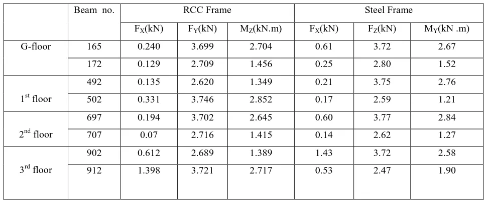
3.2Structural Strength comparison between RCC and Steel frame.
Column no.
RCC Frame Steel Frame
FX(kN) FY(kN) MZ(kN.m) FX(kN) FZ(kN) MY(kN .m)
G-floor
229 82.968 0.211 0.561 52.05 0.24 0.37 237 64.309 0.230 0.611 66.34 0.29 0.43 1st floor 485 46.423 0.358 0.669 38.60 0.51 0.79 487 61.246 0.322 0.597 48.60 0.65 1.02
2nd floor
691 28.326 0.541 1.260 25.28 0.44 0.67 683 39.606 0.470 1.092 32.40 0.51 0.80
3rd floor
1017 8.934 0.651 1.270 12.46 0.69 0.87 1025 5.250 0.748 1.469 16.24 0.85 1.08
Table 3: analysis comparison for columns
Beam no. RCC Frame Steel Frame
FX(kN) FY(kN) MZ(kN.m) FX(kN) FZ(kN) MY(kN .m)
G-floor 165 0.240 3.699 2.704 0.61 3.72 2.67 172 0.129 2.709 1.456 0.25 2.80 1.52
1st floor
492 0.135 2.620 1.349 0.21 3.75 2.76 502 0.331 3.746 2.852 0.17 2.59 1.21
2nd floor
697 0.194 3.702 2.645 0.60 3.77 2.84 707 0.07 2.716 1.415 0.14 2.62 1.27
3rd floor
902 0.612 2.689 1.389 1.43 3.72 2.58 912 1.398 3.721 2.717 0.53 2.47 1.90
Table 9.2 : analysis comparison for beams
IV.PLANNING-2D
The Plot Area of shopping mall is 216’10” * 165’10”. The Carpet Area of shopping mall is 12856 Sq ft. The Plinth Area of shopping mall is 14309 sq ft. Floor Space Index (FSI)=0.39.
102 | P a g e
V.MODELLING-3D
5.1Autodesk RevitArchitecture
Autodesk Revit Architecture is a robust architectural design and documentation softwareapplicationcreatedbyAutodeskforarchitectsandbuildingprofessionals.The tools and features that make up Revit Architecture are specifically designed to support building information modelling (BIM) workflows.
5.1Basement & Ground floorplans
Fig10:Description of basement floor plan
The Basement Parking refers to parking located below grade within an occupied building.
Ground floor is divided into wine gallery and Kirana&cosmetics.
5.2 First,Second and Third floorplans
103 | P a g e
One side consists of Electronics stuffs and the other side is used for Gamingzone. Electronics deals with equipment intended for everyday use, typically in private homes. Consumer electronics include devices used for entertainment (flat screen TVs, DVD players, DVD movies,
iPods, video games, remote control cars, etc.), communications (telephones, cell phones, e-mail-capable
laptops,etc.) 5.4Exterior Designing
Fig 27: Description of side view
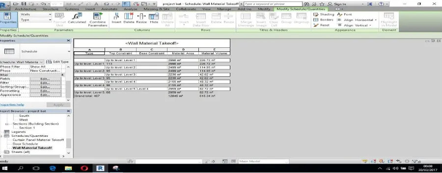
VI.SCHEDULING
6.1Bill ofquantities
A bill of quantities (BOQ) isA bill of quantities (BOQ) is a document used in tendering in the constructionindustry in which materials, parts, and labour (and their costs) are itemized. It also (ideally) details the terms and conditions of the construction or repair contract and itemizes all work to enable a contractor to price thework for which he or she isbidding.
104 | P a g e
Category Count Dimensions Material Volume(cum)
Column 1 450×600 mm RCC 0.99 Total column 100 450×600 mm RCC 99 Exterior wall 1 315mm Generic Wall 106.63 Interior wall 1 1 105mm Basic generic wall 51.02 Interior wall 2 1 140mm Block work 74.66 Floor 1 4381 sq.m In-situ concrete 296.74
Table3: Description of scheduling of basement floor.
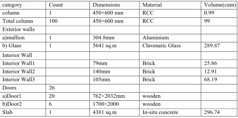
category Count Dimensions Material Volume(cum) column 1 450×600 mm RCC 0.99
Total column 100 450×600 mm RCC 99 Exterior walls
a)mullion 1 304.8mm Aluminium
b) Glass 1 5641 sq.m Chromatic Glass 289.87 Interior Wall
Interior Wall1 79mm Brick 25.86 Interior Wall2 140mm Brick 12.91 Interior Wall3 105mm Brick 68.19 Doors 26
a)Door1 20 762×2032mm wooden b)Door2 6 1700×2000 wooden
Slab 1 4381 sq.m In-situ concrete 296.74 Table 7 Description of scheduling of Third floor
Finally, the overall estimates of all floors in the shopping mall has been given in a tabular form which is given below
.
S.no Floors Total cost Rupees 1 Basement Floor 2077250
2 Ground Floor 5255162 3 1stFloor 5298366 4 2ndFloor 5254032 5 3rdFloor 5453161 Total Cost 23337971 /-
105 | P a g e
VII.SUSTAINABLE RESULTS-6D &FACILITY MANAGEMENT-7D
s
Repo
Building Performance Factors
Energy Use Intensity ,Life Cycle Energy Use/Cost
Annual Carbon Emissionsand Annual Energy Use/Cost
106 | P a g e
Monthly Heating Load and Monthly Cooling Load
Monthly Fuel Consumption and Monthly Electricity Consumption
107 | P a g e
Annual Wind Rose (Frequency Distribution)
108 | P a g e
Monthly Design Data and Annual Temperature Bins
Diurnal Weather AveragesHumidity
Renewable Energy Potential
VIII. CONCLUSION
Analysis of the structural RCC and Steel frame is completed by using ROBOT structural analysis 2017 software against wind and seismic loads. The results obtained from ROBOT analysis are compared for the better construction material.
The steelstructural members are super-quick to build at the site,as a lot of work can be pre-fabbed at the factory and the RCC structural members can endure very high temperatures from fire for a long time without loss of structural integrity.