585-313-110 108647413
Intuity™ CONVERSANT® System
Version 7.0
Copyright and Legal Notices
Copyright Copyright © 2000 by Lucent Technologies. All rights reserved.
Printed in the USA.
This material is protected by the copyright laws of the United States and other countries. It may not be reproduced, distributed, or altered in any fashion by any entity (either internal or external to Lucent Technologies), except in accordance with applicable agreements, contracts or licensing, without the express written consent of the Business Communications Systems (BCS) Global Learning Solutions (GLS) organization and the business management owner of the material.
Copyright and Legal Notices
• CLEO Communications — Trademarks: LINKix.
• Hayes Microcomputer Products, Inc. — Trademarks: Hayes, Smartmodem.
• Intel Corporation — Registered trademarks: Pentium. • Interface Systems, Inc. — Trademarks: CLEO.
• International Business Machines Corporation — Registered trademarks: IBM, VTAM.
• Lucent Technologies — Registered trademarks: 5ESS, AUDIX,
CONVERSANT, DEFINITY, Voice Power. Trademarks: FlexWord, Intuity, Lucent.
• Microsoft Corporation — Registered trademarks: Excel, Internet Explorer, Microsoft, MS, MS-DOS, Windows, Windows NT.
• Minnesota Mining and Manufacturing — Trademarks: 3M. • Netscape Communications — Trademarks: Netscape Navigator. • Novell, Inc. — Registered trademarks: Novell.
Copyright and Legal Notices
• Santa Cruz Operation, Inc. — Registered trademarks: UnixWare. • UNIX System Laboratories, Inc. — Registered trademarks: UNIX. • Veritas Software Corporation — Trademarks: VERITAS.
• Xerox Corporation — Trademarks: Ethernet.
Limited Warranty Lucent Technologies provides a limited warranty on this product. Refer to the “Limited Use Software License Agreement” card provided with your package. Lucent Technologies has determined that use of this electronic data delivery system cannot cause harm to an end user's computing system and will not assume any responsibility for problems that may arise with a user's computer system while accessing the data in these document.
Every effort has been made to make sure that this document is complete and accurate at the time of release, but information is subject to change.
United States FCC Compliance Information
Copyright and Legal Notices
interference, in which case the user will be required to correct the interference at his own expense.
Canadian Department of Communications (DOC) Interference Information
This digital apparatus does not exceed the Class A limits for radio noise emissions set out in the radio interference regulations of the Canadian Department of Communications.
Le Présent Appareil Nomérique n’émet pas de bruits radioélectriques dépassant les limites applicables aux appareils numériques de la class A préscrites dans le reglement sur le brouillage radioélectrique édicté par le ministére des Communications du Canada.
European Union Declaration of Conformity
Lucent Technologies Business Communications Systems declares that the Lucent Intuity CONVERSANT system equipment specified in this document conforms to the referenced European Union (EU) Directives and Harmonized Standards listed below: EMC Directive 89/336/EEC Low-Voltage Directive 73/23/EEC. The “CE” mark affixed to the equipment means that it conforms to the above directives.
Telecom New Zealand Ltd Warning Notices
Copyright and Legal Notices
make or model, nor does it imply that any product is compatible with all of Telecom’s network services.
IMPORTANT NOTICE: Under power failure conditions, this device may not operate. Please ensure that a separate telephone, not dependent on local power, is available for emergency use.
AUTOMATIC RE-ATTEMPTS TO THE SAME NUMBER: Some parameters required for compliance with Telecom’s Telepermit requirements are dependent on the equipment (PC) associated with this device. The associated equipment shall be set to operate within the following limits for compliance with Telecom specifications:
• There shall be no more than 10 call attempts to the same number within any 30 minute period for any single manual call initiation, and,
Copyright and Legal Notices
USER INSTRUCTIONS (AUTOMATIC CALL SETUP): This equipment shall not be set up to make automatic calls to the Telecom "111" emergency service.
CALL ANSWERING (AUTOMATIC ANSWERING EQUIPMENT): Some parameters required for compliance with Telecom’s Telepermit requirements are dependent on the equipment (PC) associated with this device. In order to operate within the limits for compliance with Telecom specifications, the associated equipment shall be set to ensure that calls are answered between 3 and 30 seconds of receipt of ringing.
Toll Fraud Toll fraud is the unauthorized use of your telecommunications system by an unauthorized party, for example, persons other than your company’s employees, agents, subcontractors, or persons working on your company’s behalf. Note that there may be a risk of toll fraud associated with your telecommunications system and, if toll fraud occurs, it can result in substantial additional charges for your telecommunications services.
Your Responsibility for Your System’s Security
Copyright and Legal Notices
prevent unauthorized use of common-carrier telecommunication services or facilities accessed through or connected to it. Lucent Technologies will not be responsible for any charges that result from such unauthorized use.
Lucent Technologies Fraud Intervention and Corporate Security
If you suspect that you are being victimized by toll fraud and you need technical support or assistance, call the Lucent Technologies National Customer Care Center Toll Fraud Intervention Hotline at 1 800 643-2353. Aside from whether immediate support is required, all toll fraud incidents involving Lucent products or services should be reported to Lucent Corporate Security at 1 800 821-8235. In addition to recording the incident, Lucent Corporate Security is available for consultation on security issues,
Copyright and Legal Notices
Documentation Ordering Information
To order a document, contact the Lucent Technologies Publications Center and specify the 9-digit document number, the issue number, and the issue date.
Write, Call, or Fax
Lucent Technologies Publications Center 2855 N. Franklin Road
Indianapolis, IN 46219
Voice 1 800 457-1235 International Voice 317 322-6791 FAX 1 800 457-1764 International FAX 317 322-6699
World Wide Web
Use a web browser to reach one of the following sites. Click Documents and follow the instructions at the site.
• Organizations within Lucent Technologies http://www.cic.lucent.com
Copyright and Legal Notices
Standing Orders
Contents
Copyright and Legal Notices
ii
Copyright. . . .ii
Acknowledgment . . . .ii
Trademarks . . . .ii
Limited Warranty . . . iv
United States FCC Compliance Information . . . iv
Canadian Department of Communications (DOC) Interference Information . . v
European Union Declaration of Conformity . . . v
Telecom New Zealand Ltd Warning Notices . . . v
Toll Fraud. . . .vii
Documentation Ordering Information . . . ix
About This Book
xxvii
Overview . . . . xxviiIntended Audiences . . . xxviii
Contents
Keyboard and Telephone Keypad Representations . . . xxxiv
Cross References and Hypertext . . . xxxv
Screen Displays . . . xxxvi
Other Typography . . . xxxvii
Safety and Security Alert Labels. . . xxxvii
Getting Help . . . . xxxviii
Technical Assistance. . . xxxix
Web Site . . . xxxix
Contact Numbers . . . xxxix
Related Resources. . . xl
Training . . . xl Documentation . . . .xli
Using the CD-ROM Documentation . . . xliii
Contents
Contact Us Directly . . . xlvii
1 Getting Inside the Computer
1
Overview . . . 1
Protecting against Damage from Electrostatic Discharge . . . 2
Removing Power from the MAP/100P . . . 5
Accessing the Circuit Card Cage . . . 9
Replacing the Dress Cover . . . . 11
Restoring Power to the MAP/100P. . . . 11
2 Installing or Replacing Circuit Cards
13
Overview . . . . 13General Procedures . . . . 14
Removing a Circuit Card . . . 14
Installing a Circuit Card . . . 16
Settings for Optional Circuit Cards. . . . 18
Tip/Ring Circuit Cards . . . 19
IVP6-IA (AYC29) Circuit Card . . . 22
Contents
Switch Settings . . . 30
Installing the E1/T1 Circuit Card Driver. . . 32
Speech and Signal Processor (AYC43) Circuit Card . . . 36
Jumper Settings . . . 37
Switch Settings . . . 37
Memory . . . 39
Installing the ASP Driver Package . . . 39
PCI Ethernet LAN Circuit Cards . . . 42
SMC8432 Circuit Card . . . 42
SMC9332 Circuit Card . . . 44
Installing a PCI LAN Circuit Card . . . 45
Replacing a PCI LAN Circuit Card . . . 51
RAID Controller Circuit Card . . . 52
Token Ring Circuit Card . . . 52
IBM Turbo 16/4 . . . 53
Installing the Token Ring Driver . . . 61
Asynchronous SuperSerial Circuit Card . . . 66
Installing the Asynchronous SuperSerial Circuit Card Driver . . . 67
FIFO/SIB Synchronous Host Circuit Card . . . 72
Contents
Verifying the Parameter Settings. . . 80
Video Controller Circuit Cards . . . 98
Remote Maintenance Circuit Card. . . 101
Types of Remote Maintenance Circuit Cards . . . 102
Setting the Resource Options . . . 104
Inserting the Remote Maintenance Circuit Card . . . 105
Installing the Remote Maintenance Circuit Card Software Package . . . 105
3 Replacing the Hard Disk Drive
108
Overview . . . 108Identifying a Failed Hard Disk Drive in a RAID System . . . 109
Removing a SCSI Hard Disk Drive in a RAID System. . . 110
Installing a SCSI Hard Disk Drive in a RAID System. . . 112
Replacing a SCSI Hard Disk Drive in the RAID System . . . 113
Performing a Manual Rebuild of a RAID Array . . . 114
Adding a SCSI Hard Disk Drive to a RAID System . . . 115
Identifying a Failed SCSI Hard Disk Drive in a Non-RAID System . . . 127
SCSI Hard Disk Drive Contents. . . 128
Contents
Hardware Procedures for Replacing a SCSI Hard Disk
Drive in a Non-RAID System . . . 131
Removing a SCSI Hard Disk Drive . . . 134
Installing a SCSI Hard Disk Drive in the MAP/100P . . . 135
Replacing SCSI Hard Disk Drive 0 in a Non-RAID System . . . 136
Replacing SCSI Hard Disk Drive 0 (Nonmirrored System) . . . 136
Replacing the Hard Disk Drive . . . 137
Restoring the Intuity CONVERSANT System . . . 138
Replacing SCSI Hard Disk Drive 0 (Mirrored System) . . . 138
Replacing a SCSI Hard Disk Drive other than Drive 0 in a Non-RAID System . . . 141
Software and Hardware Procedures for Replacing a SCSI Hard Disk Drive (Nonmirrored System). . . 142
Replacing the Hard Disk Drive . . . 142
Restoring the Intuity CONVERSANT System . . . 143
Software and Hardware Procedures for Replacing a SCSI Hard Disk Drive (Mirrored System) . . . 147
Replacing the Hard Disk Drive . . . 148
Contents
Using the fdisk Command . . . 164
Low-Level Formatting the SCSI Hard Disk Drive . . . 167
Low-Level Formatting with a P5 200 MHz CPU Circuit Card . . . 167
Mirroring . . . 169
Establishing Mirroring . . . 169
Removing Mirroring . . . 174
Disk Reuse. . . 175
Reusing for Mirroring . . . 175
Reusing for Speech . . . 175
4 Replacing Other Components
177
Overview . . . 177Replacing Backplanes . . . 178
Replacing the Circuit Card Backplane . . . 178
Removing the Circuit Card Backplane . . . 179
Installing the Circuit Card Backplane . . . 181
Replacing the Power Supply Backplane . . . 182
Removing the Power Supply Backplane . . . 184
Installing the Power Supply Backplane . . . 186
Contents
Replacing the Diskette Cable. . . 193
Removing the Diskette Cable . . . 193
Installing the Diskette Cable . . . 195
Replacing the Console Alarm Cable . . . 196
Removing the Console Alarm Cable . . . 197
Installing the Console Alarm Cable . . . 199
Replacing the Power Cables . . . 200
Replacing the Cartridge Tape and Diskette Drive Power Supply Cable . . . . 200
Replacing the RAID Hard Disk Drive Carriage Backplane Power Supply Cable . . . 203
Replacing the SCSI Hard Disk Drive Carriage Backplane Power Supply Cable in a Non-RAID System . . . 208
Replacing the Circuit Card Backplane Power Supply Cable . . . 212
Replacing the Unit Maintenance Interface Board Assembly Cable . . . 215
Removing the Remote Maintenance Circuit Card Interface Cable . . . 216
Installing the Remote Maintenance Circuit Card Interface Cable . . . 218
Replacing the Reset Cable . . . 221
Removing the Reset Cable . . . 221
Installing the Reset Cable . . . 223
Contents
Replacing the Cartridge Tape Drive . . . 229
Removing a Cartridge Tape Drive . . . 231
Installing a Cartridge Tape Drive . . . 235
Replacing the Console Alarm Panel . . . 237
Removing the Console Alarm Panel . . . 239
Installing the Console Alarm Panel . . . 241
Replacing the Diskette Drive . . . 242
Removing the Diskette Drive . . . 242
Installing a Diskette Drive . . . 244
Replacing a Fan Module . . . 248
Removing a Fan Module . . . 249
Installing a Fan Module . . . 251
Replacing the Fan Filter . . . 252
Removing Fan Filters . . . 252
Cleaning the Fan Filter. . . 253
Installing Fan Filters. . . 254
Replacing the AC Line Fuse . . . 254
Removing the AC Line Fuse . . . 256
Contents
Memory and SIMM Description . . . 262
Identifying a Damaged SIMM . . . 265
Checking for Proper SIMM Seating. . . 265
Checking for Defective SIMMs . . . 267
Removing SIMMs . . . 269
Installing SIMMs . . . 270
Replacing the Internal Power Supply . . . 272
Removing a Power Supply. . . 273
Installing a Power Supply. . . 275
Replacing the Unit Maintenance Interface Board Assembly . . . 276
Removing the Unit Maintenance Interface Board Assembly . . . 277
Installing the Unit Maintenance Interface Board Assembly . . . 278
Replacing a Terminator SIP . . . 279
Replacing the Tip/Ring Distribution Hardware . . . 281
Removing the Tip/Ring Distribution Hardware. . . 283
Installing the Tip/Ring Distribution Hardware. . . 285
Contents
Initializing the Hard Disk Drives . . . 307
Transferring the UnixWare Files. . . 318
Installing the Application Server . . . 319
Activating the Volume Manager . . . 322
Installing the LAN Card Driver Package . . . 323
Setting up the Monitor . . . 323
Initializing the Mouse. . . 328
Testing the Mouse . . . 331
6 Installing the Intuity CONVERSANT System Software
333
Overview . . . 333Installing the Intuity CONVERSANT Base Software Set. . . 333
7 Installing the Optional Feature Software
345
Overview . . . 345Installing Software Packages Using the Unix Management Screens . . . 346
Installing the Global Array Manager Package for RAID Systems . . . 348
Installing the Intuity Hardware RAID Integration Package . . . 350
Contents
Installing the Adjunct/Switch Application Interface Packages . . . 361
Installing the CALLVISOR PC ISDN Package . . . 361 Installing the CALLVISOR PC LAN Gateway Package . . . 364 Installing the CALLVISOR PC ASAI Package . . . 367 Installing the Adjunct/Switch Application Interface Package . . . 369
Installing the Analog Switch Interface Package . . . 373 Installing the Backup/Restore Utility . . . 375 Installing the Call Bridge Application Package . . . 377 Installing the Call Classification Analysis Package . . . 379 Installing the Data Collection Toolkit . . . 382 Installing the Dial Pulse Recognition Package . . . 385 Installing the Enhanced Basic Speech Package . . . 387 Installing the FlexWord Speech Recognition Package. . . 389
Installing the ASP Driver . . . 389 Installing FlexWord Recognition - Base . . . 390 Installing FlexWord Recognition - U.S. English . . . 392
Contents
Installing the cleo_sna_1281u Package . . . 417 Installing the cleo_3270 Package . . . 420 Installing the cleo_mgmt Package . . . 423 Installing the cleo_netman Package . . . 425 Installing the cleo_HTE Package . . . 428 Completing the Installation . . . 430
Installing the Host Packages . . . 431
Installing the Synchronous Host Interface Package . . . 431 Installing the 3270 Enhanced File Transfer Package . . . 433 Installing the NetView Alarm Interface Package . . . 435
Installing the ORACLE Development Packages . . . 437
Package List . . . 438 Installation Requirements . . . 439 Procedures . . . 439 Increasing ORACLE File System . . . 439 Creating a Temporary File System . . . 439 Installing the Intuity ORACLE 7 Pro*C Package . . . 440 Installing the Intuity ORACLE Developer 2000 Toolkit . . . 442
Post Installation Setup . . . 449
Contents
Installing the Advanced Primary Rate Interface Package. . . 457
Installing the Script Builder Package. . . 459 Installing the Script Builder FAX Actions Package . . . 463 Installing the Unix Management Screens Package . . . 471 Installing T1 Packages . . . 473
Installing the Line Side T1 Interface Packages . . . 473 Installing the Line Side T1 Interface Package - Definity . . . 473 Installing the Line Side T1 Interface Package - Galaxy. . . 476 Installing the T1 E&M Package . . . 478
Installing the Text To Speech Package. . . 481 Installing the WholeWord Recognition Packages . . . 488
Installing the WholeWord Recognition - Base Package . . . 488 Installing the WholeWord Recognition - Language Package . . . 490
Contents
Component Assignments . . . 508
Circuit Cards . . . 508 Operating Hardware . . . 512
Hardware Resource Allocator Operation . . . 516
Adding Hardware to an Existing Configuration . . . 517 Removing Hardware from an Existing Configuration . . . 521 Specifying a New Configuration. . . 525 Saving a Configuration. . . 531 Viewing a Configuration . . . 533 Viewing a Successful Configuration . . . 533 Viewing an Unsuccessful Configuration . . . 536 Viewing a Dated Configuration . . . 536 Comparing a Configuration . . . 538 Presetting Hardware Resources . . . 538
Configuration Device Data . . . 541
The show_devices Command . . . 541
Appendix B: Component Ordering Numbers
542
Contents
Checklist for Building a System . . . 551
Appendix D: Disaster Recovery Checklists
553
Disaster Recovery Checklists . . . 553
Checklist for Software Reloading on Nonmirrored Intuity
CONVERSANT Systems with Existing Hard Disk Drives . . . 554 Checklist for Intuity CONVERSANT Systems
with All New Hard Disk Drives . . . 555 Checklist for Nonmirrored Intuity CONVERSANT Systems with a
New Hard Disk Drive 0 and Other Existing Hard Disk Drives . . . 557 Checklist for Nonmirrored Intuity CONVERSANT Systems with a
New Hard Disk Drive, Other than Hard Disk Drive 0. . . 558 Checklist for Mirrored Intuity CONVERSANT Systems with a
New Hard Disk Drive 0 and Other Existing Hard Disk Drives . . . 560 Checklist for Mirrored Intuity CONVERSANT Systems with a
New Hard Disk Drive, Other than Hard Disk Drive 0. . . 562
Glossary
564
About This Book
Overview
This book contains information for troubleshooting and diagnosing problems associated with the Intuity CONVERSANT MAP/100P and its hardware. It also includes component replacement procedures as well as installation procedures for base system software, Intuity CONVERSANT system software, and optional feature software. Appendices contain a system configuration description, a list of component ordering numbers, a checklist for building a system, and checklists for disaster recovery.
About This Book Intended Audiences
Intended Audiences
This book is intended primarily for the on-site service technician and system administrators. Secondary audiences include the following:
• Field support — Technical Service Organization (TSO) • Lucent Technologies Helpline personnel
We assume that the primary users of this book have completed the MAP/100P hardware installation training course, see Training on page xl.
How to Use This Book
This book is designed to help you maintain your Intuity CONVERSANT system. It should be used as a quick-reference to obtain specific information you may need on a particular topic.
How This Book Is
About This Book How to Use This Book
• Chapter 3, Replacing the Hard Disk Drive — contains procedures to identify and recover from hard disk drive failures, to add a hard disk drive, to establish disk mirroring, and to clean a hard disk drive.
• Chapter 4, Replacing Other Components — contains information to replace the MAP/100P internal components and information on the correct configuration and settings for the individual components. • Chapter 5, Installing Base System Software — contains the installation
procedures necessary to reload the UnixWare operating system software. • Chapter 6, Installing the Intuity CONVERSANT System Software —
contains procedures to install the Intuity CONVERSANT system software. • Chapter 7, Installing the Optional Feature Software — contains
procedures to install all the software that was not included on the application software cartridge tape.
• Appendix A, System Configuration — describes the configuration of components in the MAP/100P and the operation of the Hardware Resource Allocator.
About This Book Conventions Used in This Book
• Appendix D, Disaster Recovery Checklists — provides a general task checklist for disaster recovery with references to required procedures. • Glossary — Defines the terms, abbreviations, and acronyms used in
system documentation.
• Index — Alphabetically lists the principal subjects covered in the book.
Conventions Used in This Book
Understanding the typographical and other conventions used in this book is necessary to interpret the information.
Note: Any screens shown in this book are examples only. The screens you see on your machine will be similar, but not exactly the same.
Terminology • The word “type” means to press the key or sequence of keys specified. For example, an instruction to type the letter “y” is shown as
About This Book Conventions Used in This Book
• The word “select” means to move the cursor to the desired item and then press E NT E R. For example, an instruction to move the cursor to the start test option on the Network Loop-Around Test screen and then press E N T E R is shown as
Select Start Test.
• The system displays menus, screens, and windows. Menus allow you to select options or to choose to view another menu, screen, or window (Figure 1 on page xxxi). Screens and windows both show and request system information (Figure 2 on page xxxii through Figure 5 on page xxxiv).
About This Book Conventions Used in This Book
About This Book Conventions Used in This Book
Figure 3. Example of an Intuity CONVERSANT Screen Showing Information
UnixWare Installation Primary Hard Disk Partitioning
In order to install LINCS, you should reserve a UNIX system partition (a portion of your hard disk’s space) containing 100% of the space on your primary hard disk. After you press ’ENTER’ you will be shown a screen that will allow you to create new partitions, delete existing partitions or change the active partition of your primary hard disk (the
partition that your computer will boot from).
WARNING: All files in any partition(s) you delete will be destroyed. If you wish to attempt to preserve any files from an existing UNIX system, do not delete its partitions(s). The UNIX system partition that you intend to use on the primary hard disk must be at lease 4200 MBs and labeled "ACTIVE."
About This Book Conventions Used in This Book
Figure 4. Example of an Intuity CONVERSANT Window Requesting Information
Figure 5. Example of an Intuity CONVERSANT Screen Requesting Information
UNIX System Installation Set Slice Sizes
Please select whether you would like the recommended slice sizes or would like to customize the slice sizes.
Your choices are:
1. Recommended Slice Sizes 2. Customize Slice Sizes
About This Book Conventions Used in This Book
• Two or three keys that you press at the same time on your terminal or PC (that is, you hold down the first key while pressing the second and/or third key) are represented in small capitalized B O L D text. For example, an instruction to press and hold the Alt key while typing the letter “d” is shown as
Press A LT + D.
• Function keys on your terminal, PC, or system screens, also known as soft keys, are represented as small capitalized B O L D text followed by the function or value of that key enclosed in parentheses. For example, an instruction to press function key 3 is shown as
Press F 3 (Choices).
• Keys that you press on your telephone keypad appear in small capitalized B O L D text. For example, an instruction to press the first key on your telephone keypad is shown as
Press 1 to record a message.
Cross References
About This Book Conventions Used in This Book
Screen Displays • Values, system messages, field names, and prompts that appear on the screen, and simulated screen displays are shown in typewriter-style
constant width text, as shown in the following examples:
~ Enter the number of ports to be dedicated to outbound traffic in the
Maximum Simultaneous Ports field. ~ Enter y in the Message Transfer? field. ~ The system displays the following message:
Installation in progress.
• The sequence of menu options that you must select to display a specific screen or submenu is shown as follows:
Start at the Voice System Administration menu and select:
:
About This Book Safety and Security Alert Labels
Other Typography • Commands and text you type in or enter appear in bold type, as in the following examples:
Enter change-switch-time-zone at the Enter command: prompt. Type high or low in the Speed: field.
• Command variables are shown in bold italic type when they are part of what you must type in, and in blue italic type when they are referred to, for example:
Enter ch ma machine_name, where machine_name is the name of the call delivery machine you just created.
• Command options are shown inside square brackets, for example: Enter connect switchname [-d] [-b | -w]
Safety and Security Alert Labels
About This Book Getting Help
WARNING:
!
Indicates the presence of a hazard that if not avoided can cause death or severe personal injury.
!
DANGER:
Indicates the presence of a hazard that if not avoided will cause death or severe personal injury.
!
SECURITY ALERT:
Indicates the presence of a toll fraud security hazard. Toll fraud is the unauthorized use of a telecommunications system by an unauthorized party.
Getting Help
About This Book Technical Assistance
~ When you are in a window, the help explains the purpose of the window and describes its fields.
~ When you are in a menu, the help explains how to use menus. If you press F 1 again, the system displays a General Help screen that explains how to use the online help.
• Press F 2 (Choices) when you are in a field.
The system displays valid field choices either in a pop-up window or on the status line directly above the function keys.
• Press F 6 (Cancel) to exit the online help.
Technical Assistance
Web Site The following customer support web site contains resources where you can find solutions for technical problems:
http://support.lucent.com
About This Book Related Resources
• In Canada, call one of the following numbers, depending on your location: ~ 1-800-363-1882 for assistance in Quebec and eastern Canada ~ 1-800-387-4268 for assistance in Ontario and western Canada • In any other country, call your local distributor or check with your project
manager or systems consultant.
Related Resources
Additional documentation and training material is available for you to learn more about the Intuity CONVERSANT product.
Training To obtain training on the Intuity CONVERSANT product, contact the BCS Education and Training Center at one of the following numbers:
About This Book Related Resources
• Lucent Technologies customers and all others http://www.lucenttraining.com
The courses listed below are recommended. Other courses are available. • For technicians doing repairs on Intuity CONVERSANT V7.0 systems
~ BTT509H, CONVERSANT Installation and Maintenance Voice Information System
• For technicians and administrators
~ BTC344M, Intuity CONVERSANT V7 Administration Overview (CD-ROM)
• For application developers
~ BTC128H, Introduction to Script Builder ~ BTC166H, Introduction to Voice@Work ~ BTC204H, Intermediate Voice@Work
~ BTC301H, Advanced CONVERSANT Programming
About This Book Related Resources
Note: Always refer to the appropriate book for specific information on planning, installing, administering, or maintaining an Intuity CONVERSANT system.
Additional Suggested Documentation
It is suggested that you also obtain and use the following book for information on security and toll fraud issues:
• GBCS Products Security Handbook, 555-025-600
For Troubleshooting Information
Basic troubleshooting information is available in “Troubleshooting” in the Intuity CONVERSANT System Reference, 585-313-205.
For Diagnostic Information
Instructions for conducting diagnostics are available in “Diagnostics” in the Intuity CONVERSANT System Reference, 585-313-205.
About This Book Using the CD-ROM Documentation
For Installation Information
Instructions for installing or reinstalling system elements are available in Intuity CONVERSANT System Version 7.0 New System Installation, 585-313-106.
Obtaining Printed Versions of the Documentation
See Documentation Ordering Information on page ixof Copyright and Legal Noticesfor information on how to purchase Intuity CONVERSANT
documentation in printed form. You can also print documentation locally from the CD-ROM (see Printing the Documentation on page xlv).
Using the CD-ROM Documentation
About This Book Using the CD-ROM Documentation
Setting the Default Magnification
You can set your default magnification by selecting File | Preferences |
General. We recommend the Fit Page option.
Adjusting the
Window Size On HP and Sun workstations, you can control the size of the reader window by using the -geometry argument. For example, the command string acroread -geometry 900x900 mainmenu.pdf opens the main menu with a
window size of 900 pixels square.
Hiding and Displaying Bookmarks
By default, the document appears with bookmarks displayed on the left side of the screen. The bookmarks serve as a hypertext table of contents for the chapter you are viewing. You can control the appearance of bookmarks by selecting View | Page Only or View | Bookmarks and Page.
Using the Button
Bar The button bar can take you to the book’s Index, table of contents, main menu, and glossary. It also lets you update your documents. Click the corresponding button to jump to the section you want to read.
Using Hypertext Links
About This Book Using the CD-ROM Documentation
Searching for Topics
Acrobat has a sophisticated search capability. From the main menu, select
Tools | Search. Then select Master Index.
Displaying Figures If lines in figures appear broken or absent, increase the magnification. You might also want to print a paper copy of the figure for better resolution.
Printing the Documentation
Note: For information on purchasing printed copies of the documents, see Obtaining Printed Versions of the Documentation on page xliii. If you would like to read the documentation in paper form rather than on a computer monitor, you can print all or portions of the online screens.
Printing an Entire Document
To print an entire document, do the following:
1 From the documentation main menu screen, select one of the print-optimized documents. Print-print-optimized documents print two screens to a side, both sides of the sheet on 8.5x11-inch or A4 paper.
2 Select File | Print.
About This Book How To Comment on This Book
5 Close the file. Do not leave this file open while viewing the electronic documents.
Printing Part of a Document
To print a single page or a short section, you can print directly from the online version of the document.
1 Select File | Print.
2 Enter the page range you want to print, or select Current. The document prints, one screen per side, two sides per sheet.
How To Comment on This Book
While we have tried to make this document fit your needs, we are interested in your suggestions for improving it and urge you to send your comments to us.
About This Book How To Comment on This Book
2 Follow the instructions provided on the CD-ROM to do one of the following:
~ Print the paper version of the form, complete it, and either fax or mail it to us.
~ Access a Lucent Technologies website where you can enter your comments electronically.
Contact Us Directly If you prefer not to use the comment form, you can contact us directly at the following address or fax number.
Note: Direct your correspondence to the attention of the Lucent Technologies Intuity CONVERSANT writing team. Be sure to mention the title of the book on which you are commenting. Lucent Technologies
GLS Information Development Division Room 22-2H15
1
Getting Inside the Computer
Overview
The purpose of this chapter is to provide the correct procedures for accessing the internal components of the MAP/100P.
This chapter also describes:
• Proper electrostatic discharge protection procedures. • Power removal and restoration procedures.
1
Getting Inside the Computer Protecting against Damage from Electrostatic DischargeProtecting against Damage from Electrostatic Discharge
!
CAUTION:
Read this section before unpacking the MAP/100P. You must observe proper grounding techniques to prevent the discharge of static electricity from your body into ESD-sensitive components.
Circuit cards and packaging materials that contain ESD-sensitive components are usually marked with a yellow-and-black warning symbol (Figure 6 on page 2).
Figure 6. ESD Warning Symbol
ATTENTION
OBSERVE PRECAUTIONS FOR HANDLING
1
Getting Inside the Computer Protecting against Damage from Electrostatic DischargeTo avoid damaging ESD-sensitive components, follow these rules:
• Handle ESD-sensitive circuit cards only after attaching a wrist strap to the bare wrist. Attach the other end of the wrist strap to a ground that terminates at the system ground, such as any unpainted metallic chassis surface.
• Handle a circuit card by the faceplate or side edges only (Figure 7 on page 3 and Figure 8 on page 4).
!
CAUTION:
Ensure that your palm is not in contact with the non-component side of the board.
1
Getting Inside the Computer Protecting against Damage from Electrostatic DischargeFigure 8. How to Hold a Large Circuit Card
• Keep circuit cards away from plastics and other synthetic materials such as polyester clothing.
• Do not hand circuit cards to another person unless that person is grounded at the same potential level.
1
Getting Inside the Computer Removing Power from the MAP/100PFigure 9. ESD-Sensitive Area of an Electronic Component
Removing Power from the MAP/100P
The MAP/100P requires a dedicated power line. The power cord connects to the rear of the MAP/100P at the point labeled AC power input receptacle (Figure 10 on page 6 and Figure 11 on page 7). Before you begin any work in the MAP/100P you must disconnect the incoming power.
1
Getting Inside the Computer Removing Power from the MAP/100PFigure 10. Deskside MAP/100P Rear View
scinp003 KLC 032398 4
KEYBOARD
9
POWER OK (GREEN) POWER FAULT (RED)
POW
ER
OK
(G
REEN )ED)(RLTFAUERPOW
7 6 AYC 54 Lucent COMM 2 1 2 3 5 5 8 10 12 11
1. AC line fuse
2. Line fuse rating label
3. AC power inlet receptacle
4. ON/OFF power switch with protective guard
5. Power supply status LED
6. Power supply 1
7. Power supply 2
8. Keyboard connector
9. COM2 port
10.Video circuit card (PCI slot 1)
11.P5 200 MHz CPU with COM1 and parallel port (slot 17)
1
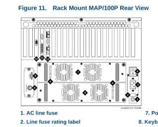
Getting Inside the Computer Removing Power from the MAP/100PFigure 11. Rack Mount MAP/100P Rear View
6
scinp006 KLC 032398
KE YB O A R D AYC54 Lucent CO M M 2 7 8 9 10 4 1 3 2 5 5 PO W E R O K (G R EEN ) PO W E R F AU LT (R ED ) PO W E R O K (G R EEN ) PO W E R F AU LT (R ED ) 11 12
1. AC line fuse
2. Line fuse rating label
3. AC power inlet receptacle
4. ON/OFF power switch with protective guard
5. Power supply status LED
6. Power supply 1
7. Power supply 2
8. Keyboard connector
9. COM2 port
10.Video circuit card (PCI slot 1)
11.P5 200 MHz CPU with COM1 and parallel port (slot 17)
1
Getting Inside the Computer Removing Power from the MAP/100PTo remove power from the MAP/100P, do the following:
1 Shut down the voice system. See “Administer the Voice System,” in “Common System Procedures,” in the Intuity CONVERSANT System Reference, 585-313-205.
2 Shut down the Intuity CONVERSANT system. See “Shut Down the System,” in “Common System Procedures,” in the Intuity CONVERSANT System Reference, 585-313-205.
3 Turn off the monitor’s power switch.
The green or amber lamp on the front bottom of the monitor should be off. 4 Turn off the power switch on the lower back of the MAP/100P (Figure 10
on page 6 and Figure 11 on page 7).
5 Unplug the MAP/100P from the power outlet.
6 Remove the MAP/100P power cord from the AC power input receptacle on the rear of the MAP/100P
(Figure 10 on page 6 and Figure 11 on page 7).
1
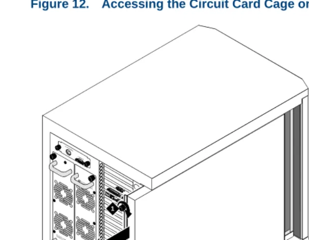
Getting Inside the Computer Accessing the Circuit Card CageAccessing the Circuit Card Cage
A dress cover provides protection for the internal components of the
MAP/100P. You must remove the side dress cover to access the circuit card cage.
!
CAUTION:
Shut power off before removing the dress cover. See Removing Power from the MAP/100P for the procedure.
To remove the circuit card cage dress cover, do the following:
Note: It may be helpful to place a deskside MAP/100P on its right side, resting it against a thick book or two.
1 Loosen the three thumb screws in the back of the unit (Figure 12 on page 10).
Note: These are captive screws.
1
Getting Inside the Computer Accessing the Circuit Card CageFigure 12. Accessing the Circuit Card Cage on a Deskside MAP/100P
scinpanl KLC 011198 1
1
1
1
Getting Inside the Computer Replacing the Dress CoverReplacing the Dress Cover
To replace the side dress cover, do the following: 1 Align the dress cover with the MAP/100P chassis. 2 Slide the dress cover until it locks into place.
Note: Make sure the tab on the front of the dress cover slides under the lip of the chassis.
3 Tighten the thumb screws on the back of the MAP/100P.
Restoring Power to the MAP/100P
To restore power to the MAP/100P, do the following:
1 Place the MAP/100P power cord in the AC input receptacle on the rear of the unit (Figure 10 on page 6 and Figure 11 on page 7).
1
Getting Inside the Computer Restoring Power to the MAP/100P4 Turn on the monitor’s power switch.
2
Installing or Replacing Circuit
Cards
Overview
The purpose of this chapter is to ensure that circuit cards are installed correctly and resource options are set correctly.
This chapter describes:
• Configuring circuit cards in the MAP/100P • Types of circuit cards
• General steps for circuit card installation
• Specific procedures for installation of standard and optional MAP/100P circuit cards
2
Installing or Replacing Circuit Cards General ProceduresGeneral Procedures
The general procedures include: • Removing a circuit card • Installing a circuit card
Removing a Circuit Card
!
CAUTION:
Observe proper electrostatic discharge precautions when you handle computer components. Wear an antistatic wrist strap that touches your bare skin and connect the strap cable to an earth ground. See Protecting against Damage from Electrostatic Discharge on page 2, in Chapter 1, Getting Inside the Computer for detailed electrostatic discharge precautions.
To remove a circuit card, do the following.
2
Installing or Replacing Circuit Cards General Procedures2 If the system is in service, do the following.
a Stop the voice system. See “Administer the Voice System,” in
“Common System Procedures,” in the Intuity CONVERSANT System Reference, 585-313-205.
b Shut down the voice system. See “Administer the Voice System,” in “Common System Procedures,” in the Intuity CONVERSANT System Reference, 585-313-205.
c Shut down the Intuity CONVERSANT system. See “Shut Down the System,” in “Common System Procedures,” in the Intuity
CONVERSANT System Reference, 585-313-205.
3 Remove power from the MAP/100P. See Removing Power from the MAP/100P on page 5 in Chapter 1, Getting Inside the Computer for power removal procedures.
4 Remove the dress cover. See Accessing the Circuit Card Cage on page 9 in Chapter 1, Getting Inside the Computer for component removal procedures.
2
Installing or Replacing Circuit Cards General Procedures8 Remove the circuit card from the backplane slot by gently pulling at the top corners of the circuit card.
Note: The backplane connector slots are labeled 1 through 20. Make sure to install the replacement card in the same backplane slot. 9 Remove the circuit card from the MAP/100P chassis.
!
CAUTION:
Hold the circuit card carefully by the edges and place it on a grounded mat. See Protecting against Damage from Electrostatic Discharge on page 2 in Chapter 1, Getting Inside the Computer for detailed electrostatic discharge precautions.
Installing a Circuit Card
!
CAUTION:
2
Installing or Replacing Circuit Cards General ProceduresNote: Keep the package and all ESD protective wrapping. If you must return a card for repair, reusing the replacement unit packaging is necessary to meet the manufacturer’s warranty. Be sure to include a description of the failure.
2 Verify the circuit card switch and jumper settings. Ensure address switches and jumpers are set to match the old card.
Note: See the specific instructions, listed later in this chapter, for each type of circuit card being installed then continue with Step 3. 3 Holding the circuit card by its upper corners, slide the card into the
backplane connector slot position from which you removed the damaged card.
4 Apply even pressure to both corners of the circuit card until it is locked into the backplane.
5 Secure the circuit card faceplate into position by replacing the retaining screw.
2
Installing or Replacing Circuit Cards Settings for Optional Circuit Cards9 Apply power to the unit. See Restoring Power to the MAP/100P on page 11, in Chapter 1, Getting Inside the Computer for instructions on restoring power.
10 Reboot the Intuity CONVERSANT system. See “Reboot the System,” in “Common System Procedures,” in the Intuity CONVERSANT System Reference, 585-313-205.
Settings for Optional Circuit Cards
!
CAUTION:
Observe proper electrostatic discharge precautions when you handle computer components. Wear an antistatic wrist strap that touches your bare skin and connect the strap cable to an earth ground. See Protecting against Damage from Electrostatic Discharge on page 2, in Chapter 1, Getting Inside the Computer for detailed electrostatic discharge precautions.
This section provides the following information on the optional feature circuit cards:
2
Installing or Replacing Circuit Cards Settings for Optional Circuit CardsIn general, circuit cards are not preset at the factory. You must set the switches and jumpers (resource options) before you install the cards. When you set the switches according to the instructions in this book, remember that OFF is equivalent to open and ON is equivalent to closed.
Tip/Ring Circuit Cards
The Tip/Ring circuit cards provide the channels which are used by the Intuity CONVERSANT system. The MAP/100P accommodates eleven Tip/Ring circuit cards. The Tip/Ring circuit card can be any of the following types: • IVP6-IA (AYC29)
• IVC6 (AYC10) • NGTR (AYC30)
The following section covers the resource option settings for each type of T/R card. Many of the figures referenced illustrate settings for more than one type of T/R card.
2
Installing or Replacing Circuit Cards Settings for Optional Circuit CardsIn general, you should leave all switches on Switch Bank A in the factory default “OPEN” position. If the system shows problems such as not
recognizing touch tones, touch-tone simulation by outgoing speech (speech abruptly stops during playback), or unreliable detection of touch tones during playback (playback does not stop when a touch tone is entered), moving the switch that corresponds to the channel exhibiting the conditions to the “CLOSED” position may solve the problem.
2
Installing or Replacing Circuit Cards Settings for Optional Circuit CardsFigure 13. Settings for Switches on the IVP6-IA (AYC29), and IVC6 (AYC10) Tip/Ring Circuit Cards T/R-0 through T/R-7
Base I/O address = 100 Hex.
IVC6-IU T/R 0 First card installed
Base I/O address = 200 Hex.
IVC6-IU T/R 1 Second card installed
Base I/O address = 300 Hex.
IVC6-IU T/R 2 Third card installed Base I/O address = 500 Hex.
IVC6-IU T/R 3 Fourth card installed
Base I/O address = 600 Hex.
IVC6-IU T/R 4 Fifth card installed
Base I/O address = 700 Hex.
Base I/O address = b00 Hex. IVC6-IU T/R 5 Sixth card installed
IVC6-IU T/R 8 Ninth card installed Base I/O address = 900 Hex.
IVC6-IU T/R 6 Seventh card installed
Base I/O address = a00 Hex.
2
Installing or Replacing Circuit Cards Settings for Optional Circuit CardsIVP6-IA (AYC29) Circuit Card
The IVP6-IA (AYC29) circuit card (Figure 14 on page 22) provides six channels. This circuit card contains switches that you must set before you install the circuit card in the MAP/100P.
Each Tip/Ring card in the system must have a unique address. To set these addresses, the switches must be configured properly. Figure 13 on page 21 shows the switch settings for the IVP6-IA (AYC29) circuit card.
Figure 14. Layout of the IVP6 (AYC29) Tip/Ring Circuit Card
Modular TDM bus
2
Installing or Replacing Circuit Cards Settings for Optional Circuit CardsIVC6 (AYC10) Circuit Card
The IVC6 (AYC10) circuit card (Figure 15 on page 23) provides six channels. This circuit card contains switches that you must set before you install the circuit card in the MAP/100P.
Figure 15. IVC6 (AYC10) Tip/Ring Circuit Card
8-pin modular jacks
Audio input TDM bus
terminator SIPs Rocker
2
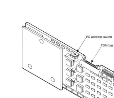
Installing or Replacing Circuit Cards Settings for Optional Circuit CardsNGTR (AYC30) Circuit Card
The NGTR (AYC30) circuit card (Figure 16 on page 24) provides six channels. This circuit card contains switches that you must set before you install the circuit card in the MAP/100P.
Figure 16. NGTR (AYC30)
I/O address switch
TDM bus B
TDM bus A TDM bus terminator SIPs
8-pin modular jacks
2
Installing or Replacing Circuit Cards Settings for Optional Circuit Cards2
Installing or Replacing Circuit Cards Settings for Optional Circuit CardsInstalling the Tip/Ring Circuit Card Driver
Note: If the Tip/Ring circuit cards are not recognized when the voice system is started or if other problems are noticed with the Tip/Ring circuit card driver, it may be necessary to remove and reinstall the Tip/Ring circuit card driver.
Occasionally dynamically loadable drivers fail to load into the UnixWare kernel properly.
To install the Tip/Ring circuit card driver, do the following:
1 Stop the voice system. See “Administer the Voice System,” in “Common System Procedures,” in the Intuity CONVERSANT System Reference, 585-313-205.
2 Run the Hardware Resource Allocator to determine the configuration and placement of the Tip/Ring circuit cards to be installed. See Adding Hardware to an Existing Configuration on page 517 in Appendix A, System Configuration.
3 If you are not already logged in as root, do so now. 4 Enter pkgadd -d diskette1
2
Installing or Replacing Circuit Cards Settings for Optional Circuit Cards5 Insert the diskette labeled “Tip/Ring Board Driver 1 of 1” into the diskette drive.
6 Press E N T E R.
The system displays the following message:
Installation in progress -- do not remove the diskette. The following packages are available:
1. tipring INTUITY Tip/Ring Board Driver (i486)
Select package(s) you wish to process (or ‘all’ to process all packages). (default: all) [?,??,q]:
7 Press E N T E R.
The system displays the following message:
PROCESSING:
Set: INTUITY Tip/Ring Board Driver (tipring) from <diskette1>
2
Installing or Replacing Circuit Cards Settings for Optional Circuit CardsThe system displays several status messages and then the following message:
Please enter the IRQ:
8 Enter the IRQ provided by the Hardware Resource Allocator.
The system displays several status messages and then the following message:
Installation of INTUITY Tip/Ring Board Driver (tipring) was successful.
Insert diskette into Floppy Drive 1. Type [go] when ready,
or [q] to quit: (default: go)
9 Enter q
10 Remove the diskette labeled “Tip/Ring Board Driver 1 of 1” from the diskette drive.
E1/T1 Circuit Card
2
Installing or Replacing Circuit Cards Settings for Optional Circuit CardsFigure 18. E1/T1 (AYC21) Circuit Card
TDM bus B (reserved for future use)
TDM bus A Bus B terminating resistors Bus A terminating resistors LED 8-pin modular jack TX connector (signal out) RX connector (signal in) SW1 (device number) SW2 (operating mode) Test port (lab use only)
J8 (shield ground) J7
2
Installing or Replacing Circuit Cards Settings for Optional Circuit CardsFigure 19. AYC21 Jumper Settings
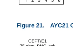
Switch Settings There are two sets of switches on the E1/T1 circuit card. Figure 20 on page 31 through Figure 22 on page 32 show the correct switch settings.
68302
J12 (IRQ select) J8
Ground RX outer conductor
Ground TX outer conductor
2
Installing or Replacing Circuit Cards Settings for Optional Circuit CardsFigure 20. AYC21 Device Number Switch 1 Settings
Figure 21. AYC21 Operating Mode Switch Settings for E1 Operation
CEPT/E1 75 ohm, BNC jack
2
Installing or Replacing Circuit Cards Settings for Optional Circuit CardsFigure 22. AYC21 Operating Mode Switch Settings for T1 Operation
Installing the E1/T1 Circuit Card Driver
Note: If the E1/T1 circuit cards are not recognized when the voice system is started or if other problems are noticed with the E1/T1 circuit card driver, it may be necessary to remove and reinstall the E1/T1 circuit card driver.
Occasionally dynamically loadable drivers fail to load into the UnixWare kernel properly.
2
Installing or Replacing Circuit Cards Settings for Optional Circuit Cards3 Enter pkgadd -d diskette1
The system displays the following message:
Insert diskette into Floppy Drive 1. Type [go] when ready,
or [q] to quit: (default: go)
4 Insert the diskette labeled “T1/E1 Board Driver 1 of 3” into the diskette drive.
5 Press E N T E R.
The system displays the following message:
Installation in progress -- do not remove the diskette. The following packages are available:
1. t1driver INTUITY T1/E1 Board Driver (i486)
Select package(s) you wish to process (or ‘all’ to process all packages). (default: all) [?,??,q]:
2
Installing or Replacing Circuit Cards Settings for Optional Circuit CardsUsing </> as the package base directory. Lucent Technologies Inc.
The system displays several status messages and then the following message:
READY TO PROCESS:
Package: Intuity T1/E1 Board Driver (t1driver) diskette 2 of 3
Insert diskette 2 of 3 into Floppy Drive 1. Type [go] when ready,
or [q] to quit: (default: go)
7 Remove the diskette labeled “T1/E1 Board Driver 1 of 3” from the diskette drive.
8 Insert the diskette labeled “T1/E1 Board Driver 2 of 3” into the diskette drive.
9 Press E N T E R.
The system displays several status messages and then the following message:
2
Installing or Replacing Circuit Cards Settings for Optional Circuit CardsInsert diskette 3 of 3 into Floppy Drive 1. Type [go] when ready,
or [q] to quit: (default: go)
10 Remove the diskette labeled “T1/E1 Board Driver 2 of 3” from the diskette drive.
11 Insert the diskette labeled “T1/E1 Board Driver 3 of 3” into the diskette drive.
12 Press E N T E R.
The system displays several status messages and then the following message:
Installation of T1/E1 Board Driver (t1driver) was successful.
Insert diskette into Floppy Drive 1. Type [go] when ready,
or [q] to quit: (default: go)
2
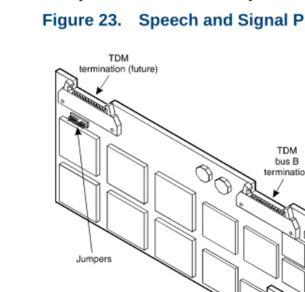
Installing or Replacing Circuit Cards Settings for Optional Circuit CardsSpeech and Signal Processor (AYC43) Circuit Card
The SSP circuit card (Figure 23 on page 36) contains switches and jumpers that you must set before you install the circuit card in the MAP/100P.
2
Installing or Replacing Circuit Cards Settings for Optional Circuit CardsJumper Settings Figure 23 on page 36 shows the location of the SSP circuit card jumpers. There should be no jumpers installed on the SSP circuit card.
Switch Settings There are two types of switches on the SSP circuit card: • Two-position switches
• Rotary switch
Two-Position Switch Settings
Figure 24 on page 37 shows the location of the SSP circuit card two-position switches. If the SSP circuit card is not located at the end of the TDM bus, both switches should be set to open. The switches should be set to closed if the SSP circuit card is located at the end of the bus.
Note: The switch in Figure 24 on page 37 is set for a placement in the middle of the TDM bus.
2
Installing or Replacing Circuit Cards Settings for Optional Circuit CardsRotary Switch Settings
Figure 25 on page 38 shows the rotary switch. It is set at zero for the first SSP circuit card installed in the MAP/100P.
Figure 25. SSP Circuit Card Rotary Switch
Table 1 on page 38 shows the rotary switch settings for the subsequent SSP circuit cards installed.
Table 1. SSP Circuit Card Rotary Switch Setting
I/O Address OS Index Rotary Switch Setting
d20 8 0
2
Installing or Replacing Circuit Cards Settings for Optional Circuit CardsMemory The SSP circuit card is equipped with 16 Mbytes of memory contained on a dual in-line memory module (DIMM). The DIMM is located in the lower portion of the SSP circuit card (Figure 23 on page 36).
!
CAUTION:
The DIMM is not field serviceable.
Installing the ASP
Driver Package To install the ASP circuit card driver, do the following:
920 12 4
928 13 5
930 14 6
938 15 7
Table 1. SSP Circuit Card Rotary Switch Setting
I/O Address OS Index Rotary Switch Setting
2
Installing or Replacing Circuit Cards Settings for Optional Circuit CardsThe system displays the following message:
Insert diskette into Floppy Drive 1. Type [go] when ready,
or [q] to quit: (default: go)
3 Insert the diskette labeled “ASP Driver Package 1 of 2” into the diskette drive.
4 Press E N T E R.
The system displays the following message:
Installation in progress -- do not remove the diskette. The following packages are available:
1. asp INTUITY ASP Driver Package (i486) cs3.1
Select package(s) you wish to process (or ‘all’ to process all packages). (default: all) [?,??,q]:
5 Press E N T E R.
The system displays the following message:
2
Installing or Replacing Circuit Cards Settings for Optional Circuit CardsNote: If you did not stop the voice system, the system displays the following message at this point:
The voice system is currently running and must be stopped in order to install this package.
Is it ok to STOP the voice system ? [y/n]
Enter y
The system displays the following message:
READY TO PROCESS:
Package: INTUITY ASP Driver Package (asp) diskette 2 of 2
Insert diskette 2 of 2 into Floppy Drive 1. Type [go] when ready,
or [q] to quit: (default: go)
2
Installing or Replacing Circuit Cards Settings for Optional Circuit CardsThe system displays several status messages and then the following message:
The UNIX Operating System kernel will be rebuilt to include your configuration changes during the next system reboot. Installation of INTUITY ASP Driver Package (asp) was successful.
Insert diskette into Floppy Drive 1. Type [go] when ready,
or [q] to quit: (default: go)
9 Enter q
10 Make sure the light on the diskette drive is off, and remove the diskette from the drive.
Reboot the system. See “Reboot the System,” in “Common System Procedures,” in Intuity CONVERSANT System Reference, 585-313-205.
PCI Ethernet LAN Circuit Cards
2
Installing or Replacing Circuit Cards Settings for Optional Circuit Cards2
Installing or Replacing Circuit Cards Settings for Optional Circuit CardsSMC9332 Circuit Card
The SMC9332 Ethernet LAN circuit card (Figure 27 on page 44) is a 10/100 Mbps circuit card. There are no jumpers on the circuit card.
2
Installing or Replacing Circuit Cards Settings for Optional Circuit CardsInstalling a PCI LAN Circuit Card
Installation of a 10 Mbps or a 10/100 Mbps PCI LAN circuit card, in a system which did not previously have a LAN circuit card, involves
~ Installing the PCI LAN Circuit Card on page 45
~ CMOS Parameter Settings on page 86
~ Installing the PCI Circuit Card Driver on page 47
~ Verifying the PCI LAN Circuit Card Installation on page 51
Installing the PCI LAN Circuit Card
To install either a 10 Mbps or a 10/100 Mbps PCI LAN circuit card, do the following:
1 Shut down the system if it is up and running, otherwise continue with step 2. See “Shut Down the System,” in “Common System Procedures,” in the Intuity CONVERSANT System Reference, 585-313-205.
2 Install the 10 Mbps or 10/100 Mbps PCI LAN circuit card. See Installing a Circuit Card on page 16 .
2
Installing or Replacing Circuit Cards Settings for Optional Circuit CardsInstalling a 100 Mbps PCI LAN Circuit Card
Note: Perform the following procedure if the SMC9332 circuit card is required to operate at 100 Mbps. If the SMC9332 circuit card is to operate at 10 Mbps, continue with Installing the PCI Circuit Card Driver on page 47 because no changes are required for 10 Mbps operation.
To ensure the SMC9332 circuit card operates at 100 Mbps, do the following: 1 Login as root.
2 Enter vi /etc/inst/nics/drivers/smpw0 3 Change the line SMPMEDIA0 SMC_MEDIA_AMD
to
SMPMEDIA0 SMC_MEDIA_STP100_UTP100
Note: SMPMEDIA0 is used for the first PCI LAN circuit card. If you system is using more than one PCI LAN circuit card, change SMPMEDIA1 (for card 2), SMPMEDIA2 (for card 3), or
SMPMEDIA3 (for card 4) as required, to read the same as that entered for SMPMEDIA0.
2
Installing or Replacing Circuit Cards Settings for Optional Circuit CardsInstalling the PCI Circuit Card Driver
To install the PCI LAN circuit card driver, do the following: 1 From the network administrator, determine the following:
~ The machine IP address ~ The machine node name ~ The system name
2 If you are not already logged in as root, do so now. 3 Enter niccfg
The system displays the following message:
Setting up the Network Interface Card Support Utility
2
Installing or Replacing Circuit Cards Settings for Optional Circuit CardsFigure 28. Network Interface Card Support Utility—Summary Screen
4 Use the down arrow to select: Accept all Entries
Note: If installing from a diskette, select:
Install Driver from IHV Diskette
SLOT BUS-NUM BOARD NAME IRQ IO-ADDR MAN-ADDDR DMA --- --- --- --- --- 6 PCI_0 SMC_EtherPower_9332 IO f880-f8ff fedfec00-fedfec7f
Please Select an Option
(*) Accept all Entries ( ) Add an entry for a card
( ) Delete/restore an Entry for a Card ( ) Install Driver from IH