MECHANICAL DESIGN OF A SODIUM COOLED FAST REACTOR
FUEL ASSEMBLY IN KOREA
Hyung-Kyu Kim1, Kyung-Ho Yoon1, Young-Ho Lee1, Hyun-Seung Lee2, and Jin-Sik Cheon3
1 Principal Researcher, LWR Fuel Technology Division, Korea Atomic Energy Research Institute, Korea 2 Senior Researcher, Next Generation Fuel Development Division, Korea Atomic Energy Research Institute, Korea
3 Principal Researcher, Next Generation Fuel Development Division, Korea Atomic Energy Research Institute, Korea
ABSTRACT
The mechanical design of the fuel assembly of a sodium cooled fast reactor (SFR) is presented in this paper. This is one of the design works of a Prototype Generation IV SFR (PGSFR), which is planned to be built in Korea. Among the design tasks of the fuel assembly, the normal operation conditions and brittle fracture are focused on here. The most difficult problem is attributed to the lack of an applicable design code because the currently available codes do not incorporate the material (HT-9) of the fuel assembly’s structural components. On this matter, the formulae of the yield and ultimate strengths of HT-9 are used here, which have been verified through a comparison with existing data in different references other than the codes. From this, we set up a conservative design criteria and stress limits. Two fuel assemblies of different locations in the reactor core are chosen for the analysis. Finite element analysis results show that the stresses are far below the stress limits. It was also found that the crack size that can cause a brittle fracture during fuel assembly handling is large enough to be detected using a normal non-destructive test. Thus, it is soundly concluded that the presently designed fuel assembly has sufficient structural integrity during normal operation and refuelling outage.
INTRODUCTION
A pressurized water reactor (PWR) is a major source of nuclear energy in Korea, which uses the once-through cycle of a nuclear fuel. However, a closed nuclear fuel cycle was recently planned in Korea using an SFR to reduce the spent fuel and enhance the usage of uranium resources. The nuclear steam supply system, fuels, and balance of the plant are under design to construct a prototype plant of an SFR (PGSFR) in Korea by 2028. When this project is successfully finished, it is expected that the supply of electricity will be more stable in Korea and that high-level nuclear wastes be considerably reduced.
mechanical design of the fuel assemblies. Further, the temperature range is very wide (~ 400-800ºC) in the PGSFR system depending on the service levels (normal operation and accident conditions), and it is compulsory to assess the structural integrity at each service level.
Another crucial issue is the design criteria. The ASME (Section III) (2013) and RCC-MRx (2012) codes are readily accessible to apply for the design criteria of the high-temperature nuclear reactor components. However, they cannot be applied to the PGSFR fuel assembly design because the material of the structural components (i.e., ferriticmartensitic steel) is not covered in them. Other criteria in the reports by Briggs et al. (1995) and Puthiyavinayagam (2009) tentatively developed for the SFR may be an alternative; however, all the service levels are not covered in them. This implies that the design criteria for the PGSFR fuel assembly need to be specifically developed. It has to include the generation of the mechanical properties as a function of temperature, although their validation is not easy owing to the insufficient material data. A brief comparison of all design criteria is reviewed in this paper.
Reflecting on them, this paper introduces the current results of the mechanical design of the PGSFR fuel assembly carried out at the Korea Atomic Energy Research Institute (KAERI). The general features of the fuel assembly are introduced first. The developed mechanical design criteria are then presented, which are used for the assessment of the structural integrity of a fuel assembly for the cases of normal operation. In addition, fracture mechanical analysis results are provided based on the concern of a brittle fracture during a fuel reloading outage.
FEATURE OF PGSFR FUEL ASSEMBLY AND COMPONENTS
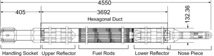
The length of a PGSFR fuel assembly is similar to that of a PWR fuel assembly (~ 4.5 m), but it has a hexagonal cross section of a smaller size (~ 135 mm, face to face). It is composed of a nose piece, a hexagonal duct, lower and upper shields, a handling socket, mounting rails (those are called ‘structural components’), and fuel rods. Fuel rods are surrounded by a long hexagonal duct of 3 mm in thickness, which is connected with a top handling socket and a bottom nose piece by welding. Therefore, there is no cross flow of a sodium coolant between the fuel assemblies owing to the tube-like duct. The upper and lower reflectors are installed inside the duct to reflect the fast neutrons emitted from the fissile material in the fuel rods.
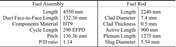
Overall, the fuel assembly looks like a pencil. It is a cantilever structure; the nose piece is clamped to the receptacle, which is again clamped to the robust plate in the reactor core; however on the other side the handling socket is free without any clamping. There are protruding parts in the middle of the duct (above core load pad; ACLP) and top of the handling socket (top load pad; TLP) to allow a mechanical contact with the adjacent fuel assemblies without causing damage of the overall structure during handling and irradiation. All structural components are made of HT-9, ferriticmartensitic steel, to minimize the irradiation swelling and thermal creep. Figure 1 shows a schematic drawing of the PGSFR fuel assembly. A fuel rod is composed of a wire-wrapped cladding tube of FC92 in which a U-10Zr fuel slug with a Na bonding material is installed. The cladding material, FC92, developed at KAERI, was improved from HT-9. A schematic drawing of the fuel rod is provided in Figure 2. Some of the key design parameters of the PGSFR fuel assembly are provided in Table 1.
Figure 2. Schematic drawing of a PGSFR fuel rod.
Table 1: Design parameters of the PGSFR fuel assembly and rod.
Fuel Assembly Fuel Rod
Length Duct Face-to-Face Length Components Material Cycle Length Pitch P/D ratio
4550 mm 132.36 mm HT9 290 EFPD 136.36 mm 1.14
Length Clad Diameter Clad Thickness Active Length Plenum Length Slug Diameter
2240 mm 7.4 mm 0.5 mm 900 mm 1275 mm 5.54 mm
DESIGN CRITERIA AND STRESS LIMITS
We attempted to apply the design method and criteria of the ASME Section III Division 5 (2013) at first because it was developed for a high-temperature reactor and its components. However, there are three critical problems in using the ASME code. First, it does not provide the material properties of HT-9, which should be used to evaluate the stress intensities of the criteria, such as Sm and St, the time-independent and dependent (i.e., creep related) parameters, respectively. The difficulty in determining Sm may be resolved by using the formulae of the yield and ultimate strengths obtained from elsewhere. However, as a second problem, St is much harder to be determined even though the formulae of creep behaviour are used owing to some ambiguities in the definitions of St. This is attributed to the creep formulae, which we can use for HT-9 (Briggs et al., 1995), which consist of each independent creep stage (i.e., primary, secondary and tertiary) and fitted using long-term experimental data. Thus, a definition such as ‘a minimum stress that initiates the tertiary creep’, i.e. the third definition of St in the ASME code (2013), does not give a correct value of St if it is determined from the formulae. In addition, the ASME code does not deal with the irradiation, which is another critical problem for the present purpose.
The RCC-MRx code may be an alternative, which has also been developed for the design of the high-temperature reactor components. A stronger point, compared with the ASME code, is that it incorporates the irradiation effect. Nevertheless, the same problem is incurred in the RCC-MRx code, that is, the HT-9 data are not covered there either. Moreover, the categorization of the stress limits is different from that of the ASME code. Eventually, it was concluded that the ASME and RCC-MRx codes cannot be used for the mechanical design of the PGSFR fuel assembly structural components.
designated as Pm, Pb, and Q in order. Eventually, the structural integrity can be assured when Pm, (Pm+Pb) and (Pm+Pb+Q) are less than each stress limit at each level.
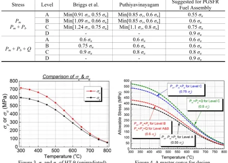
Table 2 summarizes the stress limits in each reference and finally determined for the PGSFR fuel assembly design. It should be noted that only the ultimate strength is used for the PGSFR fuel assembly stress limits. This is attributed to the magnitude of the yield and ultimate strengths (designated as σy and σu, respectively) of HT-9 when they are multiplied by specified safety factors for each service level. Level A is for the normal operation and refuelling. The probability of the accident reduces tremendously (say, by 10-2) as the level changes from B through D. We used the relevant formulae of σy and σu of HT-9 under non-irradiated conditions (Kim, 2015). The unirradiated condition is considered for conservatism because σy and σu increase when irradiated. The result is given in Figure 3. The calculated HT-9 data were verified through a comparison with the experimental data provided in the report by Briggs et al. (1995).
On the other hand, it should be noted that the Level D criterion is set as 0.9 σu regardless of Pm, (Pm+Pb) and (Pm+Pb+Q) in Table 1. This was determined without a particular reason. Relevant limits were not provided by Briggs et al. (1995) or Puthiyavinayagam (2009). Because the material cannot withstand the ultimate strength in any case, it was determined so by accommodating some allowance (i.e., 10%). In fact, however, it would not be used in the actual design evaluation for conservatism. This implies that the evaluated stresses in the case of Level D will be necessarily compared with the limits of the lower levels. As a result, we prepared a master curve of the stress limits for each level, as given in Figure 4.
Table 2. Comparison of the stress limits of references (Briggs et al., 1995 and Puthiyavinayagam, 2009), and the PGSFR fuel assembly structural components.
Stress Level Briggs et al. Puthiyavinayagam Suggested for PGSFR Fuel Assembly
Pm
Pm + Pb
A Min[0.91 σy, 0.55 σu] Min[0.85 σy, 0.6 σu] 0.55 σu B Min[1.09 σy, 0.66 σu] Min[0.85 σy, 0.6 σu] 0.6 σu C Min[1.24 σy, 0.75 σu] Min[1.1 σy, 0.8 σu] 0.75 σu
D - - 0.9 σu
Pm + Pb + Q
A 0.6 σu 0.6 σu 0.6 σu
B 0.75 σu 0.6 σu 0.6 σu
C 0.9 σu 0.8 σu 0.8 σu
D - - 0.9 σu
ANALYSIS FOR NORMAL OPERATION CONDITIONS
Preparation of Inputs
To select a representative fuel assembly for the present analysis, the temperature condition is of primary concern because the ultimate strength (and yield strength as well) of HT-9 decreases as the temperature increases. As a result, the fuel assembly of No. 1 (FA01), which is located at the center of the reactor core, the beginning of life (BOL) of Cycle 9 was chosen because it was subject to the highest temperature. However, the temperature difference between the duct faces of FA01 was comparatively small, so a bending stress could not be expected to occur in a meaningful way. Therefore, another fuel assembly was additionally chosen which showed the biggest difference in temperature between the duct faces. As a result, the fuel assembly of No. 84 (FA84), which is located at the fifth row in the reactor core, and at the BOL, Cycle 9, was additionally chosen.
In addition to the temperature difference, each fuel assembly is located in a different flow zone inside the reactor core. Thus, the pressure difference between the inside and outside the duct was also calculated for each fuel assembly. It is readily expected that the temperature increases whereas the pressure decreases as the elevation increases from the bottom of the fuel assembly owing to the location of the fuel rod bundle. Therefore, it is necessary to have the temperature and pressure data along the fuel assembly height to pick up the largest stress value. Consequently, the elevations where the temperature and pressure data were necessary for the analysis were determined, such as shown in Figure 5. Figure 6 shows the temperature data along the fuel assembly height, and the pressure data are given in Figure 7.
Figure 5. Elevations where the temperature and pressure data are prepared.
Figure 7. Pressure data of fuel assemblies No. 1 (FA01) and No. 84 (FA84).
Finite Element Analysis
A three-dimensional finite element model of a full-sized fuel assembly (excluding the components inside the duct such as the upper and lower reflectors, fuel rods, and mounting rails) was prepared. A commercial finite element analysis program, ABAQUS (2016) was used for modeling and analysis. The elements of an 8-node thermally coupled brick, trilinear displacement, and temperature (C3D8T) were used. The total numbers of elements and nodes were 37,376 and 48,153, respectively.
The applied boundary conditions were as follows. The bottom of the nose piece was restrained along the fuel assembly axis. A frictionless contact condition was given to the contact surface between the nose piece and receptacle so that a radial displacement could be prohibited. However, rotation was allowed for these locations. It was assumed that a gap exists between the adjacent fuel assemblies during normal operation.
As the analysis results show, it was found that the stresses were concentrated at the duct inner corners, as shown in Figure 8. Thus, the Von Mises stress was investigated at each corner, which is illustrated in Figure 9. The stresses except the region of the nose piece are shown, where those were negligible.
Overall, the stresses of FA01 are higher than those of FA84, and the stresses at the region of the ACLP abruptly drop owing to the increased thickness. FA84 shows a larger difference in stresses at each corner than FA01. This is because the temperature difference between the duct faces is larger in the case of FA84.
Figure 9. Von Mises stresses at each inner corner of the duct of FA01 and FA84. C1-C6 designates a corner location. For instance, C1 is the corner between face numbers 1 and 2.
Assessment Result
The stresses at each elevation were linearized to obtain Pm, Pb, and Q. The maximum values of Pm, (Pm+Pb) and (Pm+Pb+Q) at each elevation were then calculated and compared with the stress limits of Level A (see Table 2), i.e. 0.55 σu, which were obtained for the maximum temperature at each elevation. This means that the location of the maximum stress may not coincide with that of the maximum temperature at each elevation. This can provide an ultimate conservatism for the present analysis simultaneously when applying 0.55 σu as a stress limit for (Pm+Pb+Q) as well. In other words, 0.55 σu was conservatively used for the stress limit of (Pm+Pb+Q) although it is 0.6 σu according to Table 2.
Figure 10 illustrates the maximum values of Pm, (Pm+Pb), (Pm+Pb+Q), and 0.55 σu corresponding to the maximum temperature at each elevation of FA01 and FA84. The maximum (Pm+Pb+Q) of FA01 is 53 MPa and that of FA84 is 38 MPa. These are far below the stress limits, i.e. 369.5 MPa at 390ºC and 235 MPa at 558ºC. A sufficient margin is found between the data of 0.55 σu and evaluated stresses for both fuel assemblies. Therefore, it is soundly concluded that the structural integrity of the PGSFR fuel assembly components is guaranteed during normal operation from a strength standpoint.
BRITTLE FRACTURE CONCERN
Brittle Fracture of Duct
A brittle fracture is of particular concern when handling a fuel assembly in the reactor because the temperature will decrease to less than the ductile-to-brittle temperature (DBTT) of HT-9 (Chen, 2013). If there is a crack in the structural components (duct, especially) and a fuel assembly is stuck with adjacent fuel assemblies at the ACLP or with a receptacle at the piston ring, then a pulling of the fuel assembly during unloading from the reactor core can cause a failure of the components owing to the crack propagation. This concern should be resolved.
For the present analysis, it is supposed that a maximum pull-up force is applied to the fuel assembly, which is assumed as the maximum design load of the in-reactor transportation machine (IVTM). It is necessary to confine the crack size that can prevent the brittle fracture under this circumstance. When it is detected using a proper non-destructive examination technique, it should be controlled. This also means that the calculated allowable crack size should be sufficiently larger than the minimum detectable size of the techniques.
Linear elastic fracture mechanics is used to obtain the stress intensity factors of a crack of supposed geometry, i.e. shape, size and orientation. A mode I crack is of primary concern for the orientation, which is aligned perpendicular to the applied loading, and results in the most severe crack propagation. Thus, the mode I stress intensity factor, KI, is to be calculated first. The calculated KI should be less than the plane strain fracture toughness, KIC, which is obtained from a standard test or material data handbook. In short, the present criterion of the brittle fracture is written as follows.
KI < KIC (1)
For the PGSFR fuel assembly, KIC = 31 MPa·m1/2 (Chen, 2013) was used.
In this analysis, two different types of crack were assumed: a part-through crack of a semi-elliptical shape and a through crack. The formulae of KI of each crack type are as follows (Barsom and Rolfe, 1999): i) A part-through surface crack of a semi-elliptical shape (length measured on the surface being 2b and maximum depth into the thickness being a)
k
I Ya M
K =1.12σ π ⋅ (2)
where σis the far-field applied stress exerted to the crack tip. Y is a shape parameter that depends on σ/σy and the ratio of crack length viewed from the surface to the maximum depth, i.e. a/2b (Paris and Sih, 1965). For the present surface crack of a semi-elliptical shape, 1.0 ≤Y≤ 2.4 (because σ/σy < 0.1). Mk is expressed approximately as follows, which corresponds to a back free-surface correction factor.
⎟ ⎠ ⎞ ⎜ ⎝ ⎛ − +
=1.0 1.2 0.5 t a
Mk for a/t≥ 0.5 (3)
where t is the thickness of the plate. Mk ≈ 1.0 for a/t < 0.5. Thus, 1.0 ≤Mk ≤ 1.6.
As a result, the crack depth should be shallower than ac (critical crack depth), and expressed as follows.
2
12 .
1 ⎟⎟⎠
⎞ ⎜⎜ ⎝ ⎛ = k IC c M K Q a σ
π (4)
a
KI =σ π (5)
Therefore, the crack length should be shorter than ac (critical crack length), and expressed as follows.
2
1
⎟ ⎠ ⎞ ⎜ ⎝ ⎛ =
σ
π IC
c K
a (6)
First, the stresses produced in the structural components were calculated using a commercial finite element analysis program, ABAQUS (2016). A three-dimensional full-sized fuel assembly, except for the internal upper and lower reflectors, fuel rod bundle, and mounting rails, was modelled. Linear hexahedral elements (C3D8) were used. The total numbers of elements and nodes in this analysis were 282,608 and 418,077, respectively.
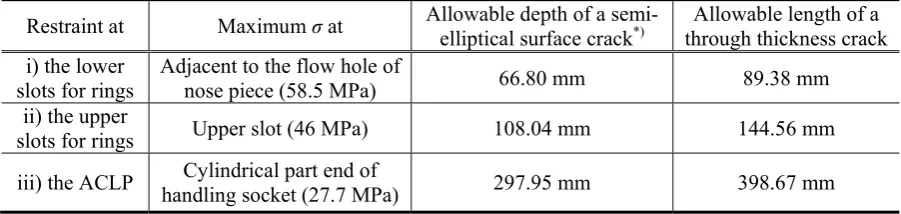
A maximum IVTM load of 26,689 N (≈ 27 kN) was applied to the side hole of the handling socket for the loading condition. Three restraint conditions were considered: restraint of the axial displacement i) at the lower slots for the rings, ii) at the upper slots for the rings, and iii) at the ACLP. KI was calculated for each condition. The stresses produced at each restraint condition are summarized in Table 3.
Table 3. Finite element analysis results of the stresses while exerting the maximum pulling load to the gripper hole of the handling socket
Restraint at Maximum stress (σ) Stress in duct (σ)
Location Value Location of max/value Average value i) the lower
slots for rings Adjacent to the flow hole of nose piece 58.5 MPa Boundary of ACLP/ 23.0 MPa 20.2 MPa ii) the upper
slots for rings Upper slot 46 MPa Boundary of ACLP/ 23.0 MPa 20.2 MPa iii) the ACLP Cylindrical part end of handling socket 27.7 MPa Boundary of ACLP/ 25.0 MPa 20.2 MPa
In turn, the values of σ in Table 3 were substituted into Eqs. (4) and (6) to obtain the allowable crack depth (or length). The results are summarized in Table 4.
Table 4. Allowable crack depth or length depending on the location of the crack and restraint conditions
Restraint at Maximumσ at Allowable depth of a
semi-elliptical surface crack*) through thickness crack Allowable length of a i) the lower
slots for rings
Adjacent to the flow hole of
nose piece (58.5 MPa) 66.80 mm 89.38 mm
ii) the upper
slots for rings Upper slot (46 MPa) 108.04 mm 144.56 mm
iii) the ACLP handling socket (27.7 MPa) Cylindrical part end of 297.95 mm 398.67 mm
If we recall the thicknesses of the nose piece (10 mm), duct (3 mm), and cylindrical part of the handling socket (5 mm), the allowable crack depths in Table 4 are much greater. In addition, the width of the duct flat (around 73 mm) is considerably shorter than the allowable crack length (749.67 mm). These results show that such cracks cannot be anticipated to actually exist. Therefore, in conclusion, a brittle fracture of the PGSFR fuel assembly components during handling can be prevented because the crack can be readily detected by an ordinary non-destructive test technique before it grows to cause a catastrophic failure.
CONCLUSION
The mechanical design of an SFR fuel assembly is carried out for the conditions of normal operation and fuel assembly handling (refuelling outage). To this end, new stress limits are established, which are composed of the ultimate strength of HT-9 and safety factors conservatively determined for each service level (Table 2). FA01 and FA84 (core centre and fifth row, respectively) were chosen for the analysis of normal operation condition. The maximum stresses (Pm+Pb+Q) of the assemblies are around 38 and 53 MPa (FA84 and 01, respectively), which are far below the stress limits (369.5 and 235 MPa at 390 and 558ºC, respectively). On the other hand, the allowable crack sizes are evaluated as 66-398 mm when the brittle fracture of a duct is of concern during fuel assembly handling. They are much larger than the detectable size of a normal non-destructive test technique, e.g. an ultrasonic test. Therefore, the structural integrity of the presently designed PGSFR fuel assembly is assured.
ACKNOWLEDGMENTS
This work was supported by the National Research Foundation (NRF) of Korea grant funded by Korea government (MSIP) (No.2012M2A8A2025646).
REFERENCES
ABAQUS ver. 2016
ASME Section III Division 5 (2013). Article HGB-3000, 123-138.
Barsom, J.M. and Rolfe, S.T. (1999). Fracture and Fatigue Control in Structures, 3rd ed., Butterworth-Heinemann, 35-39.
Briggs et al. (1995). Safety Analysis and Technical Basis for Establishing an Interim Burnup Limit for
Mark-V & Mark-VA Fueled Subassemblies in EBR-II, Argonne National Laboratory, USA.
Chen, Y. (2013). “Irradiation effects of T-9 Martensitic Steel,” Nuclear Engineering and Technology, Korea, 311-322.
Kim, J.-H. (2015). “Material models of metallic fuel,” SFR-170-FC-459-001, KAERI, (in Korean).
Paris, C.P and Sih, G.C. (1965). “Stress analysis of cracks, in Fracture toughness testing and its application,” ASTM STP 381, ASTM, Philadelphia.
Puthiyavinayagam, P. (2009). Joint ICTP/IAEA School on Physics and Technology of Fast Reactors
Systems: Module 4 Mechanical Design.
RCC-MRx (2012 Edition with 2013 1st Addendum) – SECTION III (Rules for Mechanical Components of
Nuclear Installation) – TOME 1 (Design and Construction Rules) – SUBSECTION B (Class NIRx