ISSN(Online): 2320-9801
ISSN (Print) : 2320-9798
I
nternational
J
ournal of
I
nnovative
R
esearch in
C
omputer
and
C
ommunication
E
ngineering
(An ISO 3297: 2007 Certified Organization)
Vol. 3, Issue 9, September 2015
Relay-Assisted Free Space Optical (FSO)
Communication with LDPC Coding and
Convolutional Coding
Alina Sunny1, K. Karunakaran Nair2, Sudhi.S3
M. Tech Student, Dept. of ECE, Amal Jyothi College of Engineering, Mahatma Gandhi University, Kottayam, Kerala,
India1
Professor, Dept. of ECE, Amal Jyothi College of Engineering, Mahatma Gandhi University, Kottayam, Kerala, India 2
Assistant Professor, Dept. of ECE, College of Engineering and Technology, Kerala University, Kottayam, Kerala,
India3
ABSTRACT: Over recent last decades free space optical communication (FSO) has become more interesting and it can be seen as an alternative to radio frequency communication. FSO is a very long technology to fix the optical radiation that pass through the atmosphere from one point to other. Atmospheric turbulence induced fading is one of the main disadvantage that affects the Free Space Optical communication. Relay assisted Free Space Optical communication employing ON-OFF Keying (OOK) is employed as modulation technique. FSO communication is done in LDPC coding and convolutional coding are being analysed. The performance results are evaluated in terms of bit error rate (BER). It is found that relay assisted LDPC coded Free Space Optical system with OOK modulation technique provides higher performance.
KEYWORDS: Free Space Optics (FSO); Low Density Parity Check (LDPC); Decode and Forward Relay.
I. INTRODUCTION
Free Space Optical Communication (FSO) is a technology that gives better transmission of information as optical radiation through the atmosphere from one point to another point and viceversa. Basically, FSO involves the transfer of data or information between two points using optical radiation as the carrier signal through unguided channels. Today’s FSO system use either lasers or LED to transmit a modulated beam of visible or infrared light. The data to be transported could be modulated on the intensity or frequency or phase of the optical carrier. For the exchange of information between the transmitter and receiver we are using Line Of Sight (LOS) technology where the transmitter and receiver can directly see one another without any block or disturbance in their path. The optical wave propagation through the air experiences fluctuations in amplitude and phase due to atmospheric turbulence.
FSO communication link have various advantages over conventional microwave and optical fiber communication system. The main feature of Free Space Optics technology is that it is having a huge bandwidth. In any communication system, the amount of data transported is directly proportional to the bandwidth of the modulated signal, and it can be up to 20 % of carrier frequency. By using an optical carrier where the frequency ranges from 10 to 10 Hz could allow data bandwidth up to 2000 THz. Therefore optical communication guarantees higher information capacity when compared to radio frequency based communication system.
ISSN(Online): 2320-9801
ISSN (Print) : 2320-9798
I
nternational
J
ournal of
I
nnovative
R
esearch in
C
omputer
and
C
ommunication
E
ngineering
(An ISO 3297: 2007 Certified Organization)
Vol. 3, Issue 9, September 2015
and several months of bureaucracy when slice of RF spectrum is allocated. In FSO, optical frequency are free from all this, which implies that initial setup cost is lower and deployment time is also shorter.
The fog, smoke, and turbulence have a great impact on FSO links performances. Absorption, scattering, and refraction of optical waves by gas molecules, smoke, rain and fog which leads to severe attenuation of optical intensity. Irradiance fluctuation of received optical signal due to the turbulence present a severe problem which mainly leads to the variation of refractive index. This may lead to severe system performance degradation. The effect of turbulence can be overcome by using MIMO systems and also selecting a modulation format that is also immune to scintillation is also important. OOK modulation scheme are widely used in commercial FSO system because of their ease of implementation, bandwidth efficiency and cost effectiveness.
II. RELATED WORK
Several techniques to reduce turbulence-induced intensity fluctuations [1] that is signal fading. These techniques are applicable in the system in which the receiver aperture is smaller than the correlation length of fading and the observation interval is shorter than the correlation time of fading. Here, the receiver has no knowledge of the instantaneous fading state and the receiver knows only the marginal statistics of the fading. A symbol-by-symbol ML detector can be used to improve detection performance. If the receiver has awareness of the joint temporal statistics of the fading, maximum likelihood sequence detection (MLSD) can be employed, which gives a better performance improvement, but at the cost of very high complexity. Spatial diversity reception with multiple receivers can also be used to overcome turbulence-induced fading. ML detection in spatial diversity reception is used to reduce the diversity gain penalty caused by correlation between the fading at different receivers. The [3] gives performance of the free space optics system by employing three different modulation techniques. The modulation techniques are On-Off Keying (OOK) with Non Return to Zero (NRZ) and Return to Zero (RZ) modulation and Binary Phase Shift Keying (BPSK) technique which operating under turbulent condition. Here the received signal is used to characterize the strength of turbulence in channel. The temperature gradient within controlled channel results in turbulence of log radiance variance of approximately 0.02, which is very weak turbulence. The analysis shows that performance of BPSK is better than OOK-NRZ and OOK-RZ at the expense of bandwidth and power efficiencies. A cooperative free space optical amplify and forward relay is considered to deal with the main challenges that are fading and path loss [4]. The photon counting method is used to find the system bit error probability performance and study of system performance with the effects of atmospheric turbulence, variations in background light, amplified spontaneous emission and system thermal noise and comparison of the system with multiple transmitter (MT) system can also be seen. The performance of relay assisted system is much better than MT systems. Analytical approach is done to evaluate the bit error performance of an LDPC coded Free Space Optical communication employing On-Off Keying (OOK [5], Binary Phase Shift Keying (BPSK), Q-ary Pulse Position Modulation (QPPM) as modulation technique. LDPC coded FSO communication system with QPPM provides significant coding gain over uncoded system when compared with other modulation techniques. This [2] paper present the concept of relaying to FSO. The fading variance is distance dependent in FSO systems which constitutes a major difference between RF (Radio Frequency) and wireless optical system. Multi-hop FSO transmission can achieve shorter distance in hops and brings improvements against the degrading effects of turbulence induced fading. Artificial broadcasting is obtained with the use of multiple transmitter apertures directed to relay nodes in parallel relaying.
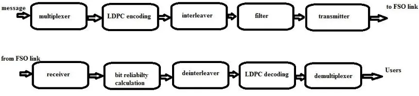
III.OVERVIEWOFEXISTINGSYSTEM
Free Space Optical communication system which is assisted by Decode and Forward (DF) relay is considered. Figure 1 shows relay assisted FSO communication link employing OOK modulation.
A. Source
ISSN(Online): 2320-9801
ISSN (Print) : 2320-9798
I
nternational
J
ournal of
I
nnovative
R
esearch in
C
omputer
and
C
ommunication
E
ngineering
(An ISO 3297: 2007 Certified Organization)
Vol. 3, Issue 9, September 2015
B. Modulator
The OOK modulation technique is used to modulate the input or source data into the electromagneticwave. In this part the data signal is modulated with carrier signal so that it canbe transmitted over the channel.
OOK modulation
To improve the BER performance of a FSO system that cause due to scintillation, selectionof appropriate modulation scheme is the main factor that determines the overall system performance. On-Off Keying is simple and commonly adopted modulation scheme. Inthis transmitted 1 is on and transmitted 0 is off. In RZ (Return to Zero) format, each opticalpulse representing bit 1 is shorter than bit slot, and its amplitude returns to zero before the bitduration is over. It is used for long distance transmission because of its higher peak power,high SNR ratio and lower bit error rate. RZ pulses always create distinct transition betweenencoded bits and hence create a clean optical signal to the receiver end to read. In NRZ(Non Return to Zero), the optical pulse remain on throughput the bit slot and its amplitudedoes not decreases to zero between two or more successive 1 bits. The main advantage ofNRZ-OOK is that the bandwidth required with the bit stream is smaller than RZ. In theOOK system, the data sequence is converted to electrical signal [7] by
( , ) =Σ ( − ) (1)
where is the signal level for the data symbol, is the symbol time and g(t) is theshaping pulse.
Figure 1: Block diagram of relay assisted FSO system
C. Transmitter and receiver
Transmitter modulates the data source into the optical carrier, which is then propagatesthrough atmosphere to the receiver. The most commonly used modulation is intensity modulation,where the source data is modulated into the irradiance of optical radiation. Thetransmitter mainly used is telescope that collects, focus into narrow beam and then directsthe optical radiation towards the receiver telescope at the other end of channel. The intensityof the transmitted beam [7] can be written as
( ) = 1 +Σ ( − ) (2)
ISSN(Online): 2320-9801
ISSN (Print) : 2320-9798
I
nternational
J
ournal of
I
nnovative
R
esearch in
C
omputer
and
C
ommunication
E
ngineering
(An ISO 3297: 2007 Certified Organization)
Vol. 3, Issue 9, September 2015
At the receiver, the received signal after the optical to electrical conversion, the source beam is projected towards the receiver using an expanding telescopeand the receiver is implemented based on P-I-N photo-detector. Optical band pass filter isused to reduce the amount of background radiation. The required amplification, filteringand signal processing is done by post detection processor which is necessary to guaranteethe carried out data must done high fidelity data recovery. Then the output of this beam istransmitted to users.
D. Atmospheric channel
Atmospheric turbulence mainly caused due to the random fluctuation of the atmosphericrefractive index along the path of optical field or radiation traversing the atmosphere. Therandom variations in atmospheric temperature from point to point is caused due to this refractiveindex fluctuation. Atmospheric turbulence mainly depends on i) atmospheric pressure oraltitude ii)wind speed iii)variation of index of refraction due to temperature inhomogeneity.In the area of wireless communication, the loss in signal strength when it propagates throughLine Of Sight(LOS) path in free space, with no obstacles nearby to cause reflection or diffraction is called Free Space Path Loss (FSPL) [10].
= (3)
where d is the distance between transmitter and receiver, λ is the wavelength (mostly usedwavelength is 1550nm).
E. Convolutional Coding
The information and codewords of convolutional codes are of infinite length, and thereforethey are mostly referred to as information and code sequence [9]. The encoding anddecoding is done by trellis and viterbi state diagrams
IV.PROPOSED SYSTEM
Consider a high-energy dual-hop optical wireless communication system using intensity modulationwith direct detection and On Off keying (OOK) modulation whose performance is limited by turbulence effect. Figure 1, shows the block diagram of Free Space Opticalcommunication system with OOK modulation. The encoder and decoder configurations aregiven in Figure 2. Like any other communication systems, FSO systems mainly comprisesof transmitter, channel and receiver. In addition to the basic parts, we are using Decodeand Forward (DF) relay in between the transmitter and receiver to mitigate the effects ofturbulence in channel.
Figure 2: FSO transmitter side and processor configuration(LDPC Coded
)
A. System Model
ISSN(Online): 2320-9801
ISSN (Print) : 2320-9798
I
nternational
J
ournal of
I
nnovative
R
esearch in
C
omputer
and
C
ommunication
E
ngineering
(An ISO 3297: 2007 Certified Organization)
Vol. 3, Issue 9, September 2015
component of LDPC code. The mxnblock interleaver, collects the m code words written in row wise. The mapper receives m bitsat a time from interleaver column wise and determines the corresponding slot for signaling. The total transmitted power is fixed and independent of number of lasers, therefore theemitted power is P/number of sources. This improves the tolerance to the turbulence that is affected in the system. At the receiver the received signal r(t) after the optical to electrical conversion [11] is defined as
( ) = ℎ( ) + ( ) (4)
where is the transmitted light intensity, h is the channel fading coefficient and n is the receiver noise. The source beam is projected towards the receiver using an expanding telescopeand the receiver is implemented based on P-I-N photo-detector.
B. Channel Model
The atmospheric free space optical channel is the medium for the outdoor optical wirelesscommunication. The free space optical channel has a wide bandwidth. The reliability of thecommunication link can be determined if we use good probabilistic model. The wavelength ofthe signal(q)is approximately 1.6 where visibility,v > 50km.
In an optical communicationsystem through the turbulent atmosphere, the intensity P(u,t) of the received signal [7] canbe written as
( , ) = ( , ) ( ) (5)
where A(u,t) is random process for the signal degradation due to atmospheric turbulence, u is an event in sample space and ( ) is received optical intensity in the absence of turbulence.
C. Delay and Forward Relay
In Decode and Forward Relaying, Figure 3 showsthe relay decodes the received signal and thenmodulates with optical power P, and if the received signal to noise ratio exceeds given decodingthreshold it will transmits to the final destination. This threshold is used to avoid theerror propagation. The total transmitted power, is related to average transmitted opticalpower per transmit aperture, P can be defined as P = /2. The channel gain [3] can beformulated by
= (6)
where α is the turbulence induced fading amplitude and L denotes the normalized path losswith respect to the path between the source and destination.
Figure 3: Block Diagram of Decode and Forward Relay
D. BER of the coded system
By OOK modulation, the output of the receiver in response, (OFF) and (ON), to symbolq are processed. When there is no turbulence only noise is present, the BER of the system[6] can be written as
= (7)
ISSN(Online): 2320-9801
ISSN (Print) : 2320-9798
I
nternational
J
ournal of
I
nnovative
R
esearch in
C
omputer
and
C
ommunication
E
ngineering
(An ISO 3297: 2007 Certified Organization)
Vol. 3, Issue 9, September 2015
( ) = : [ ( )]
: [ ( )](8)
E. Channel Coding
The performance of the noisy channel relates the Signal to Noise Ratio (SNR) of the receivedsignal to the Bit Error Rate (BER). An important issue is to use appropriate channel codingscheme when OOK modulation is used. There are a number of coding techniques which canbe used, like Reed Solomon codes, Turbo codes, which is proposed so far. The problem ofthese codes is their decoding complexity that can be prohibitively large for practical use inGbps rate transmission of a FSO system. The performance of the relay assisted system iscalculated with LDPC coding [8]. This provides a better performance than convolutionalcoding. It can achieve performance that is close to Shannon's limit, when the code wordlength is long. Its main advantage is that it is having lower decoding complexity than turbocodes, that is decoding can be at significantly greater speeds than decoding of turbo code.
V. SIMULATION RESULTS
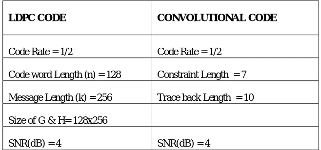
The graph of Bit Error Rate (BER) versus Signal to Noise Ratio (SNR) is used for theperformance analysis. Bit error rate (BER) of a communication system is defined as the ratioof number of error bits and total number of bits transmitted during a specific period. SNR isdefined as the ratio between signal power to noise power and it is normally expressed in decibel(dB). A powerful fading mitigate tool is relay assisted transmission through atmosphericturbulence. Turbulence induced fading variance depends upon propagation distance that a light source that will travel through FSOsystem. To overcome this situation, relay assisted transmission will be a great advantage of resulting shorter hops from the transmitter to the receiver, to improve the significant performance. The parameters that are used for computations are shown inbelow table 1.
Table 1:Simulation paramaters used for computation
Figure 4 shows the relation between Bit Error Rate and Signal to Noise Ratio with relayin the system by convolutional coding and LDPC coding. Since the data that propagates through the atmosphere is affected by the turbulence effects, and hence the data may be faded and sometimeslost.To overcome that situation, the use of relay, that re-encode the received signal at therelay system and retransmits to the receiver, the receiver then process the data to the users, where it can be used without a large loss that can be occurred due to the transmission through the free space. Here the dual-hop Decode and Forward Relaysystem is used to overcome this situation. Much better performance than a direct transmission is relayassisted transmission, where the fading and other abnormalities in the free space can be mitigated to a certain level.From the Figure 4, we can see that, at 4dB SNR, the relay assistedFSO system with LDPC coding gives very low BER than the relay system with convolutionalcoding. Hence it can be said that the system which is done in LDPC coding is giving betterperformance than when convolutional coding is done. As a result, we can say that, relay
LDPC CODE CONVOLUTIONAL CODE
Code Rate = 1/2 Code Rate = 1/2
Code word Length (n) = 128 Constraint Length = 7
Message Length (k) = 256 Trace back Length = 10
Size of G & H= 128x256
ISSN(Online): 2320-9801
ISSN (Print) : 2320-9798
I
nternational
J
ournal of
I
nnovative
R
esearch in
C
omputer
and
C
ommunication
E
ngineering
(An ISO 3297: 2007 Certified Organization)
Vol. 3, Issue 9, September 2015
assisted free space optical communication using LDPC coding can be used for transmissions in free space optical communication to get more accurate results when compared to the convolutional coding scheme.
Figure 4. BER performance of relay assisted FSO communication system in LDPC coding and convolutional coding employing OOK modulation
VI.CONCLUSION
In this work, Relay assisted Free Space Optical communication is analyzed with LDPC coding and convolutional coding as channel coding scheme. The convolutional coding which is error correction coding technique is replaced with LDPC coding due to the greater performance which is close to shannon limit and lower decoding complexity. The BER limit for OOK modulation is found. Considering the BER of relay assisted Free Space Optical system for both LDPC coding and convolutional coding, it is shown that relay assisted FSO in LDPC coding is superior to relay assisted FSO in convolutional coding with OOK modulation, in the presence of atmospheric turbulence. BER of an OOK system employing LDPC encoding and convolutional encoding with code rate 1/2 and constraint length 7 is calculated. Interleaving is used to overcome the relatively slow scintillation and it can also reduce the decoder complexity significantly and simplify the performance of decoding. Therefore, the LDPC coded relay assisted free space optical communication through atmospheric turbulence channel to improve the performance and reduce the transmission power.
REFERENCES
1. X. Zhu and J. M. Kahn, “Free-space optical communications through atmospheric turbulence channels", IEEE Trans. Commun., vol. 50, no. 8, pp. 1293{1300, 2002.
2. Majid Safari and Murat Uysal, “Relay assisted Free Space Optical Communication", IEEE Transaction on wireless communication”, Vol.7, No.12, December 2008.
3. M.Ijaz,Ghassemlooy, S. Ansari, O. Adebanjo and A. Gholami, “Experimental investigation of the performance of different modulation techniques under controlled FSO turbulence channel", 2010 5th international symposium on telecommunication( IST'2010).
4. M. Kamiri and N. Nasiri-Kerari, “Free-space optical communications via optical amplify-and-forward relaying", J. Lightwave Technol., vol. 29, no. 2, pp. 242{248, Jan. 2011.
5. Bobby Barua and S.P. Majumder, “Performance analysis of an LDPC coded FSO Communication System with different modulation technique under turbulent condition", 978-1-4673-2/12, 2102 IEEE.
ISSN(Online): 2320-9801
ISSN (Print) : 2320-9798
I
nternational
J
ournal of
I
nnovative
R
esearch in
C
omputer
and
C
ommunication
E
ngineering
(An ISO 3297: 2007 Certified Organization)
Vol. 3, Issue 9, September 2015
7. Jia Li, John Q. Liu and Desmond P. Taylor, “Optical Communication Using Subcarrier PSK Intensity Modulation Through Atmospheric Turbulence Channels", IEEE Transaction on Communication, Vol.55, NO.08, August 2007.
8. Shu Lin, Shumei Song, LanLan, Linqui Zeng and Ying Y. Tai, “Construction of Nonbinary Quasi Cyclic LDPC codes", research supported by NASA under grant NNG05GD13G and NSF under Grant CCR-0117891 and ECS-0121469.
9. K. Giridhar \Information Theory and Coding", page no: 383-390, copyright 2005 by Pooja Publications.
10. Tejbir Singh Hanzra, Gurpartap Singh \Performance of Free Space Optical Communication System with BPSK and QPSK Modulation", IOSR Journal of Electronics and Communication Engineering (IOSRJECE), ISSN : 2278-2834 Volume 1, Issue 3 (May-June 2012), PP 38-43. 11. Bobby Barua and S.P. Majumder \LDPC Coded FSO communication system under strong turbulent condition", 7th International Conference on
Electrical and Computer Engineering, 20-22 December, 2012.
BIOGRAPHY
Ms.Alina Sunny, pursuing Master’s Degree in Communication Engineering at AmalJyothi College of Engineering,Kottayam, Kerala, India. She has obtained her Bachelor’s Degree from Noorul Islam College for Higher Education, India.