Inelastic Seismic Test of the Small Bore Piping and Support System
Eiji SHIRAI 1), Kazutoshi ETOH 2), Akira UMEMOTO 3), Toshiaki YOSHII 4), Masami KONDO 5) , Koichi TAI 6), Hiroshi SHIMIZU 7)
1) Kansai Electric Power Co., INC; Osaka, Japan 2) Kyushu Electric Power Co., INC; Fukuoka, Japan 3) Shikoku Electric Power Co., INC; Takamatsu, Japan 4) Hokkaido Electric Power Co., INC; Sapporo, Japan 5) Japan Atomic Power Co., INC; Tokyo, Japan
6) Mitsubishi Heavy Industries, Ltd; Kobe Shipyard & Machinery Works, Kobe, Japan ([email protected]) 7) Mitsubishi Heavy Industries, Ltd; Takasago R & D Center, Hyogo, Japan
ABSTRACT
Seismic safety is one of the major key issues of nuclear power plant safety in Japan. It is demonstrated that nuclear piping possesses large safety margins in the various piping ultimate test reports. But it is appeared that there still remain some technical uncertainties about the phenomenon when both the support and piping shows inelastic behavior in the extremely high seismic excitation level.
In order to obtain the influence of the inelastic behavior of the support to the whole piping system response, and the subsequent interaction when both piping and support shows inelastic behavior, the following two tests have been started.
Support element test ;
Load – displacement characteristics of the support system including U-bolt, support itself and concrete anchorage are obtained by the forced displacement test.
Seismic proving test of piping and support system ;
The small bore piping and support system, consisted of three dimensional piping, supports, U-bolts, and concrete anchorages will be excited on the table by the extremely higher seismic level.
This paper introduces whole inelastic seismic test plan and the major results of support element test.
1. Introduction
Current seismic design on nuclear piping has possessed large safety margins. It is approved in various papers such as the NUPEC seismic proving test reports of main steam piping system[1] [4], or ultimate piping strength[5] [8]. On the other hand, seismic design criteria in Japan was revised to define the Ss design earthquake and also to consider the residual risk of exceeding the design level, in last September. Seismic re-evaluation plan, various qualification program, or subsequent reinforcement program has been promoted.
It is actually important to correspond to show the seismic safety or the soundness about the piping system. Especially, the percentage of small bore piping is far more than the large bore piping in nuclear power plant. And the small bore piping and support system of PWR plant has possessed even more sufficient design margins in the following reasons;
Standardized support span design (constant-pitch span method) is adopted in the span design of low temperature piping support. The actual span distance between the supports should be designed smaller than that of standardized span pitch, applying the conservative design curves of support span reduction factors of bend portion, concentrated mass portion, or branched portion. Frame restraint supports are used in low temperature piping. In such a case, dissipated energies of inelastic characteristics of frame restraint would cause the large damping in the excessive earthquake condition over original design level.
As the background reasons described above, it is a main purpose to verify the actual seismic strength to the newly defined Ss design earthquake.
2. Overall Test Program
(1) Objective
The objective of this test is to make clear about the seismic strength of the three dimensional small bore piping system supported by the typical constant-pitch span design method under newly defined Ss design earthquake. Piping diameter is focused on below four inches. Support is selected from the most fragile types such as cantilevered L angle support or frame type support. The objective of inelastic seismic test is shown in Fig.1.
(2) Test Program
This test program has consisted of three portions as shown in the flow diagram of Fig.2. The support element tests have been started to obtain load-displacement characteristics in prior to the inelastic seismic test. Two models of seismic proving tests are planned, which are for the seismic test of two inches diameter piping system and the test of four inches diameter piping system. The excitation wave for each vibration tests is selected from severest Ss earthquake condition in Japan.
3. Support Element Test
(1) Objective
To obtain basic data shown as follows for the scheduled vibration test of the small bore piping system, the static test on the support has been conducted.
Relationships between force and displacement of the support
Ductility ratio or the ultimate strength of the support (2) Test model
There exist many types of piping support in the plant. load
displacement
Two types of them are selected as the most fragile supports for the small bore piping shown in the left figures. Element test models are consisted of pipe, U-bolt, support, base plate, and anchorage including base concrete structure.
Twelve cases of support element test as shown in Table 1 have been proceeding, selecting test parameters such as element type, pipe size, dimensions of support element, and anchor type. Fig.4 shows both test models of cantilever type support and frame type support. Main test parameters are selected as the piping diameters, dimensions of the L-shape angle support, and the types of base plate and anchored bolts. Type of anchored bolt is an expansion anchors or an embedded plate with studded bolts. The material of support is a steel (ultimate strength > 400N/mm2) and the concrete block is a normal concrete (compressive strength > 21N/mm2), so as to imitate that of an actual nuclear power plant.
(3) Test method
Loading equipment of horizontal loading case is shown in Fig.5 and Fig.6. Horizontal loading on the pipe is applied for cycles illustrated in Fig.7, so as to cooperate seismic loading. Vertical loading jack is automatically controlled to cancel the dead weight of the loading equipment. Properties of support are shown in Table 2. The cyclic loading is applied by getting some failure, for example the collapse by plastic deformation of steel, or the slipping out of anchor bolt by the crack-crash behavior of concrete and so on.
(4) Test result
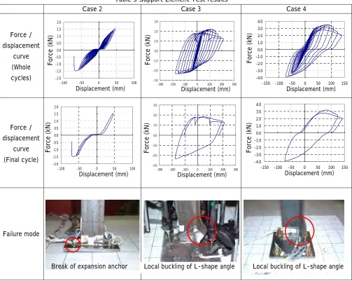
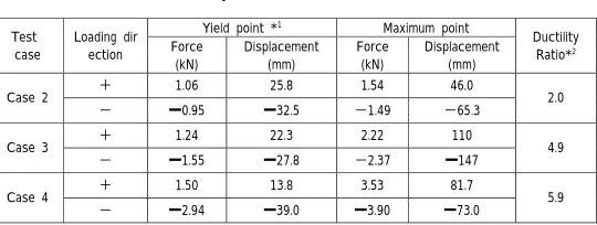
Test results for typical horizontal loading cases of cantilever supports are presented as belows. Table 3 shows the force-displacement curves and the snapshot after tests of Case 2 through Case 4. Table 4 shows the summary of these test results.
a) Case 2 [2B pipe, cantilever type support, expansion anchor (M6 bolt) ]
The cross section of anchor bolt screw was suddenly broken after the maximum horizontal cyclic loading of 1.49 kN on the minus side displacement of 65 mm.
From the force-displacement curve on piping, it was founded that the dissipated energy was so small because of the brittle failure of anchor bolt. And some gap originated from the slipping out of the anchor bolt was observed.
b) Case 3 [2B pipe, cantilever type support, embedded plate with studded bolts ( 16) ]
As the embedded plate was strongly-built with stud in the concrete block, force-displacement curve was reflected inelastic behavior of cantilever support. The curve gradually shows the local buckling mode near the bottom end of L-shape angle.
It was found that the ductile failure mode showed large dissipated energy at the maximum buckling load of 2.22kN on the plus side displacement of 110mm.
c) Case 4 [4B pipe, cantilever type support, expansion anchor (M12 bolt) ]
Force-displacement curve was reflected inelastic behavior of cantilever support similar to Case 3. The local buckling phenomena were observed at maximum load 3.53kN on plus side displacement of
81.7mm.
Test results of Case 2 4 support element test were summarized as follows. Remaining cases are under conducting tests now.
Brittle failure was observed for small expansion anchor of 2 B piping (Case 2). The ultimate strength or dissipated energies of this type of support was so poor that the damping effect would not be expected.
Embedded plate for 2B piping, or the expansion anchor for 4B piping (Case 3, 4) showed the ductile failure mode of L-shape angle. The ultimate strength or dissipated energies were large, compared to Case 2.
4. Seismic Proving Test Plan
Inelastic seismic tests of piping and support system are planned for two test models, which have different pipe size of 2B and 4B piping systems. Each piping system is designed as typical small bore piping of low temperature, made of carbon steel, Sch40.
Piping system has three dimensional routing, including elbows, tees, and nozzles, which will be probable to be used in actual plant systems.
Support is selected as most fragile type such as cantilever support with expansion anchor. Piping and support system is designed as same as the actual plant specifications.
4B piping system model shown in Fig.8 has been planned in order to verify the actual seismic strength over design level, using the E-defense vibration table at Miki city, which is the largest table in the world. Total length of the piping is about 30 meters, and number of supports is 16. On the other hand, 2B piping system model is shown in Fig.9, using the vibration table of Takasago Research and Development Center of MHI. Total length of the piping is about 17 meters with 7 supports, and the objective of test is same. Inelastic seismic test has scheduled the four phases (different excitation level or condition) of vibration test, as follows;
Phase 1 : s design earthquake level
Phase 2 : Excitation level over s, when at least one support would lose the function.
Phase 3 : Rearrangement of supports and excitation level around s, supposing the failure of some supports and removing them.
(1) Piping model
a) 4B piping system model
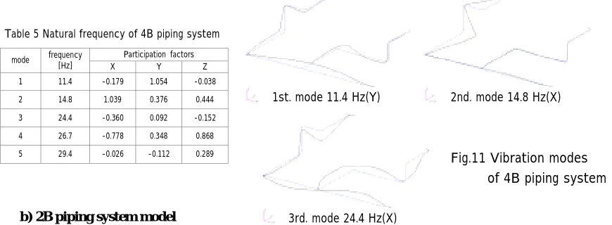
Fig.10 shows the whole structure of 4B piping system model. The model is a piping system with a piping bore of 100A, Sch40, which has eight elbows, one tee and three nozzles and is supported by sixteen supports. The test is aimed to study the elasto-plastic seismic response behavior of both supports and piping. The piping material is carbon steel. All the supports are the same as cantilever type with expansion anchor, which properties will be known from case 4 and case 7 of element tests. Natural frequency of 4B piping system is estimated in Table 5 and dominant modes are presented in Fig.11. Although the support design is based upon the standardized support span design method in Japanese PWR plant, natural frequency of this piping model shall be relatively low, because the most fragile type of support is selected. The conservative vibration conditions for excitation wave shall be determined in order to verify the ultimate strength of this typical piping system.
b) 2B piping system model
2B piping system model is a piping system with a piping bore of 50A, Sch40, which has five elbows and one tee, and is supported by eight cantilever type supports and three pin typed support. The objective of the test is as same as 4B model. All the cantilever type supports are with expansion anchors, which properties will be known from case 2 and case 6 of element tests. Natural frequency of 2B piping system is estimated in Table 6 and dominant modes are presented in Fig.12.
5. Conclusions
(1) The force-displacement characteristics or ductility ratio of typical fragile support will be obtained by support element tests. The expansion anchor for 4B piping (Case4) and the embedded plate for 2B piping (Case 3) show the ductile failure mode of support member. In such cases, relatively large dissipated energy will generate the damping effect of the piping system. On the other hand, the small expansion anchor for 2B piping (Case 2) shows the brittle failure mode of anchor bolt. It is important to take care to avoid such type of failure in the seismic re-evaluation program.
(2) The ultimate seismic strength of typical small bore piping will be made clear by the two kinds of seismic proving tests, which are 4B piping system model and 2B piping system model. The seismic safety of these typical piping systems will be proved.
(3) As the seismic responses of actual piping shall be affected by various factors, such as piping route, support configuration, and property of floor response spectrum, it is thought to be necessary to evaluate actual piping of the plant, considering each conditions by practical and rationalized method. The subjects to be resolved are as follows;
determination of allowable reaction force or ductility ratio for each support, considering the result of support element tests or other related works
methodology for detailed evaluation such as equivalent linearization method, considering the effect of stiffness reduction of support and accompanied damping
REFERENCES
1. Ito,T et al., “Proving test on the seismic reliability of the main steam piping system: Part 1”, ASME PVP, Vol.345,pp111~118. 1997
2. Tai,K et al., “Proving test on the seismic reliability of the main steam piping system: Part 2”, ASME PVP, Vol.345,pp119~124. 1997
3. Ito,T et al., “Performance of a multiple-excitation simulator at the seismic tests of a piping system supported by conventional snubbers”, ASME PVP, Vol.345,pp179~185. 1997 4. Tai,K et al., “Proving test on the seismic reliability of the main steam piping system
(Part 1: Simulation for PWR main steam piping”, 14th SMiRT, Vol.K, 1997 5. Namita,Y et al., “Seismic proving test of ultimate piping strength (Piping component test result
and simplified piping system test planning)”, ASME PVP, Vol.428-1,pp13~19. 2001 6. Suzuki,K et al., “Seismic proving test of ultimate piping strength (Test results on piping component
and simplified piping system)”, ASME PVP, Vol.445-1,pp99~106. 2002
7. Suzuki,K et al., “Seismic proving test of ultimate piping strength (Simulation analysis of simplified piping system test)”, ASME PVP, Vol.466,pp23~30. 2003
8. Suzuki,K et al., “Seismic proving test of ultimate piping strength (Status of design method confirmation test)”, 17th SMiRT, Vol.K5-2, 2003