International Journal of Innovative Research in Science, Engineering and Technology
An ISO 3297: 2007 Certified Organization Volume 6, Special Issue 4, March 2017
National Conference on Technological Advancements in Civil and Mechanical Engineering – (NCTACME'17)
17th -18th March 2017
Organized by
C. H. Mohammed Koya
KMEA Engineering College, Kerala- 683561, India
Enhancement of Surface Finish Using
Abrasive Flow Finishing (AFF) Process
Biju C.V1, Akhilesh P.R2
Associate Professor, Department of Mechanical Engineering, Jyothi Engineering College, Cheruthuruthy,
Thrissur, India 1
B.Tech Student, Department of Mechanical Engineering, Jyothi Engineering College, Cheruthuruthy, Thrissur, India 2
ABSTRACT: Around 70% of the engineering components such as cylinder liner of internal combustion engines, bearing races etc. are cylindrical in nature. Finishing of the same consumes considerable amount of time, energy and money in the industry. Because of the difficulty to access internally turned surfaces, the existing conventional finishing operations find its limitation in manufacturing engineering. The proposed work using centrifugal force assisted abrasive flow finishing (AFF) is a solution for this issue to a great extent. Two different abrasive materials, namely sand and ferrous powder (40mesh each) are used in the study. In order to avoid variations in clamping, out-side surfaces are also machined uniformly. Mild steel pipe having known material composition and 150BHN hardness is selected in the analysis. Using specially designed fixtures the specimens were mounted for AFF process. At each moment different grits are in contact with specific area of the piece. Rotation of the specimen provides relative movement of work-piece on abrasive. Centrifugal force acting on the abrasive grit produces necessary force towards radially outward direction. Along with centrifugal force, gravitation force also affects the contact force. The super-positioning of these two forces decides net force between work-piece and the grit. The set volume is filled with abrasives in all the trials. Since the temperature build up in the armature of the motor limits the AFF time into 30 minutes. Half masking strategy employed in the experiment, helps the investigation of the influence of AFF process with different abrasive materials. As the roughness of the specimen before AFF is almost impossible to be exactly uniform, percentage improvement approach is employed in the analysis. Using standard surface roughness tester, critical surfaces roughness parameters Ra, Rz, and Rq are compared for different experimental conditions. Consistent improvement of results is obtained from both qualitative and quantitative analysis. This shows the potential of proposed centrifugal force assisted AFF for internally turned components.
KEYWORDS: Abrasive flow finishing, surface parameters, centrifugal force, and Material removal rate
I. INTRODUCTION
Jain (2002) presented the need for the development of surface finishing technology for complicated shapes and proposed abrasive fine finishing process as a practical solution for the same. The finishing of surfaces having Ra (average surface roughness) less than 1µm is very costly and needs special techniques. More over the cost increases exponentially with the improvement of Ra value in this range. Rhodes (1991) and Loveless et.al (1994) reported AFF as an effective tool for radiusing, deburring, polishing and removal of recast layer of the work material. Both statistical and analytical methods were employed for the evaluation of the effectiveness of AFF in this study. Surface finish obtained by the partial removal of the peaks in the undulated surface is removed in AFF and material removal rate of the proposed technique is modeled in this work. Jain et.al (2001) identified percentage of abrasive, grain size, contact velocity etc are the influencing parameters of the surface finish obtained in AFF technique. The pressure exerted between abrasive grit and work-piece determines the level of MRR. Morever the ploughing effect which is a function of grit size and direction of flow are also studied in this work. The importance of maintain the contact velocity mentioned in this literature is strictly followed in the proposed work. The availability of free space in side hollow specimen is represented as percentage of volume filled is investigated in the study. Based on the literature survey two different grits, 70% volume, at 1480 rpm was set in the investigation.
Working Principle
The abrasive particle filled inside the hollow specimen was allowed to make contact with the inner surface of the work material. The rotating shaft of the motor was directly connected to work-piece. The dynamic frictional force between abrasives and surface to be finished impart rotation to the abrasive grits. This rotation constitutes centrifugal force on each grit radially outward direction.
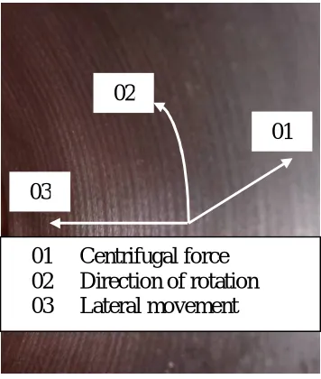
During AFF processes, work-material is ploughed by the fine abrasives grits which come in contact and they rub over the metal surface with high pressure. The material flow occurs in the direction of motion of the abrasive particle as well as in the lateral direction. The required pressure is built by the centrifugal force derived from the rotation of the grits about the axis of the work-material.
Based on the nature of external contact, abrasive grits are classified into two, namely primary and secondary. The grits directly comes contact with work-material are called primary grits, whereas those having contacts only with other abrasive grits alone is called secondary grits. The primary driving force is obtained from the rotation of motor. The shaft is connected to the flange and special design transfers rotation to the surface to be finished. The dynamic frictional force exerting on the primary grits with specimen, impart rotation to the grits. They transfer the energy to the secondary grits. During the process primary grits can change their role as secondary and vice versa. Figure 1 shows the concept of primary and secondary grits in the AFF process.
Fig.1 Classification of Primary and secondary grits
The size and density of the grit, rotation speed and inner diameter of the specimen, volume of abrasive filled etc. decides AFF time for required surface finish. The feed mark is helical in nature but rotation of the grit is in plane perpendicular to the axis of the work-piece. Due to this obstruction primary abrasive grits removes the peaks of the surfaces.
Work-material
Primary grits
Fig. 2 Schematic diagram of centrifugal force acting the abrasive Grit
Fig. 3 Photographic view of machined surface and direction of forces
Basically Abrasive Flow Finishing is material removal process consists of ploughing and rubbing operation, abrasive grit size plays vital role in the selection of the contact area. Figure 4 shows the schematic diagram of the ploughing process. The undulations on the surface, presently considered as surface roughness is modelled as triangular shape represented by dotted line consists both peaks and valleys.
Fig.4 Level of ploughing for different grit sizes of the abrasives
Almost all the existing finishing processes except filling of additional materials are working on the same principle. It comprises removal of peaks without affecting the existing valley levels. The selection of the grit size depends on feed marks of the machining processes applied on the work-material. Figure 4 shows the influence of abrasive grit on the ploughing intensity. Smaller grits often reduce the chance of lateral movement along the axial direction of the specimen which is very much needed in the AFF process.
01
02
03
01 Centrifugal force
02 Direction of rotation
03 Lateral movement
Rotation
Direction
Centrifugal
Force=mrω
2Abrasive
Grit
Bigger Grit
Smaller Grit
Peak
Material Characteristics
In the present investigation, a mild steel hollow tube was used. The outer and inner diameters are set as 60mm and 52 mm respectively. The material composition of the test specimen is shown in table-1. Since hardness of the material plays vital role in the material removal rate in the AFF process, using hardness test was conducted and Brinell hardness value was obtained as 150BHN. The work was held in the three jaw chuck for internal turning operation. To avoid clamping issues, outer surface was machined uniformly under identical machining conditions.
II. EXPERIMENTAL SET-UP
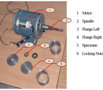
AC motor (Make: Lakshmi, India), Single phase prime mover 230V, 2A, 160 Watts, operating at 1440 constant rpm is used in the investigation. The uniform speed of the motor at wide range of torque helps to set constant angular speed for the wok-material. The fixture designed and fabricated for the study consists of spindle, flange and locking mechanism at both ends. The weight of the fixture without specimen and abrasive was measured as 1.10kg. The total weight including abrasive and specimen is 2.30kg. As this weight does not affect the shaft of the motor, the fixture with work-material was directly mounted on the prime mover. Figure 5 shows the components of the AFF in detail.
In order to maintain constant volume fill (70%) permanent marking was done inside the hollow cylinder. Each time the abrasives used in AFF process loss its original cutting edge, fresh abrasives particles were used in further trials. Special attempt has made to keep half part of the specimen free from AFF and it helps directly in the qualitative analysis. Sufficient care has taken to avoid slipping of specimen over spindle attached to the shaft of the motor.
Fig. 5 Components Used in AFF experimental Set-up
AFF Process
Two different abrasive particles, namely sand and ferrous powder each of mesh size 40, were used in the investigation. Since the contact pressure between primary grits and work-material is function of volume filled, 70% of the hollow specimens were filled with abrasive particles in both cases. Material removal rate MRR is a function of time, but the temperature built up in the armature of the coil restricts the AFF process continuously to a limit of 30 minutes.
Roughness measurement
Total nine specimens were prepared and roughness parameters Ra, Rz and Rq of these were measured at three different angular orientations. Even though machining of these were carried out in identical cutting conditions ( 380rpm, 0.5depth of cut and 0.18mm/rev feed), roughness parameters found to be varying by 15% in all the three parameters. Hence percentage improvement from the initial condition was set as the advantage of AFF in this investigation.
1
Motor
2
Spindle
3
Flange Left
4
Flange Right
5
Specimen
Half mask Approach
Literature high lights the need of consistency of the location for roughness measurement before and after the AFF process. But in this approach after AFF, the comparison between the initial and final becomes impossible. Hence a novel method called half mask approach is employed in this study. Another part having same curvature is fixed inside the specimen for one half of the work-piece. The special design prevents the contact of grits on this part during AFF process. Remaining circular half of the specimen was exposed to AFF. This approach avoids issues regarding non homogeneity of material, machining conditions variations during surface preparation of the specimen etc. At the end of the process the making element is removed and both the surfaces are compared both qualitatively and quantitatively.
Fig. 6 Surface Roughness Tester
Govt. Engineering College, Thrissur, Kerala
Surface roughness parameters Ra, Rq and Rz of the specimen were analysed quantitatively. Roughness tester (Make: Mitutoyo) having traverse length 5.60 mm and evaluation length 4.00 mm was selected in the measurement process. In order to avoid unwanted signals gauss filter was used. The averaging was done for the cut off length 0.80 mm. Sampling length was set as 1.5µm.
III. RESULTS AND DISCUSSION
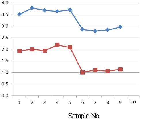
Out of the nine specimens prepared five were used for AFF with 40mesh sand grits and the remaining four was tested with iron powder grits. Fig. 7 shows the effect of abrasive material (iron powder over sand particles) on performance of AFF process. Percentage improvement which is a measure independent of initial conditions is shown in Fig. 8. Out of the nine samples first five samples were finished with sand. The remaining four were treated with iron powder.
Sample No.
Fig.7 Comparison of Ra value
S
ur
fa
ce
R
oughne
ss
R
a
(µ
m
Sample No.
Fig.8 Percentage of improvement of Ra
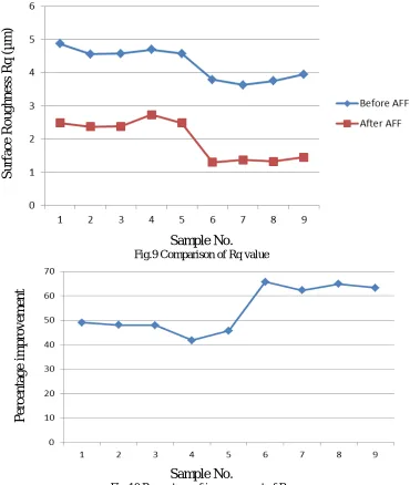
Root mean square value Rq is also measured and compared in the investigation. Consistent improvement is observed for Rq in both Sand and iron abrasive materials. But the level is found to significant in the latter case than the former. Fig. 9 shows the quantitative measure of Rq in nine specimens taken for study.
Sample No.
Fig.9 Comparison of Rq valueSample No.
Fig.10 Percentage of improvement of Rq
P
er
ce
nt
age
i
m
p
rove
m
ent
S
ur
fa
ce
R
oughne
ss
R
q
(µ
m
)
P
er
ce
nt
age
i
m
pr
ove
m
Another roughness parameter Rz which is calculated by averaging the vertical distances from the peak to the lowest valley with in five cut off length. It reflects the effect of extremes in the roughness profile. Comparison of Rz before and after the application of AFF is shown in Fig.11. Percentage improvement of Rz on both conditions is shown in Fig. 12.
Sample No.
Fig.11 Comparison of Rz value
Sample No.
Fig.12 Percentage of improvement of Rz
IV. CONCLUSION
1 Comparison of the performance of two abrasive material namely sand and ferrous powder of identical size are investigated in the Abrasive Finishing Process. The higher finish consistently obtained with ferrous powder in terms of all three parameters taken into consideration shows the importance of selection of abrasive particle. 2 Using half masking method it was possible to verify the improvement of surface finish on both circular portions
of the specimen. Both qualitative and quantitative analysis shows consistency in the result.
3 The mechanism behind the process shows the removals of peaks of the undulations were observed on the specimen is taken place with proper size of the grits so that valleys were not affected by the process.
4 The process found to robust and consistent. It is not seriously affected by the ambient temperature, humidity etc. 5 It is found to immaterial to magnetic and electric property of the work material.
S
ur
fa
ce
R
oughne
ss
R
z
(µ
m
)
P
er
ce
nt
age
i
m
pr
ove
m
V. ACKNOWLEDGEMENT
The authors thank Principal, Government Engineering College Thrissur, Head of the Department and faculty members of Production Engineering Department for providing Surface testing facility -under TEQUIP- at different stages of AFF investigation.
REFERENCES
[1] V.K. Jain, Advanced Machining Processes, Allied Publishers Pvt. Ltd., New-Delhi, 2002, pp. 57–76.
[2] L.J. Rhodes, Abrasive flow machining: a case study, Journal of Material Processing Technology 28 (1991) 107–116.
[3] T.R. Loveless, R.E. Willams, K.P. Rajurkar, A study of the effects of abrasive flow finishing on various machined surfaces, Journal of Material
Processing Technology 47 (1994) 133–151.
[4] V.K. Jain, C. Ranganatha, K. Muralidhar, Evaluation of rheological properties of medium for AFM process, Machining Science and