1 Active Stirling Engine
A thesis submitted in partial fulfilment of the requirements for the Degree
of Doctor of Philosophy in Electrical Engineering
in the University of Canterbury
by Vinod Kumar Gopal
University of Canterbury
2 Table of Contents
ACKNOWLEDGMENTS 12
ABSTRACT 14
GLOSSARY 16
1. INTRODUCTION AND HISTORY OF STIRLING ENGINE
DEVELOPMENT 22
1.1 Reverend Robert Stirling and his engine 23 1.2 Philips Stirling engine development 24 1.3 Other notable Stirling engine developments 28 1.4 Stirling engine development in Japan 29
1.5 Stirling engine development in US 29
1.6 Development in Stirling engine refrigeration and cryocooling 30
2. COMBINED HEAT AND POWER OR CHP SYSTEMS 34
2.1 Introduction to CHP systems 34
2.2 WhisperGen® microCHP systems 38
2.3 Control of existing microCHP systems 40
3. FUNDAMENTALS OF STIRLING ENGINES 44
3.1 Introduction to Stirling engine technology 44
3.2 Thermodynamic cycles 45
3 3.4 Ideal and conventional Stirling engines 51
3.5 Stirling engine control 55
3.6 Temperature control of Stirling engines 55 3.7 Pressure control of Stirling engines 55
3.8 Stroke control of Stirling engines 56
3.9 Phase control in Stirling engines 57
3.10 Dead volume control 58
3.11 Speed control 58
4. THE PROBLEM TO BE SOLVED 60
4.1 Effect of phase angle on Stirling engine performance 60 4.2 Controllability of current microCHP systems 61
4.3 Making use of phase control 64
4.4 Sinusoidal vs. non linear motion of reciprocating parts 64 4.5 Achieving phase control and non linear control 66
5. LITERATURE SURVEY 69
6. MODELING AND SIMULATION OF STIRLING ENGINES 80
6.1 Introduction 80
6.2 Zero order analysis and Beale equation 80
6.3 Modified Beale equation 81
6.4 First order analysis 83
6.5 Second order analysis 84
4
6.7 Third order analysis 86
6.8 CFD Modelling 88
7. SAGE SIMULATION MODEL FOR THE ASE 90
7.1 Spaces and boundary connections in Sage 91
7.2 Force connections in Sage 92
7.3 Pressure connections in Sage 92
7.4 Heat flow connections in Sage 92
7.5 Gas flow connections in Sage 93
7.6 Density connections in Sage 93
7.7 The Sage model of ASE 95
7.8 Geometry 96
7.9 Validation 97
8. THE ASE TEST RIG 99
8.1 ASE test rig details 99
9. LINEAR MACHINE IN DETAIL 106
9.1 Fundamentals of linear electrical machines 106 9.2 Cylindrical moving magnet linear motors 108
9.3 Flat linear motors 108
9.4 U-Channel linear motors 108
9.5 Linear machine for the ASE test rig 110
9.6 Home sensing 112
5
9.8 Commutation of a linear motor 113
9.9 Position feedback and encoder types 115
9.10 Encoder mounting 116
10. INSTRUMENTATION 120
10.1 Data acquisition system details 123
10.2 Different data acquisition modes 124
10.3 LabVIEW™ application block diagram 128
11. CALIBRATION 130
11.1 Pressure sensor calibration 130
11.2 Thermocouple and Flow sensor calibration 131 11.3 Test to account for ambient heat loss 132 11.4 Motion control system calibration 134 11.5 Analysis of errors and methodology 135
12. DISPLACER MOTION CONTROL SYSTEM AND TUNING 140
12.1 Servo tuning tutorial 142
12.2 Homing procedure for the linear motor 146
12.3 Closed loop feedback control 147
13. TEST METHOD AND MATRIX 150
13.1 Introduction to testing as an engine and a refrigerator 150 13.2 Work done by the Stirling engine and numerical integration 150
13.3 Engine testing 150
6
13.5 Refrigerator testing 154
13.6 Test Matrix- Refrigerator 155
14. ENGINE TEST RESULTS 157
14.1 Introduction to presentation of results 157
14.2 Refrigerator test results 176
14.3 Effect of working gas on Stirling engine performance 179
15. APPLICATIONS OF PHASE AND DWELL CONTROL IN
MICROCHP 181
16. CONCLUSIONS AND FUTURE WORK 184
17. REFERENCES 188
18. APPENDIX 1. TEST RIG DRAWING AND PICTURES 198
19. APPENDIX 2. OSCILLOMOTOR 204
20. APPENDIX 3. PRESSURE SENSOR RESPONSE TEST 208
21. APPENDIX 4. ACROBASIC SOFTWARE CODE FOR
7 Table of figures and tables
Figure 1-1 Reverend Robert Stirling and his engine [6] ... 23
Figure 2-1 MicroCHP system illustration [8] ... 36
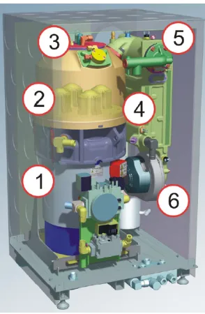
Figure 2-2 Inside the WhisperGen® microCHP system ... 41
Figure 3-1 PV Diagram of a Stirling engine ... 47
Figure 3-2 Sequence (compression-transfer-expansion-transfer) of ideal piston and displacer motions of a Stirling engine ... 49
Figure 3-3 Motion profile of an ideal Stirling engine [42] ... 50
Figure 3-4 Motion profile of a conventional Stirling engine [42] ... 53
Figure 3-5 Alpha, Beta and Gamma Stirling engine[42] ... 54
Figure 4-1 Proposed Active Stirling Engine concept ... 67
Figure 4-2 Non linear displacer motion for ASE test rig ... 68
Figure 7-1 Sage simulation model of the ASE. ... 95
Figure 8-1 Block diagram of the ASE test rig ... 99
Figure 8-2 Linear machine top view. ... 101
Figure 8-3 Linear machine side view. ... 102
Figure 8-4 The ASE test rig ... 103
Figure 9-1 U channel ironless linear motor [53] ... 109
8 Figure 9-3 Linear motor cross section. The section is perpendicular to the
travel. [53] ... 111
Figure 9-4 Misalignment of encoder and scale [53] ... 117
Figure 9-5 Magnetic and optical encoders mounted on the linear motor ... 118
Figure 10-1 Two encoders mounted at the end of the rotary shaft of 3phase alternator... 121
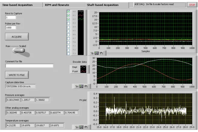
Figure 10-2 LabVIEW™ User interface for shaft based acquisition... 125
Figure 10-3 LabVIEW™ User interface for time based acquisition ... 126
Figure 10-4 LabVIEW™ Block diagram ... 128
Figure 10-5 LabVIEW™ Block diagram continued ... 129
Figure 11-1 Photograph of heating coil wound over the heater head. The coil is held in place by a metallic sleeve ... 133
Figure 11-2 Picture of the optical linear encoder measuring piston position 135 Figure 12-1 Motion control software algorithm; continued ... 144
Figure 12-2 Motion control software algorithm... 145
Figure 12-3 Motion control system with closed loop feedback control ... 148
Figure 14-1 PV diagram comparison with sinusoidal displacer motion and non-linear displacer motion at 750 RPM and constant power input . 158 Figure 14-2 Heater head temperature, Input power and rejected power with respect to the phase angle at 750 RPM and constant power input .... 159
9 Figure 14-4 PV diagram comparison with sinusoidal displacer motion and
non-linear displacer motion at 500 RPM and constant power input . 161
Figure 14-5 Heater head temperature, Input power and rejected power with respect to the phase angle at 500 RPM and constant power input .... 162
Figure 14-6 PV Power and Thermodynamic efficiency with respect to phase angle at 500 RPM and constant power input ... 163
Figure 14-7 PV diagram comparison with sinusoidal displacer motion and non-linear displacer motion at 750 RPM and constant heater head temperature ... 164
Figure 14-8 Heater head temperature, Input power and rejected power with respect to the phase angle at 750 RPM and constant heater head temperature ... 164
Figure 14-9 PV Power and Thermodynamic efficiency with respect to phase angle at 750 RPM and constant heater head temperature ... 165
Figure 14-10 Efficiency vs. Phase angle vs. dwell at 750 RPM and constant power input ... 166
Figure 14-11 Heater head temperature vs. Phase angle vs. dwell at 750 RPM and constant power input ... 167
Figure 14-12 Efficiency vs. Phase angle vs. dwell at 500RPM and constant power input ... 168
Figure 14-13 Heater head temperature vs. Phase angle vs. dwell at 500 RPM and constant power input ... 169
Figure 14-14 PV diagram at different phase angles for sinusoidal motion at 750 RPM ... 170
10 Figure 14-16 Piston position, displacer position and engine pressure at
various phase angles for sinusoidal motion... 171
Figure 14-17 PV diagram at different phase angles for 50% dwell at 750 RPM ... 172
Figure 14-18 Motion profile showing piston motion and displacer motion at different phase angles for 50% dwell ... 173
Figure 14-19 Piston position, displacer position and engine pressure at various phase angles for 50% dwell ... 174
Figure 14-20 PV Power vs. Phase angle at 750RPM. Simulation and experimental. ... 175
Figure 14-21 Plot 100. PV Diagram with sinusoidal displacer motion and with 50% dwell. ... 177
Figure 14-22 Plot 101. Motion profile of piston and displacer ... 177
Figure 14-23 Plot 102. Lift and COP of the refrigerator with respect to the head temperature at sinusoidal and 50% dwell ... 178
Figure 14-24 Plot 102. COP and %Carnot COP vs. Carnot COP for sinusoidal displacer motion and with 50% dwell. ... 178
Figure 18-1. Drawing of the engine part of ASE test rig ... 198
Figure 18-2. Cold end of the engine... 199
Figure 18-3. Cold end of ASE showing the fins ... 199
Figure 18-4. Displacer inserted into the cold end. The other end of the displacer comes out through a seal and is connected to the linear motor ... 199
Figure 18-5. Heater head connected to the engine block ... 200
11 Figure 18-7. Photographed when the linear machine is working at 750RPM201
Figure 18-8. Linear machine track and magnets ... 201
Figure 18-9. Burned heater head coil during an inadvertent short circuit ... 202
Figure 18-10. Insulator used on the heater head after six months use ... 202
Figure 18-11. Coolant bypass valve and the flow sensor ... 203
Figure 19-1. Drawings of the oscillomotor with counter rotating rotors ... 205
Figure 19-2. Oscillomotor with counter rotating rotors before pasting the high power Nd-Fe magnets ... 206
Figure 19-3. Photograph of the assembled oscillomotor ... 206
Figure 20-1Pressure sensors in preparation for a test to measure step response ... 208
Figure 20-2 Response of the two pressure sensors. Sampling rate is 5kHz and the Y axis shows pressure in Bars ... 209
Table 4-1 Data showing operation of 62 WhisperGen® systems………..62
Table 11-1 Sensors used, reolution and accuracy ...136
Table 11-2 Raw data file. Only 20 rows are shown instead of 5000...137
Table 11-3 Post processed master worksheet averaging results of multiple experiments performed with the same parameters...138
12 Acknowledgments
I wish to express my sincere appreciation to Late Associate Professor Richard Duke for supervising me and making me stay focused throughout this research. I wish to thank Dr. Don Clucas whose idea sowed the seed and helped shape the outcome of this research. I express my sincere gratitude to Dave Fanner, Josh Baker, Lincoln Frost and Michael Gschwendtner for assisting me in this project. I wish to thank Dr. Paul Gaynor for editing this thesis.
This thesis is dedicated to my Late Mother Mrs. Meenakshi Kunjamma (my Paaru). She spent all her life to bring me up to be a responsible and educated person. I would not even be in engineering school without her love, hard work and unconditional support.
13 “To my Amma, for everything, that will ever be me, for teaching me what
14 Abstract
Micro Combined Heat and Power systems or microCHP systems generate heat and electricity for a home. Stirling engines are widely used as prime movers in microCHP applications. Stirling engine is an external combustion engine having an enclosed working fluid (as helium) that is alternately compressed and expanded to operate a piston. The displacer shuttles the working fluid between the hot and cold ends. The piston is coupled to a transmission and to an electrical machine to generate power. Conventional Stirling engines are not controllable to a great degree. The piston and displacer are connected to the same crank and they maintain the same phase difference throughout the cycle. Also the piston and displacer are normally constructed to move in a sinusoidal fashion.
15 This thesis examines the effect of non-linear displacer motion and phase control of the displacer on Stirling engine performance. Simulations are performed in Sage, the leading Stirling engine simulation software, to understand the effect of displacer phase control. A test rig is constructed with the actively controlled displacer connected to a linear machine controlled by a programmable servo. Heat is applied to the test rig though an electric heating coil. The test rig is charged with nitrogen at 20Bar pressure. The power piston is connected to a rotating electrical machine via the transmission. The rotating electrical machine is used to start the engine and to act as the generator.
The test rig is instrumented to determine the linear position of the displacer and piston, angular position of the rotating electrical machine shaft, temperatures, pressures and flow. A LabVIEW™ based data acquisition system is set up to capture data from the test rig. Data is collected at various test cases. The simulation result is compared against post processed data.
16 Glossary
ASE. Actively Controlled Stirling engine or Active Stirling Engine. In this type of Stirling engine, the displacer will be disconnected from the main crank and will be driven separately. The engine will have the capability to change phase and dwell, on the fly.
Burner. A device, as in a furnace, stove, or gas lamp that is lighted to produce a flame.
Cycle. A thermodynamic cycle consists of a series of thermodynamic processes transferring heat and work, while varying pressure, temperature, and other state variables, eventually returning a system to its initial state. In the process of going through this cycle, the system may perform work on its surroundings, thereby acting as a heat engine.
Data Acquisition System. Data acquisition is the process of sampling signals that measure real world physical conditions and converting the resulting samples into digital numeric values that can be manipulated by a computer. Data acquisition systems (abbreviated with the acronym DAS or
17
Displacer. A displacer shuttles the working fluid between the cold and hot ends in a Stirling engine.
Encoder. An encoder is a device that converts information from one format to another. A linear encoder similarly converts linear position to an electronic signal. Such encoders can be either absolute or incremental. The signal from an absolute encoder gives an unambiguous position within the travel range without requiring knowledge of any previous position. The signal from an incremental encoder is cyclical, thus ambiguous, and requires counting of cycles to maintain absolute position within the travel range. Both can provide the same accuracy, but the absolute encoder is more robust to interruptions in transducer signal.
Generator. In electricity generation, an electric generator is a device that converts mechanical energy to electrical energy. A generator forces electrons in the windings to flow through the external electrical circuit. It is somewhat analogous to a water pump, which creates a flow of water but does not create the water inside.
18
Heat exchanger. A heat exchanger is a piece of equipment built for efficient heat transfer from one medium to another. The media may be separated by a solid wall, so that they never mix, or they may be in direct contact.
Linear Motor. A motor which works in the linear direction and reverses at the end of travel.
microCHP. Micro Combined Heat and Power system. A home appliance
replacing conventional boilers used to heat a home or dwelling. MicroCHP systems generate heat and electricity for a home.
Numerical integration. In numerical analysis, numerical integration constitutes a broad family of algorithms for calculating the numerical value of a definite integral, and by extension, the term is also sometimes used to describe the numerical solution of differential equations.
Open and closed cycle. A closed cycle reuses the working fluid while an open cycle exhausts it.
19 and is made gas-tight by piston rings. In an engine, its purpose is to transfer force from expanding gas in the cylinder to the crankshaft via a piston rod and/or connecting rod. In a pump, the function is reversed and force is transferred from the crankshaft to the piston for the purpose of compressing or ejecting the fluid in the cylinder. Piston is housed in a cylinder.
Primary coolant. Primary coolant collects the heat from the cylinder and transfers it to the secondary coolant through a heat exchanger
PV Diagram. A pressure volume diagram is used to describe a thermal
cycle involving the following two variables; Volume (on the X axis) and Pressure (on the Y axis). The diagrams are useful when one wants to calculate the work done by the system, the integral of the pressure with respect to volume. One can often quickly calculate this using the PV diagram as it is simply the area enclosed by the cycle.
20 thermal efficiency of the cycle to approach the limiting Carnot efficiency defined by those maxima and minima.
Servo. Servomechanism or servo is a device used to provide control of a desired operation through the use of feedback. The term correctly applies only to systems where the feedback or error-correction signals help control mechanical position, speed or other parameters.
Stirling engine. An external combustion engine used as a prime mover.
Thermocouple. A thermocouple is a device consisting of two different conductors (usually metal alloys) that produce a voltage proportional to a temperature difference between either ends of the pair of conductors.
Transmission. A mechanism to convert linear motion into rotary motion. A transmission transmits the power generated by the piston to the load.
22 1. Introduction and History of Stirling engine
Development
Stirling machines are a form of heat engine using expansion and compression at different temperatures of a gaseous working fluid for their operation. They incorporate a novel component, a thermal regenerator [1]; a form of heat exchanger [2] acting as a thermodynamic sponge alternately accepting and rejecting heat to and from the working fluid. This helps in recycling a major fraction of the energy flow from one cycle [3] to the next. Stirling engines exhibit high thermal efficiencies between given temperature limits because of the regenerator. Stirling machines may be used as a prime mover [4], accepting heat from a high temperature source, converting some of the heat to work and rejecting heat at a lower temperature. They may also be used as a refrigerator or heat pump, lifting heat from a low temperature source and rejecting it at a higher temperature with an input of work.
23 engine is not controllable and difficult to balance. Due to these reasons, kinematic Stirling engines are considered for the application.
1.1 Reverend Robert Stirling and his engine
The Stirling engine was invented in 1816 by Reverend Robert Stirling a Minister in the Church of Scotland. Robert Stirling and his brother James, one of the leading engineers of the time, worked on regenerative systems for many years [5]. The Stirling brothers made a number of engines some of which were used in practical applications. In those days similar machines were called air engines or hot-air engines or caloric engines with the name of the inventor prefixed.
24 The name ‘Stirling Engines’ was coined to embrace all types of closed cycle regenerative gas engines regardless of the identity of the working fluid. The generic title ‘Ericsson Engines’ [7] was used to embrace all types of open cycle valve regenerative gas engines. Throughout the 19th century hot air engines were made and used in relatively large numbers. The early air engines were used in a variety of applications, mainly generation of power and pumping water [8]. The history of these early air engines has been well surveyed by Finkelstein [9] and by Sier [10].
Stirling engines enjoyed substantial commercial success around 1900. The lack of suitable materials hampered its further development and the improvements in internal combustion engines and electrical machines led to its eventual demise [5].
1.2 Philips Stirling engine development
25 speed and power density to any other previous generation Stirling engines. However, improvements in thermionic valve design and the invention of electronic transistors and subsequent development of dry battery powered transistor radios eliminated the need for the market for which the engine was intended. The history and technology of the Philips Stirling developments has been written in detail in an interesting book by Hargreaves [11].
26 developed at the Philips laboratories while Ford concentrated on the vehicle installation, drive train and other aspects [12].
27 General Motors Corporation for use in GM's hybrid electric car. Re-configured as a Power Unit, it was designed to deliver a rated capacity of 10 kW of electricity and 20kW of heat. The 10 kW Power Unit will measure approximately 3ft * 3ft * 2ft (about the size of a small residential air conditioning unit).
28 (then Kockums) announced a licensing agreement with MAN-MWM to produce a 600kW V12 engine. This was probably to be used as the main propulsion unit for non nuclear, air independent submarines. As the former USSR broke up and the threat to Scandinavian countries was removed, the programme was abandoned [8].
1.3 Other notable Stirling engine developments
29 1.4 Stirling engine development in Japan
In the late 1970’s the Japanese entered the Stirling engine field in a substantial way. The Japanese Government Ministry of International Trade funded the R&D work on four engines from 3kW to 30kW. They were natural gas fired and were intended to be used as cogeneration systems and drivers for heat pumps. In 1977, a consortium of British universities and industries including BP Plc, embarked on an ambitious project to produce six 2 cylinder 20kW Stirling engines. Novel features like ceramic pistons and a heat pipe system were experimented with [8].
1.5 Stirling engine development in US
30 collect and focus solar energy on to a power conversion unit (PCU), which generates electricity. The system consists of a solar concentrator in a dish structure that supports an array of curved glass mirror facets. These mirrors collect and concentrate solar energy into grid-quality electricity. The conversion process in the PCU involves a closed-loop, high-efficiency four-cylinder reciprocating Stirling Engine.. A total of 60 SunCatcher™ Power Systems have been operating since January 2010. Prototypes of the system have been running for over two decades which provided the learning to design the current systems.
1.6 Development in Stirling engine refrigeration and cryocooling
31 were very effective refrigerators when motored. The commercial prospect was identified as a very low temperature refrigerator to achieve cryogenic temperatures (Below 110K). Cryocoolers [16] are used in spacecraft for a variety of purposes. Principal applications are for cooling infrared detectors and high temperature superconductor research. Cryocoolers are also used to prevent evaporation in cryogenic fuel tanks. Cryogenic engineering is a specialist field involved with the separation and purification of gases [17] . This technology has lot of applications in medical, education, commercial, Industrial, food preservation and metallurgy. The book by Graham Walker (1983) summarises the technology of cryogenic refrigerators [18].
Philips recognized the commercial possibilities of the Stirling cryocooler. A separate team was established to develop it as a commercial product under the leadership of Dr. Kohler. He is recognized as the father of the cryocooler.
32 substantial liquid air production. It is estimated that Philips sold around 15000 of these cryogenic units and recovered most of their investment in the Stirling engine programme. The principle field of application of Stirling cryocoolers turned out to be a very miniature form and not the large systems as Philips envisaged. These miniature cryocoolers are used to cool the infrared detectors of night vision equipment and missile guidance systems. The surfaces of the infrared detectors are responsive to particular wavelengths at very low temperatures [19]. The infrared chips needed electrically driven closed cycle cryocoolers in the field and a market for these kind of cryocoolers emerged by late 1950’s/early 1960’s. As electronics technology advanced, the infrared chips became smaller and the refrigeration requirements diminished. [8]
34 2. Combined Heat and Power or CHP systems
2.1 Introduction to CHP systems
In some energy applications, energy is required in multiple forms. These energy forms typically include some combination of heating, ventilation, and air conditioning, mechanical energy and electric power. Often, these additional forms of energy are produced by a heat engine, running on a source of high-temperature heat [20]. A heat engine can never have perfect efficiency, according to the second law of thermodynamics [21], therefore a heat engine will always produce a surplus of low-temperature heat or waste heat. This heat is useful for heating applications even though it is not practical to transport heat energy over long distances, unlike electricity or fuel energy.
An energy efficient system must generate electricity near locations where the waste heat can be put to good use. This is known as a combined heat and power (CHP) system, or "cogeneration" [22].
35 A CHP system works mainly from the heat demand. Fuel input to the CHP plant is restricted, reducing both the heat and power output to balance the heat demand. In doing this, the power production is limited by the heat demand.
CHP systems are able to increase the total energy utilization of primary energy sources, such as fuel and concentrated solar thermal energy. Thus CHP has been steadily gaining popularity in all sectors of the energy economy, due to the increased costs of fuels, particularly oil-based fuels, and due to environmental concerns, particularly climate change.
In a traditional power plant delivering electricity to consumers, about 30% of the heat content of the primary heat energy source, such as biomass, coal, solar thermal, natural gas, petroleum or uranium, reaches the consumer, although the efficiency can be 20% for very old plants and 45% for newer gas plants. In contrast, a CHP system converts 10%–25% of the primary heat to electricity, and most of the remaining heat is captured for hot water or space heating. In total, as much as up to 93% of the heat from the primary energy source goes to useful purposes when heat production does not exceed the demand.
36 domestic boiler [23]. When operating, the microCHP system generates both electricity and hot water. The electricity produced is available for use in the house or exported to the national grid and the hot water is used for both central heating and domestic hot water. The electrical efficiency of microCHP systems in development is 10 to 25% and overall energy recovery efficiency is above 90%. The use of a microCHP system can play an important role in the effort to reduce atmospheric pollution and carbon dioxide emissions, a leading contributor to climate change. Better efficiency will also allow better utilisation of natural resources.
Figure 2-1 MicroCHP system illustration [8]
37 cells [25] and internal combustion engines [26]. MicroCHP is not economically viable in many markets around the world. MicroCHP systems need to be efficient to generate more electricity and provide a better payback. This thesis explores the potential of improving the efficiency and manufacturing cost of microCHP systems.
To date, microCHP systems achieve much of their savings, and thus attractiveness to consumers, through a net metering model [27] wherein home-generated power exceeding the instantaneous in-home needs is sold back to the electrical utility. This system is efficient because the electricity generated is distributed and used instantaneously over the electrical grid. The main losses are in the transmission from the source to the consumer, which will typically be less than losses incurred by storing energy locally or generating power at less than the peak efficiency of the microCHP system. Therefore from a purely technical standpoint dynamic demand management [28] and net-metering are very efficient.
38 2.2 WhisperGen® microCHP systems
There are various technologies used for the prime mover in the microCHP space. The leading ones are kinematic Stirling engines, free piston Stirling engines and fuel cells. Internal combustion engines are not generally preferred due to the noise levels and service requirements. During the time of this research, only one microCHP system was commercially available. This was the WhisperGen® microCHP manufactured in Christchurch, New Zealand and deployed in Europe. All other microCHP systems were undergoing early trials or in experimental stage of development. Due to this reason, the WhisperGen system is analysed in detail.
39 operate on a principle that heated gas expands and the cooled gas compresses. For the WhisperGen® system, a mixture of air and fuel is burned in an external combustion burner, which heats up the finned heater heads of the Stirling engine. Heat is transferred through the finned heater heads to heat nitrogen gas within four cylinders. The heated nitrogen gas expands in the top hot heat exchanger and is then moved to the lower water cooled cylinder where it contracts. Cooling water removes heat from the cold cylinder and is used for domestic water heating. Central heating water returns through the exhaust heat exchanger, where it is pre-heated by the hot gases from the engine exhaust. Water then passes to a water jacket in the engine, where it is heated further and in the process provides cooling for the “cold end” of the engine. Resulting hot water is then piped out to the heating system. At times of high heat demand an auxiliary burner provides additional heating.
40 phase squirrel cage induction machine [31] is used as the electrical generator in the WhisperGen® .
2.3 Control of existing microCHP systems
In microCHP systems, electric power is generated when the system is running. Primary control of microCHP systems is the heat demand signal, which starts and stops the engine. MicroCHP systems are sized to handle the average thermal load of a house. An auxiliary burner (also called the boost burner) is used in the system to increase the thermal output as and when required. The auxiliary burner is coupled to the main exhaust heat exchanger and is turned on to increase the heat output.
In normal operation, the auxiliary burner is switched on and off to achieve the control aspect (outer control loop) for the heating. The disadvantage of using an auxiliary burner is that the energy going into the auxiliary burner is not generating electricity. This part of the system works like a conventional boiler.
41
Figure 2-2 Inside the WhisperGen® microCHP system
A drawing of the WhisperGen® microCHP system is shown in Figure 2.2. The primary set point for the system is the heat demand signal provided by the central heating controller.
1. An electrical generator that provides 230V AC power
2. A Stirling engine that provides motive power for the generator
42 4. A heat exchanger that recovers heat from the hot gases produced by the burner
5. An auxiliary burner that provides additional heat at times of high heat demand
6. An exhaust fan connected to a balanced flue [32]. This provides the combustion air for the burner and passes the hot gases from the combustion process through the heat exchanger to the atmosphere
43 an induction generator with a positive slip and exports the power generated to the utility grid. Once the system is exporting electricity, a control system regulates the fuel burning rate to set the operating point to 1kW electricity generation.
44 3. Fundamentals of Stirling Engines
3.1 Introduction to Stirling engine technology
Heat engines are generally described in terms of cyclic processes in which a gas absorbs heat at a high temperature, releases heat at a lower temperature and performs an amount of work. Carnot [34] showed in the 1820s that the maximum theoretical efficiency available from a reversible heat engine depends only on the temperature change in the cycle [35].
η = W
Qe = 1- Tc
Te
(3.1)
Where η is the efficiency, W (Joules) is the work done by the engine, Qe (Joules) is the heat fed to the engine, Tc (Kelvin) is the temperature at which heat is rejected and Te (Kelvin) is the temperature at which heat is absorbed.
45 facilitate the analysis of operation, a repeated sequence of the thermodynamic process called the cycle is assumed.
3.2 Thermodynamic cycles
A thermodynamic cycle consists of a series of thermodynamic processes transferring heat and work, while varying pressure, temperature, and other state variables, eventually returning a system to its initial state [36]. In the process of going through this cycle, the system may perform work on its surroundings, thereby acting as a heat engine.
State quantities depend only on the thermodynamic state, and cumulative variation of such properties adds up to zero during a cycle. Process quantities (or path quantities), such as heat and work are process dependent, and cumulative heat and work are non-zero. The first law of thermodynamics dictates that the net heat input is equal to the net work output over any cycle. The repeating nature of the process path allows for continuous operation, making the cycle an important concept in thermodynamics. Thermodynamic cycles often use quasistatic processes [37] to model the workings of actual devices.
46 motor vehicles. Power cycles can be divided according to the type of heat engine they seek to model. The Otto cycle [38] models gasoline engines and the diesel cycle [39] models diesel engines, both of which are internal combustion engines. Brayton cycle [40] models gas turbines and jet engines. Rankine cycle [41] models steam turbines. Brayton and Rankine cycles model external combustion engines.
Two primary classes of thermodynamic cycles are power cycles and heat pump cycles [3]. Power cycles are cycles which convert some heat input into a mechanical work output, while heat pump cycles transfer heat from low to high temperatures using mechanical work input. Cycles composed entirely of quasistatic processes can operate as power or heat pump cycles by controlling the process direction. On a pressure volume diagram [36] the clockwise and counterclockwise directions indicate power and heat pump cycles, respectively.
47 diagram as it is simply the area enclosed by the cycle. For an ideal system the net variation in state properties during a thermodynamic cycle is zero, it forms a closed loop on a PV diagram. A PV diagram's Y axis shows pressure (P) and X axis shows volume (V) as shown in Figure 3-1.
Figure 3-1 PV Diagram of a Stirling engine
The area enclosed by the loop is the net work (W) done by the process:
W= ∮PdV (3.2)
This work is equal to the balance of heat (Q) transferred into the system:
48 Equation (3.3) makes a cyclic process similar to an isothermal (infinite heat transfer) process: even though the internal energy changes during the course of the cyclic process, when the cyclic process finishes the system's energy is the same as the energy it had when the process began. If the cyclic process moves clockwise around the loop, then W will be positive, and it represents a heat engine. If it moves counterclockwise, then W will be negative, and it represents a heat pump.
A Stirling machine is a device which operates on a closed regenerative thermodynamic cycle [3] with cyclic compression and expansion of the working fluid at different temperature levels, and where the flow is controlled by volume changes so that there is a net conversion of heat to work and vice versa. Stirling machines are capable of operating as prime movers, heat pumps, refrigerating engines or pressure generators.
3.3 The Stirling cycle
49 converted to work and part of it is rejected as heat at a lower temperature Tc. The displacer is used to transfer the gas between hot and cold ends and should not be confused with the power piston.
Figure 3-2 Sequence (compression-transfer-expansion-transfer) of ideal piston and displacer motions of a Stirling engine
50 volume is the unswept internal volume. A typical design is a stack of fine metal wire meshes, with low porosity to reduce dead space, and with the wire axes perpendicular to the gas flow to reduce conduction in that direction and to maximize convective heat transfer.
Figure 3-3 Motion profile of an ideal Stirling engine [42]
Figure 3-3 shows the motion profile of an ideal Stirling engine. Process 1-2 is isothermal compression. Heat is transferred from the working fluid at temperature Tc to the external dump
51 Process 3-4 is isothermal expansion. Heat is transferred to the working fluid at temperature Th from an external source
Process 4-1 is the constant volume transfer of gas from the hot section to the cold section. Heat transfer takes place to the regenerator from the working fluid
If the heat transferred in process 2-3 has the same magnitude as in process 4-1, then the only heat transfers between the engine and its surroundings are heat supply at Th and heat rejection at Tc. This heat supply and heat rejection at constant temperature satisfies the requirement of the second law of thermodynamics for maximum thermal efficiency, so that the efficiency of the Stirling cycle is same as that of the Carnot cycle. The principal advantage of the Stirling cycle over the Carnot cycle lies in the replacement of two isentropic processes by two isochoric processes, which increases the area of the PV diagram. Therefore to obtain a reasonable amount of work from the Stirling cycle, it is not necessary to resort to very high pressures and swept volumes as in a Carnot cycle.
3.4 Ideal and conventional Stirling engines
52 thermodynamically reversible and that the process of compression and expansion are isothermal, thereby implying infinite rates of heat transfer between the cylinder walls and the working fluid. It is also assumed that all the working fluid is either taking part in the expansion or compression process so that effects of any voids in the regenerator matrix, clearance spaces and pockets contributing to dead volume were neglected. Regeneration is assumed to be perfect with an infinite rate of heat transfer between the regenerator matrix and the working fluid. Also the piston and the displacer were assumed to move in some discontinuous fashion to achieve the working fluid distribution. All fluid dynamic and mechanical friction and leakage effects were neglected. In any practical engine, all these factors contribute towards achieving a thermal efficiency well below the Carnot value of the ideal Stirling cycle. The actual thermal efficiency may be quoted as a fraction of the theoretical Carnot efficiency. A value in excess of 0.3 is evidence of a well designed Stirling engine [12].
53 limitations due to inertial forces and elasticity.
In a conventional engine, the piston and the displacer will be moving in a nearly sinusoidal manner. The piston and displacer motion profiles of a conventional Stirling engine are shown in Figure (3-4). In the operation of this engine, a significant departure from the ideal arises as a consequence of the near sinusoidal motion of the pistons. The compression and expansion do not take place wholly in one or other of the two spaces.
Figure 3-4 Motion profile of a conventional Stirling engine [42]
54 1500 RPM) it is likely that the compression and expansion processes are becoming adiabatic (no heat transfer) and not isothermal. To improve the heat transfer, special heat exchangers are required at the hot and cold ends. These heat exchangers increase flow losses and dead volume which affects the system efficiency.
The mechanical arrangements of Stirling engines are generally divided into three groups known as Alpha, Beta and Gamma arrangements [43]. Alpha engines have a pair of sealed pistons in separate cylinders, which are connected in series by a heater, a regenerator and a cooler. Both Beta and Gamma arrangements are defined by the use of a classic piston-displacer arrangement, the Beta type having them both in the same cylinder and the Gamma type in separate cylinders [44]
55 3.5 Stirling engine control
The power output of a Stirling engine depends on a variety of factors including the temperature of the hot and cold ends, the swept volume to total unswept working gas volume ratio, the phase angle by which the volume variations in the expansion space lead those in the compression space, the mean cycle pressure of the working fluid, the speed of the engine and the dynamic characteristics of the load coupled to the engine. Ideally speaking, all the above mentioned parameters can be used to control and regulate the power output or operating speed of the engine.
3.6 Temperature control of Stirling engines
Conventional microCHP systems use temperature control of the heater heads. The control system regulates the fuel supplied to the burner system to control the hot end temperature to effectively output the power produced at steady state. As the thermal inertia in the system is high, the response is sluggish, often taking many minutes to reach steady state.
3.7 Pressure control of Stirling engines
56 working space through a control valve was used. A temporary decrease happens in the engine output when fluid is admitted as the cold fluid needs to come up to the working temperature. However, after this initial transient, the increased pressure increases the power output. A decrease in power output is accomplished by release of the working fluid from the working space. The released fluid is compressed and stored back in the reservoir.
3.8 Stroke control of Stirling engines
57 3.9 Phase control in Stirling engines
In a Stirling engine the volume variations in the expansion space leads the volume variations in the compression space by a phase angle α. This ensures that heat is absorbed by the expansion space and rejected from the compression space. When the phase angle is zero, the pistons move synchronously but in anti-phase. The volume and pressure ratios are very high, but no useful work is done. The PV diagram is a single vertical line and the area enclosed is nil. As the phase angle increases, the power output increases approaching a maximum value at about 90° and decreasing thereafter with further increase in the phase angle. When the phase angle approaches 180° the pistons move synchronously and sympathetically pushing the working fluid from the compression space to the expansion and vice versa. The total volume of the working space remains constant and there is only a slight change in pressure. This is due to the change in the temperature of the working fluid from a minimum value when the compression space volume is a maximum to a maximum value when the expansion space volume is a maximum. No work is done however for there is no change in the total working space volume. PV diagram is again a vertical line with the area enclosed being nil.
58 roles of two spaces. The expansion space absorbing heat becomes the compression space and vice versa. The power output is negative indicating that an input of power is required to drive the unit. If input power is available to drive the engine, it will continue to run in the forward direction acting as a heat pump or refrigerator, absorbing heat at low temperature and rejecting heat at high temperature. Phase control is instantaneous. Conventional engines have not explored this control scheme and the Active Stirling Engine attempts to explore this control mechanism for kinematic Stirling engines.
3.10 Dead volume control
Variation of the dead space within the total working space volume can be achieved by connecting different size reservoirs in the crank case of the engine. Valves can be used to cut in and out specific dead volumes as a control scheme even though it is not efficient or easy to perform.
3.11 Speed control
59 operate over a wide range of speed and power levels.
60 4. The problem to be solved
4.1 Effect of phase angle on Stirling engine performance
Stirling engines have a hot end and a cold end. Heat is supplied to the hot end and heat is rejected at the cold end. The displacer shuttles the working gas from the hot end to the cold end and vice versa. The expanding gas pushes the power piston to generate work. In conventional engines, the displacer and piston are connected to the same crank. The displacer leads the piston by a phase angle of approximately 90°. Some engines operate on a phase angle as high as 120°. Even though it can be set to any phase angle, published literature suggests highest power output to be around 90°. One main investigation in this thesis is the effect of phase angle between displacer and the power piston on the performance of a Stirling engine. The variables of interest are indicated power, efficiency, heater head temperature, rejected heat and the pressure variation inside the engine. This thesis investigates the relationship of these variables with respect to the phase angle.
61 percentage of the total duration of a cycle. For example if an engine is operating at 600 Hz, its cycle time is 100 milliseconds. If the dwell of the displacer is 50%, the displacer stays at the dead centers for a total of 50 milliseconds and travels from one dead center to the other and back in 50 milliseconds to complete a cycle. Hence the transition time from one dead center to the other will be 25 milliseconds and the rest time at each dead center will be 25 milliseconds.
When the displacer motion is sinusoidal, the expansion and compression does not take place completely in the respective cylinder. When the motion profile is changed from sinusoidal to the one with dwell, the working gas gets more time during the cycle to expand in the expansion cylinder and to get compressed in the compression cylinder. This property of utilizing the motion profile with dwell will improve the thermodynamics and the total work done by the system. As the work done is the same for the same input power, the efficiency increases due to the dwell. This thesis investigates to confirm this property by practical experimentation and to find out the quantum of efficiency increase.
4.2 Controllability of current microCHP systems
62 systems employ ON-OFF control for the auxiliary burner and primary burner. The system turns off when the primary coolant reaches the set temperature and turns on when the coolant temperature hits the lower level. Table 4-1 shows the hours of operation of main burner and auxiliary burners on a sample of 62 WhisperGen® microCHP systems running for a total of 92,730 hours. These engines were part of a customer trial conducted in United Kingdom by Whisper Tech Ltd.
# of engines Hours # of starts KWH generated
Boost burner running hours
62 92730 124067 79317 10662
Average 1496 2001 1279 172
Table: 4-1. Data showing operation of 62 WhisperGen® systems
63 starting, the engine has to be brought up to the working temperature, cranking has to be set, coolant flow has to be monitored and the burner has to be brought up to the right amount of fuel flow and temperature. The seals and guides will experience a higher wear when the engine starts from rest. Similarly while stopping an engine, the burner is switched off or modulated down, the engine winds down in power until the energy export becomes zero, the engine is motored from that instant to operate like a refrigerator to bring the heater head temperatures down to avoid temperature damage to the seals. Head temperatures are monitored and the engines shut down at an appropriate instant. The seals and guides experience a higher wear and tear while the engine is started or stopped compared to while running.
64 4.3 Making use of phase control
Heat management algorithms may be able to make use of phase control to reduce start and stops, which will improve the life of the engine. Also intelligent central heating controllers provide a PWM signal, which may be made use of by a phase control mechanism to adjust the amount of heat and electricity generated. This is also a subject of investigation in this thesis.
Phase angle control has been investigated previously as a method of power control for Stirling engines. As the power output of the Stirling engine is related to the sine of phase angle between the piston and displacer, changing the phase angle has a direct impact on the power output of the engine. Changing the phase angle from the optimum value actually detunes the engine. Prior art and previous research on the effect of phase angle on Stirling engine performance is discussed in detail in Chapter 5.
4.4 Sinusoidal vs. non linear motion of reciprocating parts
65 whether a non linear displacer motion with dwell at both ends of the stroke can increase the work done and/or efficiency of the engine compared to sinusoidal displacer motion.
In an ideal Stirling engine, most of the expansion has to take place in the hot end or the expansion cylinder and the compression or contraction should take place in the cold cylinder or compression space. In a practical Stirling engine, due to the sinusoidal motion of the piston and displacer, expansion and compression happens in both the cylinders. A move towards ideality will require non linear motion of the piston and the displacer. In this research, the displacer motion is made non linear (with dwell at both the ends of the stroke) to explore the impact of departure from sinusoidal motion. It is assumed that the enclosed area of the PV diagram will enlarge and the indicated power and efficiency of an engine will increase due to the non linear displacer motion and better thermodynamic response.
Equation 4-1 shows the relationship between the work done and the area enclosed by the PV diagram in an ideal Stirling engine.
W= Qe- Qc= ∮p dVe- ∮p dVc (4.1)
66 volume diagram and the compression space pressure volume diagram reveal the net work done by a Stirling cycle engine. The proposed scheme allows the closed integral to be larger due to the non linear motion and hence relates to an increase in the power produced by the Stirling engine.
4.5 Achieving phase control and non linear control
To achieve phase control and non linear motion of the displacer, the displacer is disconnected from the crank and driven separately by a linear electrical machine and its servo drive. The term “Active Stirling Engine” [45] is coined to describe systems where the displacer is actively controlled with respect to the piston. Actively controlled Stirling engine or the Active Stirling engine (ASE) is capable to control the displacer motion trajectory based on an external command signal.
67
Figure 4-1 Proposed Active Stirling Engine concept
68
Figure 4-2 Non linear displacer motion for ASE test rig
This project investigates whether it is beneficial in high temperature high speed machines. Figure 4-2 shows the sinusoidal motion of displacer and piston in a conventional Stirling engine along with the proposed non linear motion of displacer with dwell at both ends of stroke. In addition to non linear motion, the displacer will have the ability to employ phase control so that its effects also can be investigated as explained earlier. Data represented in Figure 4-2 is collected from one of the experiments when a Stirling engine is run at 750 RPM with sinusoidal and nonlinear displacer motion.
Motion Profile. 750 RPM
-5 0 5 10 15 20
1 501 1001 1501 2001 2501
Sample number (1000 Samples per Revolution)
69 5. Literature survey
Free displacer engines with a kinematic piston are called Ringbom Stirling engines [46]. In Ringbom engines, displacer control is not possible as it has a free displacer, which works only under gas pressures. Free piston engines with a kinematic displacer drive are termed Martini Stirling engines [44]. The Martini displacer is the name given to machines in which the displacer is driven by a motor that is independent of the power piston movements and the pressure changes. Martini patented such a system to provide power for blood pumping in an artificial heart. This was like a thermo mechanical amplifier in which a small effort expended in moving the displacer causes substantial pressure changes which acting upon the power piston can produce a much greater effect.
70 except the displacer shaft is brought out of the pressure vessel and the linear machine resides outside the pressure vessel.
Brian P. Nuel and Samuel P. Weaver disclose methods for displacer control using electrical machines [47]. Methods incorporating a solenoid, a rotary motor and a linear stepper motor are explained. Moloney discloses a mechanical arrangement to achieve dwell at end of strokes for both displacer and piston [48]. This technique needs physical control of the parameters and therefore electronic control is difficult to implement. Also phase control is not implemented. The mechanical system is complicated and making the bearings survive for the expected service life of a microCHP application is difficult. Walsh discloses a resonant free piston Stirling engine with a virtual rod displacer and linear electrodynamic machine control of displacer drive and damping [49]. The displacer stroke and phase angle is controlled in this scheme. This technique cannot implement dwell. Also as the engine is free piston, the resonant operation can be achieved only over a small speed range. The machine is not balanced and will have unacceptable vibrations while operating.
71 cylindrical motor coils. A position control system is used to control the displacer. This kind of arrangement is suitable for a cryocooler and not for a microCHP application. In a cryo cooler, the displacer end is cold and for a microCHP application it is on the hot side. The electrical windings and magnets cannot survive in the displacer enclosure without affecting performance. Walsh discloses a free piston Stirling engine with displacer control [51]. The control is used for starting up the system and to modulate power output. This method effectively uses the controlled displacer as a starting aid and is employing stroke control of the linear displacer. Dwell and phase control which is the investigation carried out in this thesis is not examined.
74 Berchowitz discloses a double acting Stirling engine phase control mechanism for power control of Stirling machines [64]. The aforementioned three references are designed for automotive systems and not suitable for a microCHP application. They only use phase control as a means to control power and not efficiency. Also non liner motion of the displacer is not considered. Kenneth D. Price discloses a three stage electromechanical damper for a Stirling refrigerator displacer [65]. This is used as a phase control method. Bamberg and O’Neil discloses a variable stroke control for the piston of a cryocooler for temperature control [66]. The two references mentioned above are suitable for cryocoolers and refrigerators. Attempt is made to control the stroke of the displacer.
75 control element which opens or closes the inlet depending on the differential pressure present [69]. This is very complex in construction and the efficiency is affected. Biermann discloses a stroke control mechanism using the assistance of a circular arc shaped lever arm [70]. This is a mechanical arrangement which offers only stroke control.
76 and cold sides. The valve can be controlled by the feedback from speed, stroke or power of the engine. But the dwell cannot be used or controlled. This is mainly designed for an automotive application and not for a microCHP. Holliday [76] discloses a stroke control system for a hybrid power system employing a free piston Stirling engine. Nommensen discloses a Stirling engine with two chambers and rotatable rotor disks coupled to a common output shaft [77]. One-way valves or adjustable nozzle valves are used for regulating flow of working fluid to achieve power control. Horn discloses a displacer drive with dwell for a cryogenic cooler to improve the cooling efficiency [78]. The displacer drive is controlled by two solenoids, which fire the displacer to hot and cold end while holding at either of the stops to increase dwell time. This technique is suitable for cryocoolers and not for Stirling engines operating at high temperature for a microCHP application
77 In a series of studies of large engines intended for use as locomotives and large off-highway rubber tyred vehicle propulsion engines, Walker [8]. proposed the use of phase control as the means to achieve regenerative braking when stopping or descending a grade. By advancing the phase angle beyond 180° the engine was converted to operate as a heat pump, so that heat was absorbed at ambient temperature and rejected at high temperature to a high temperature thermal store of lithium fluoride for subsequent use in driving the engine. The energy required to drive the propulsion motor as a heat pump was provided by the kinetic energy of the train or truck when braking to a stop or by the potential energy when descending a grade. Walker showed that even with conservative assumptions, loaded mine trucks descending a grade could extract and store enough energy to drive the empty truck halfway back to the load site before new fuel was required.
78 reference publication, the global efficiency and the power of the engine are plotted vs. phase angle. Surprisingly the efficiency is lower for a discontinuous displacer motion compared to sinusoidal motion, which is not what is found during this research. Lloyd [81] is using a driven displacer for a low temperature differential Stirling engine for power production. A stepper motor is used to drive the displacer with dwell at low speeds. This technique is similar to what is used in this thesis for a microCHP application. A linear motor is used instead of a stepper motor, the heat source is at high temperature and the engine speed is twice than that mentioned.
79 pump drive [44] by Moynihan and Ackermann, 1984 with a linear motor drive for displacer. The power piston is a metal diaphragm and is used to pump hydraulic fluid which in turn is used to operate the compressor of a less conventional heat pump. Chen et al. explores the phase shift characteristics for cryocoolers [85].
80 6. Modeling and Simulation of Stirling engines
6.1 Introduction
Theoretical aspects of Stirling engines have been developed with varying degrees of sophistication. These are generally classified as orders of analysis, i.e., zeroeth order is the most simple, then first order and second order and the highest level is third order analysis. Third order analysis is an attempt to map exactly the process occurring in a Stirling machine. This classification was done by William Martini [14]
6.2 Zero order analysis and Beale equation
Zero order analysis is based on experience. William Beale [54] of Sunpower, Inc. was the first to note in the 1960’s the actual performance of many Stirling engines could be expressed in terms of an equation
W = 0.015 p f V0 (6.1)
81 for quick calculations to determine the size or output or variability of a new Stirling engine. Beale’s equation was specifically concerned with the customary temperature regimes for Stirling engines of about 700°C for the hot side and about 30°C for the cold side. A fundamental justification of the Beale equation was later developed by James Senft and by Colin West [44].
6.3 Modified Beale equation
Changes introduced by Senft and West modified the equations to include the effects of hot and cold temperatures. These are particularly helpful in applications using low temperature differential and for heat pump applications. The Zeroeth order recommendation by West [44] is
W = 0.025 p f V0 (Th – Tc) / (Th + Tc) (6.2)
where W is the work output in watts, p is the mean cylinder pressure in pascal, f is the operating frequency in hertz, V0 is the swept volume of the compression space in m3, Th is the hot space temperature in Kelvin, and Tc is the cold space temperature in Kelvin.
82 COPRefrigerator = Heat lifted / Work done (6.3)
It is customary to refer this in terms of the Carnot value
COPCarnot = Tcold space / (Tambient – Tcold space) (6.4)
Relative efficiency of a refrigerator can be expressed as
COPRelative = COP / COPCarnot (6.5)
COP of a heat pump is the ratio of heat rejected to the work done
COPHP = Heat rejected / Work done (6.6)
This is by definition a factor of unity larger than the equivalent ratio used for refrigerators.
COPHP = (Heat lifted + Work done) / Work done (6.7)
COPHP = COPRefrigerator + 1 (6.8)
83 the useful product of its operation is the quantity of heat expelled at higher temperature [8]
6.4 First order analysis
84 gas is assumed, perfect mixing of the gas in cylinders is assumed and leakage past the seals is neglected. These sweeping assumptions make the results predicted very optimistic. Despite the disadvantages, it is fairly easy to analyse and provides closed form solutions.
Following Schmidt’s derivation of the isothermal model, the next significant advance in Stirling theory was forwarded by Theodore Finkelstein in 1960 and is known as the “limited heat transfer theory” [86]. This theory allows for heat transfer between the working fluid and cylinder walls to take any prescribed value between the two extremes of isothermal (infinite heat transfer) and adiabatic (zero heat transfer). The Finkelstein theory does not have a closed form solution and involves solving various simultaneous partial differential equations which are tedious to resolve.
6.5 Second order analysis
85 separately and are assumed to occur independently of the other losses in the machine. Isothermal-based decoupled analysis tends to be optimistic and adiabatic based decoupled analysis tends to be pessimistic compared to actual performance values of experimental engines.
6.6 Simulation programs for Stirling engine analysis
There have been several simulation programs for Stirling engine analysis. West [44] has provided a listing and critique on 20 different programs. William Martini, in a study commissioned by NASA incorporated the second order decoupled analysis [14] in a computer program for personal computers. His reports are the most extensive exposition of the second order analysis technique including a discussion of the various thermal and frictional parasitic losses and the equations for their estimation. Following the death of William Martini, Marvin Weiss and his colleagues rewrote the program. Separate versions were devised for power systems (MARWEISS) and cryocoolers (CRYOWEISS. [8] [44].
86 user modifiable. Prof. Thomas of Germany has developed a program for second order analysis (PROSA) which is used for sinusoidal Stirling engine analysis [88]. It was used in the initial stages of analyzing the Active Stirling Engine test rig and to understand its characteristics. The program has a provision for optimizing up-to ten variables at a time.
6.7 Third order analysis
![Figure 2-1 MicroCHP system illustration [8]](https://thumb-us.123doks.com/thumbv2/123dok_us/9039888.400315/36.612.163.469.351.554/figure-microchp-system-illustration.webp)