IJEDR1504162
International Journal of Engineering Development and Research (www.ijedr.org)913
Comparitive Analysis of Power Quality for
Non-Linear System with D-STATCOM Using PI ,Fuzzy
and Neuro-Fuzzy Controllers
1Mr. Ashish kumar, 2Mr.Ashish sahu 1PG Student, 2Assistant professor
1,2Department of Electrical Engineering, RCET, Bhilai , India
________________________________________________________________________________________________________
Abstract- This paper describes the compensation of effects of non-linear load in a system using DSTATCOM with different controller approach. The non-linear load causes power quality deterioration in system. The objective of this paper is to damped out harmonics in the system and compensate reactive power. FACTS technology is entirely based on power electronics devices which are used to increase the transmission capability. To make the transmission system flexible and operated independently, as these FACTS devices increases the maximum load ability of the transmission lines which may be constrained by a transient as well as steady state stability limits. The main objective of paper is aimed towards the benefits of utilizing FACTS devices with the purpose of improving the operation of an electrical power system. The performance of the proposed DSTATCOM system is verified through simulations using MATLAB software with its Simulink.
IndexTerms - Flexible Alternating Current Transmission System(FACTS), Distributed Static Compensator (DSTATCOM).
________________________________________________________________________________________________________
I.INTRODUCTION
The present day ac power distribution systems are suffering from severe power quality problems , the main causes for these issues is non-linear loads connected to distribution side. Power quality problems include high reactive power burden, harmonics currents, load unbalance and excessive neutral current etc. A group of controllers together called Custom Power Devices, which includes the FACTS devices [2].
FACTS initiative in the late 1980s with two main objectives: to increase the power-transfer capability of transmission systems and to keep power flow over designated routes Without any doubt, the implementation of the above objectives requires effective power flow control methodologies. Meanwhile, by using circuit reactance, voltage magnitude, and angle as controls to change system power flow patterns, FACTS technology affords unique control flexibility and versatility, which also presents daunting challenges in power flow control to power system operators and researchers. With the further development of power electronics technologies, more and more FACTS devices are expected to be designed and applied in the future. Since various FACTS devices possess different physical models and different control parameters, as far as power flow control is concerned, it is desirable to formulate a versatile model which enables realization of power flow control incorporating any type of FACTS devices [1].
Fig.1. Non- linear system with FACTS device
IJEDR1504162
International Journal of Engineering Development and Research (www.ijedr.org)914
II. DISTRIBUTEDSTATICSYNCRONOUSCOMPENSATOR(DSTATCOM)A D-STATCOM (Distribution Static Compensator), which is consists of a two-level Voltage Source Converter (VSC), a dc energy storage device, a coupling transformer connected in shunt to the distribution network through a coupling transformer as in figure 2. The VSC converts the dc voltage across the storage device into a set of three-phase ac output voltages. These voltages are in phase and coupled with the ac system through the reactance of the coupling transformer. Suitable adjustment of the phase and magnitude of the D-STATCOM output voltages allows effective control of active and reactive power exchanges between the D-STATCOM and the ac system. Such configuration allows the device to absorb or generate controllable active and reactive power, as well as cancel out harmonics .[5]
Fig .2 .Schematic diagram of DSTATCOM
III.CONTROLOFDSTATCOM
There are two control objectives implemented in the DSTATCOM. One is the ac voltage regulation of the power system at the bus where the DSTATCOM is connected and the other is dc voltage control across the capacitor inside the DSTATCOM. It is widely known that shunt reactive power injection can be used to control the bus voltage. In conventional control scheme, there are two voltage regulators designed for these purposes: ac voltage regulator for bus voltage control and dc voltage regulator for capacitor voltage control. In the simplest strategy, both the regulators are proportional integral (PI) type controllers. Thus, the shunt current is split into d-axis and q-axis components. The reference values for these currents are obtained by separate PI regulators from dc voltage and ac-bus voltage errors, respectively. Then, subsequently, these reference currents are regulated by another set of PI regulators whose outputs are the d-axis and q-axis control voltages for the DSTATCOM.[act filter] figure 3 shows the basic close loop control action in DSTATCOM as the firing of the power circuit is fed through a hysteresis comparator .
Fig.3. Close loop Control of DSTATCOM
PWM firing pulse generated for triggering for voltage source inverter. Pulse width modulation is basically the switch on and off of different interval of time to make output nearly sine wave. [7]
From the single line diagram
IJEDR1504162
International Journal of Engineering Development and Research (www.ijedr.org)915
The utility voltage is given byV
S(t) =V
msin(ωt)
(2)The load current will have a fundamental component and the harmonic components which can be represented as
IL
(t) = ∑
∞n=1I
nsin(nωt + φn)
(3)
I
L(t) = I
Lsin(ωt + φ1 ) + ∑
∞n=2I
nsin(nωt + φn)
(4) Instantaneous load power PL (t) can be expressed asP
L(t) = V
S(t) *I
L(t)
(5)
P
L(t)= V
msin(𝜔𝑡)
* I
Lsin(ωt+Φ1 ) +
V
msin
𝜔
t *
∑
∞n=2I
nsin(nωt + φn )
(6)
P
L(t)=V
msin ωt
*
I
L[
sin
ω
t ∗ cos
φ
1 + sin
φ
1 ∗ cos
ω
t
] + V
msin ωt
*
∑
∞n=2I
nsin(nωt + φn )
(7)
P
R(t)=V
m*I
L(sin ωt)
2∗ cos φ1
(8)
P
LP
Rare real and reactive power in the system.
TOTAL HARMONIC DISTORTION=
𝐼
𝑇𝐻𝐷=
√I2 2+𝐼32+𝐼42+⋯………
𝐼1
× 100
(9)
IV.NEURO-FUZZY CONTROL
This controller gives the combination of two intelligent system as neural network and Fuzzy system the basic architecture shown in fig. 6 . The requisite part of Neuro-Fuzzy structure comes from a common framework called adaptive network which combine the neural network and the Fuzzy system. In the given hybrid intelligent system, neural network have the potentiality to recognize patterns and adapt them to cope with different environment. On other hand the Fuzzy inference system incorporates human knowledge and performs inference and decision making ability.
FUZZY LOGIC
Fuzzy logic systems are one of the main developments and successes of Fuzzy sets and Fuzzy logic. It is a rule-base system that implements a nonlinear mapping between its inputs and outputs. A Fuzzy logic system is characterized by four modules.
Fuzzifier
Defuzzifier
Inference engine
Rule base
IJEDR1504162
International Journal of Engineering Development and Research (www.ijedr.org)916
Fig.4. FUZZY ControllerFig.5 Describe the firing approach of DSTATACOM for power quality improvement .
Fig.5. Fuzzy logic control loop
NUERAL NETWORK
In addition to being the source of natural intelligence, the human brain can process incomplete information obtained by perception at a very rapid rate. In this architecture the neurons or the processing units which are interconnected by weights are expected to mimic the human brain. As they gave the neural network the capability for learning and adaptation by adjusting the interconnection between the layers.
The important characteristics of the neural network are:
Presence of a large number of simple units
Presence of a large number of highly parallel units
Presence of strongly connected units
Robustness against the failure of single units
Learning from data
The network of any system will be considered to be an artificial neural network if the same basis function is used during the network. As the nodes of the system is called the neurons.
The layers of neural network architecture may be subdivided into three principal groups:
Depending upon the number of inputs all the input neurons together constitute the input layer.
Similarly all the output neurons together constitute the output layer.
All the neurons in any intermediate layer form the hidden layer. It is possible that may be more than one hidden layer in a neural network.
IJEDR1504162
International Journal of Engineering Development and Research (www.ijedr.org)917
Fig.6. Neuro-Fuzzy inputand output layersFig 7. shows the Adaptive Nuero-Fuzzy approach to firing the DSTATCOM with hysteresis comparator for the power quality improvement
Fig.7. Neuro-Fuzzy control loop
V.SIMULATIONRESULTS
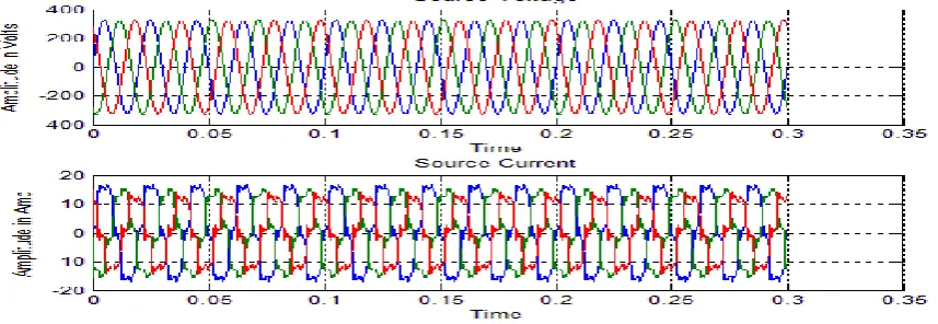
The Simulation results is taken in 3Φ system with unbalance load and non-linear elements having the total harmonic distortion of 22.24% which is injected to the system .The simulation results are compare with 3 different controllers i.e. PI, fuzzy and Neuro-Fuzzy controller .
Case-1 Simulation results of electrical system with unbalance and non-linear load
Simulation results of source voltage, source current ,load voltage and current and source power and load
power with respect to time.
IJEDR1504162
International Journal of Engineering Development and Research (www.ijedr.org)918
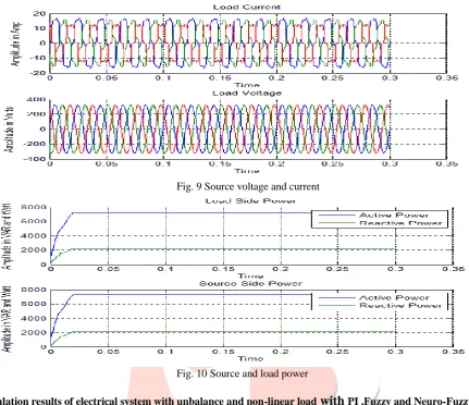
Fig. 9 Source voltage and currentFig. 10 Source and load power
Case-2 Simulation results of electrical system with unbalance and non-linear load
with
PI ,Fuzzy and Neuro-Fuzzy Controllersa. PI Controller
Fig. 11 Source voltage and current
IJEDR1504162
International Journal of Engineering Development and Research (www.ijedr.org)919
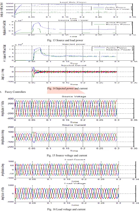
Fig. 13 Source and load powerFig. 14 Injected power and current b. Fuzzy Controllers
Fig. 15 Source voltage and current
IJEDR1504162
International Journal of Engineering Development and Research (www.ijedr.org)920
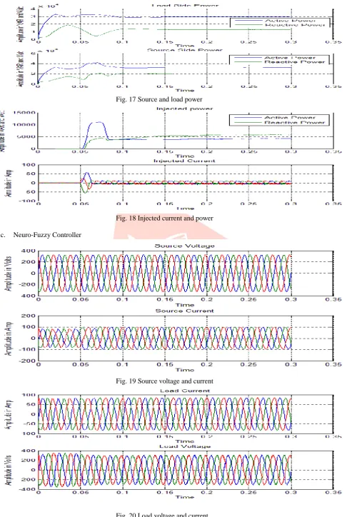
Fig. 17 Source and load powerFig. 18 Injected current and power
c. Neuro-Fuzzy Controller
Fig. 19 Source voltage and current
IJEDR1504162
International Journal of Engineering Development and Research (www.ijedr.org)921
Fig. 21 Source and load powerFig. 22 Injected current and power
Based on the Simulation results with different conditions and controller used the conclusion are in Table 1 .
Table 1 Table Type Styles
S.no. Parameter PI FUZZY NEURO-
FUZZY
1. Source
current IS
Distorted Less distortion
Less distorted
2. Load
voltage VL
Distorted Less distortion
Less distortion
3. Load
Current IL
Distorted Less distortion
Less distortion
4. Source
power PS
Distorted Less distortion
Less distortion
5. Load
power PL
Distorted Less distortion
Less distortion
6. Injected
power PI
Distorted Less distortion
Less distortion
7. Injected
current II
Distorted Less distortion
Less distortion
8. Total
harmonic distortion
Distorted Less distortion
IJEDR1504162
International Journal of Engineering Development and Research (www.ijedr.org)922
VI.CONCLUSIONIn this work different controller was developed and verified for three phase four wire systems. Even though DSTATCOM with PI controllers are capable of compensating current harmonics in 3 phase 4-wire systems, it can be seen that the Fuzzy Logic and Neuro-Fuzzy controller has a better dynamic performance than the conventional PI controller. PWM pattern generation based on carrier current fed firing angle control for inverter control gives also fast response for controlling power quality of the system.
REFERENCES
[1] Ying Xiao and Y.H. Song, ”Power flow control approach to power system with embedded FACTS devices,” IEEE Vol-17 No.-04, Nov-2002.
[2] Ranjit Kumar Bindal ,” A Review of benefits of FACTS devices in power system,” IJEAT, Vol-3, Aprile-2014. [3] S. Khalid and Bharti Dwivedi, “Power quality issues , problems, standards and their effects in industry with corrective means,” IJAET, Vol-6 .
[4] Sai Kiran Kumar, Y. Naveen Kumar and D. Archan “Power quality improvement in distribution system using DSTATCOM in transmission lines,” IJERA, Vol-01.
[5] R. chudamani , M.A. Mulla and Alpesh Mahyavanshi “Reactive power compensation by controlling the DSTATCOM ,” IJERA, Vol-2, Nov-2012.
[6] Mahesh K. Mishra, Arindam Ghosh, and Avinash Joshi,” Operation of a DSTATCOM in Voltage Control Mode,” IEEE, VOL . 18, NO. 1, Jan 2003.
[7]