MODEL DQ215
DISC CONTROLLER
INSTRUCTION MANUAL
DISTRIBUTED·
MODEL
DQ215
DISC CONTROLLER
INSTRUCTION MANUAL
March 1984
mil
DISTRIBUTED LOGIC CORPORATION
nmm
~~6~ ~~;~n2~gir Street Anaheim. California 92806
I I Telephone: (714) 937·5700 Telex: 6836051
Copyright © 1984 by Distributed Logic Corporation
TABLE OF CONTENTS
Section Page
1 DESCRIPTION ... ; ... 1-1 INTRODUCTION ... ' ... 1-1 CONTROLLER CHARACTERISTICS ... 1-1 LSI-II Q-BUS INTERFACE ... 1-2 INTERRUPT ... 1-3 DISC INTERFACE ... 1-3 OPERATING SYSTEM COMPATIBILITY ... 1-3 CONTROLLER SPECIFICATIONS ... 1-4
2 INSTALLATION ... , ... 2-1 INSPECTION ... 2-1 PRE-INSTALLATION CHECKS ... 2-3 INSTALLATION ... 2-3 GROUNDING ... 2-4
3 OPERATION ... '" ... 3-1 INTRODUCTION ... 3·1 PRECAUTIONS AND PREOPERATIONAL CHECKS ... 3·1 BOOTSTRAP PROCEDURE ... 3-1 FORMAT AND DIAGNOSTIC TEST PROGRAM ... 3-2 Description ... 3-2 Partitioning Program ... 3-7 Diagnostic Test Program ... 3-12 EPROM FORMAT PROGRAM ... 3-12
TABLE OF CONTENTS (Continued)
Section Page
Drive Status Register ... 4-9 Error Register. . . . 4-10 Attention Summary and Offset Register ... 4-11 Desired Cylinder Address Register ... ' ... 4-12 Extended Memory Address Register (22-Bit) ... 4-12 ReadIWrite Buffer Register ... 4-13 Maintenance Register 1 ... , ... 4-13 ECC Position Register ... 4-13 ECC Pattern Register ... 4-14 Maintenance Register 2 ... 4-14 Maintenance Register 3 ... ; .. , ... 4-14 Enable Real Time Clock Control Register ... 4-14
5 TROUBLESHOOTING AND THEORY ... 5-1 BASIC SYSTEM TROUBLESHOOTING ... 5-1 CONTROLLER SYMPTOMS ... 5-1 PHYSICAL LAYOUT ... 5-1 TERM LISTING ... 5-1 THEORY ... " .... 5-5 Computer Interface ... ' ... ; ... 5-5 Disc Interface . . . .. . . . ; . . . 5-6 Controller Internal Functions . . . '. . . . 5-6 Data Buffer ... , ... 5-7 ERROR CORRECTION CODE (ECC) LOGIC ... 5-7 FunctionalOperation ... 5-7 Component Description ... 5-7 +12 VOLT TO -5 VOLT POWER SUPPLY ... 5-9
LOGICS
Figure
1-1 2-1 2-2 3-1 3-2(A) 2-3(B) 4-1 5-1 5-2 5-3
Table
I-I 1-2 1-3 2-1 2-2 3-1 4-1 5-1 5-2
ILLUSTRATIONS
Page
Disc Controller System Simplified Diagram ... I-I Controller Configuration. . . .... 2-1 Typical Backplane Configuration ... 2-4 Partitions ... 3-2 Universal Firmware-Format . . . 3-8 Universal Format-Change Parameters ... 3-9 Controller Register Configuration . . . 4-4 Board Layout . . . 5-3 Simplified Block Diagram ... 5-6 Data Paths ... 5-8
TABLES
Page
Controller/Q-Bus Interface Lines ... 1-2 Controller To Drive 1/0 Interface-" A" Cable . . . 1-3 Controller To Drive 110 Interface-"B" Cable ... 1-3 Configuration Switches ... 2-2 Jumper Installation ... 2-2 Values for Partitioning with Universal Firmware (DQ215) ... 3-3 Function Codes ... 4-1 Controller Symptoms ... 5-2 Term Listing ... ',' ... ' ... 5-4
SECTION 1
DESCRIPTION
INTRODUCTION
This manual describes the installation, operation, programming, troubleshooting, and theory of opera-tion of Distributed Logic Corporaopera-tion (DILOG) Model DQ2I5 Disc Controller. The controller inter-faces DEC* LSI-II based computer systems to one or two SMD 110 disc drives, including 8- and I4-inch Winchester, SMD pack and CMD cartridge type drives. The complete controller occupies one quad module in the backplane. Full sector buffering in the controller matches the transfer rate of the disc drive and the CPU. The controller is compatible with RK06/RK07 software drivers in RT-II, RSX-II and RSTS.
CONTROLLER CHARACTERISTICS
The disc controller links the LSI-II computer to one or two disc storage units. Commands from the computer are received and interpreted by the con-troller and translated into a form compatible with the disc units. Buffering and signal timing for data transfers between the computer and the discs are performed by the controller.
*DEC. RSX and RSTS are registered trademarks of Digital Equipment Corporation.
LSI-11 Q BUS
CONTROL (14)
CONTROL (15)
DATA (16)1 ADDRESS (22)
CONTROL (8)
POWER GROUND
COMPUTER INTERFACE
A microprocessor is the sequence and timing center of the controller. The control information is stored as firmware instructions in read-only-memory (ROM) on the controller board. One section of the ROM contains a diagnostic program that tests the functional operation of the controller. This self-test is performed automatically each time power is applied. A green diagnostic indicator on the con-troller board lights if self-test passes.
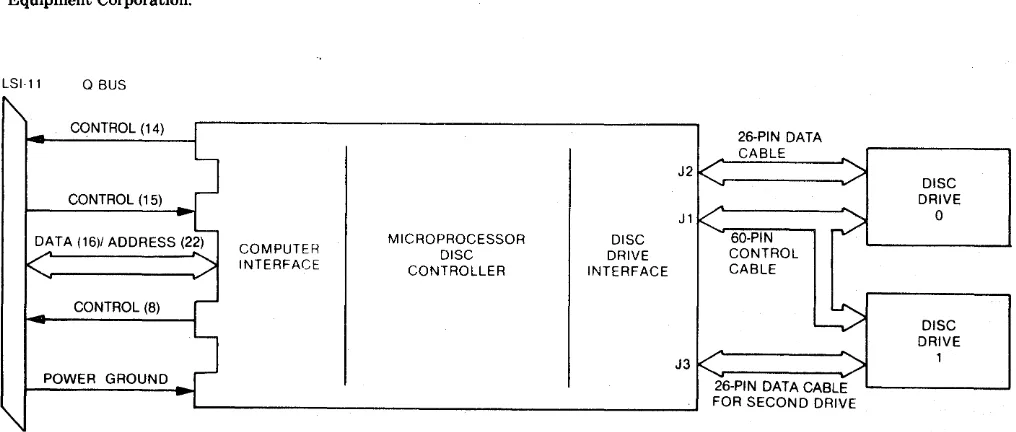
[image:8.615.66.574.494.710.2]Data transfers are directly to and from the com-puter memory using the DMA facility of the LSI-II I/O bus. In addition, the controller monitors the status of the disc units and the data being trans-ferred and presents this information to the com-puter upon request. An error correction code with a 56-bit checkword corrects error bursts up to 11 bits. To compensate for media errors, bad sectors are skipped and alternates assigned, and there is an automatic retry feature for read errors. The con-troller is capable of addressing four megabytes and controlling up to two disc drives in various config-urations up to a total on-line formatted capacity of 220.32 megabytes. Figure 1-1 is a simplified diagram of a disc system.
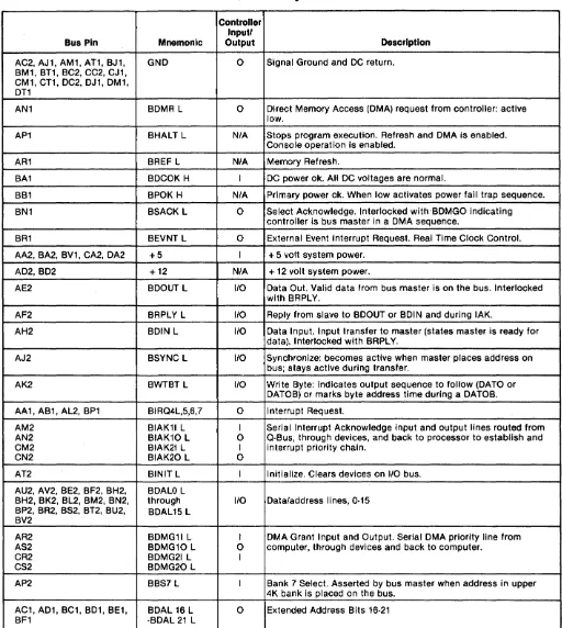
LSI-II Q BUS INTERFACE
Commands, data and status transfers between the controller and the computer are executed via the parallel 110 bus (Q bus) of the computer. Data
[image:9.617.39.551.162.734.2]trans-fers are direct to memory via the DMA facility of the Q bus; commands and status are under pro-grammed 1/0. Controller/Q bus interface lines are listed in Table I-I.
Table I-I. Controller/Q-Bus Interface Lines
Controller Inputl
Bus Pin Mnemonic Output Description
AC2, AJ1, AM1, AT1, BJ1, GND 0 Signal Ground and DC return. BM1, BT1, BC2, CC2, CJ1,
CM1,
cn,
DC2, DJ1, DM1, DT1AN1 BDMR L 0 Direct Memory Access (DMA) request from controller: active low.
AP1 BHALT L N/A Stops program execution. Refresh and DMA is enabled. Console operation is enabled.
AR1 BREF L N/A Memory Refresh.
BA1 BDCOK H I DC power ok. All DC voltages are normal.
BB1 BPOK H N/A Primary power ok. When low activates power fail trap sequence.
BN1 BSACK L 0 Select Acknowledge. Interlocked with 'BDMGO indicating controller is bus master in a DMA sequence.
BR1 BEVNT L 0 External Event Interrupt Request. Real Time Clock Control.
AA2,BA2, BV1,CA2, DA2 +5 I + 5 volt system power.
AD2, BD2 +12 N/A + 12 volt system power.
AE2 BDOUT L 110 Data Out. Valid data from bus master is on the bus. Interlocked with BRPLY.
AF2 BRPLY L 110 Reply from slave to BDOUT or BDIN and during IAK.
AH2 BDIN L 110 Data Input. Input transfer to master (states master is ready for data). Interlocked with BRPLY.
AJ2 BSYNC L 110 Synchronize: becomes active when master places address on bus; stays active during transfer.
AK2 BWTBT L 110 Write Byte: indicates output sequence to follow (DATO or DATOB) or marks byte address time during a DATOB.
AA1, AB1, AL2, BP1 BIRQ4L,5,6,7 0 Interrupt Request.
AM2 BIAK11 L I Serial Interrupt Acknowledge input and output lines routed from AN2 BIAK10 L 0 Q·Bus, through devices, and back to processor to establish and CM2 BIAK21 L I interrupt priority chain.
CN2 BIAK20 L 0
AT2 BINIT L I Initialize. Clears devices on 110 bus.
AU2, AV2, BE2, BF2, BH2, BDALO L
BH2, BK2, BL2, BM2, BN2, through 110 Data/address lines, 0·15 BP2, BR~ BS~ BT~ BU~ BDAL15 L
BV2
AR2 BDMG11 L I DMA Grant Input and Output. Serial DMA priority line from AS2 BDMG10 L 0 comp~ter, through devices and back to computer.
CR2 BDMG21 L I
CS2 BDMG20 L
AP2 BBS7 L I Bank 7 Select. Asserted by bus master when address in upper 4K bank is placed on the bus.
INTERRUPT
The interrupt vector address i~t factory set to address 210 (alternate 254). The vector address is programmed in a PROM on the controller, allowing user selection.
Interrupt requests are generated under the follow-ing conditions:
1. When the Controller Ready bit is set upon completion of a command.
2. When any drive sets an associated Attention Flag in the Attention Register and the Con-troller Ready bit is se,t.
3. When the controller or any drive indicates the presence of an error by setting the combined Error/Reset bit in the Control and Status Register.
4. When the Controller Ready bit is set by con-ventional initialization upon completion of a controller command or when an error condi-tion is detected. For test purposes, a forced interrupt may be generated by the Controller Ready and Interrupt Enable bits.
DISC INTERFACE
The controller interfaces one or two disc drives through So- and 2S-pin cables. If two drives are used, the SO-pin control cable ("A" cable) is daisy chained to drive 0 and 1. The 2S-pin cables ("B" cable) are connected separately from the controller to each drive. The maximum length of the SO-pin cable is 100 feet. The maximum length of the 2S-pin cable is 50 feet. Table 1-2 lists the SO-pin interface signals, and Table 1-3 lists the 2S-pin interface signals.
OPERATING SYSTEM COMPATIBILITY
RT-ll: The emulation is transparent to the RT-ll version 4.0 operating system, using the standard device handler supplied by DEC.
RSX-ll: The emulation is transparent to the RXS-ll version 4.0 operating system, using the standard device handler supplied by DEC.
RSTS: The emulation is transparent to the RSTS version 7.2 operating system, using the standard device handler supplied by DEC.
Table
1-2.
Controller To Drive 1/0 Interface-"A" CablePin Polarity Signal Name (Active)
(DILOG Term)
-
+ Source [image:10.612.187.567.37.765.2]DEVICE' SELECT 0 (USELO) 23 53 Controller DEVICE SELECT 1 (USEL 1) 24 54 Controller DEVICE SELECT 2 (USEL2) 26 56 Controller DEVICE SELECT 3 (USEL3) 27 57 Controller SELECT ENABLE (USTAG) 22 52 Controller SET CYLINDER TAG (TAG1) 1 31 Controller SET HEAD TAG (TAG2) 2 32 Controller CONTROL SELECT (TAG3) 3 33 Controller BUS OUT 0 (BITO) 4 34 Controller BUS OUT 1 (BIT1) 5 35 Controller BUS OUT 2 (BIT2) 6 36 Controller BUS OUT 3 (BIT3) 7 37 Controller BUS OUT 4 (BIT 4) 8 38 Controller BUS OUT 5 (BIT5) 9 39 Controller BUS OUT 6 (BIT6) 10 40 Controller BUS OUT 7 (BIT7) 11 41 Controller BUS OUT 8 (BIT8) 12 42 Controller BUS OUT 9 (BIT9) 13 43 Controller BUS OUT 10 (BlnO) 30 60 Controller DEVICE ENABLE (OCD) 14 44 Controller INDEX (INDEX) 18 48 Drive SECTOR MARK (SEC) 25 55 Drive FAULT (FAULT) 15 45 Drive SEEK ERROR (SERR) . 16 46 Drive ON CYLINDER (ONCYL) 17 . 47 Drive UNIT READY (UN ROY) 19 49 Drive WRITE PROTECTED (WPRT) 28 58 Drive ADDRESS MARK (AMF) 20 50 Drive BUS·DUAL·PORT ONLY 21 51 Drive SEQUENCE IN (PICK) 29 Controller HOLD (HOLD) 59 Controller
Table 1-3. Controller To Drive 1/0 Interface-"8" Cable
Pin Polarity Signal (Active)
(DILOG Term)
-
+ Ground SourceGround 1
Servo Clock (SCLOCK) 2 14 Drive
Ground 15
Read Data (RDATA) 3 16 Drive
Ground 4
Read Clock (RCLOCK) 5 17 Drive
Ground 18
Write Clock (WCLOCK) 6 19 Controller
Ground 7
Write Data (WDATA) 8 20 Controller
Ground 21
Unit Selected (USEL) 22 9 Drive Seek End (SEEK) 10 23 Drive
Ground 11
Reserved for Index 12 24
Ground 25
[image:10.612.323.574.58.492.2]CONTROLLER SPECIFICATIONS·
Mechanical-The Model DQ215 is completely con-tained on one quad module 10.44 inches wide by 8.88 inches deep, and plugs into and requires one slot in any DEC LSI-II based backplane.
Computer I/O
Register Addresses (PROM selectable) -Control/Status Register 1 (RKCSl) 777 440 - Word Count Register (RKWC) 777 442 -Bus Address Register (RKBA) 777 444 -Disc Address Register (RKDA) 777-446 -Control/Status Register 2 (RKCS2) 777 450 -Drive Status Register (RKDS) 777 452 -Error Register (RKER) 777 454
-Attention Summary/Offset Register (RKAS/ OF) 777 456
-Desired Cylinder Register (RKDC) 777 460 -Extended Memory Address Register (RKXMA)
777 462
-Data Buffer Register (RKDB) 777 464 -Maintenance Register 1 (RKMRl) 777 466 -ECC Position Register (RKECPS) 777 470 -ECC Pattern Register (RKECPT) 777 472 - Maintenance Register 2 (RKMR2) 777 474 -Maintenance Register 3 (RKMR3) 777 476 -Enable Real Time Clock Control (RKERTC)
777 546
Data Transfer -Method: DMA
- Maximum block size transferred in a single operation is 64K words.
Bus Load
-1 std unit load
Address Ranges .. ~
- Disc drive: up to 220.32 megabytes -Computer Memory: to 2 megawords
Interrupt Vector Address
-PROM selectable, factory set a~ 210 (alternate 254) priority level BR5
Disc Drive I/O
Connector-one 60-pin type "A" flat ribbon cable mounted on outer edge of controller module Two 26-pin type "B" ribbon cables (1 for each drive
inter-faced with). ..
Signal-SMD A/B flat cable compatible
Power-+5' 'Volts at 3.5 amps, +12 volts at 300 mil-liamps from computer power supply.
Environment-Operating temperature 40°F. to 140°F., humidity 10 to 95,% non-condensing.
Shipping Weight-5 pounds, includes documenta-tion and cables.
SECTION 2
INSTALLATION
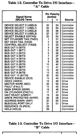
INSPECTION
The padded shipping carton that contains the con-. troller board also contains an instruction manual
and cables to the first disc drive if this option is exercised. The controller is completely contained on the quad-size printed circuit board. Disc drives, if supplied, are contained in a separate shipping carton. Inspect the controller and cables for damage.
PIN 1
~
r1
n
CAUTION
If damage to any of the components is noted, do not install. Immediately inform the carrier and DILOG .
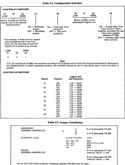
Installation instructions for the disc drive are con-tained in the disc drive manual. Before installing any components of the disc system, read Sections 1, 2 and 3 of this manual. Figure 2-1 illustrates the con-figuration of the controller. Tables 2-1 and 2-2 describe switch and jumper settings.
J2
J3
C23
S1D
017 S8
S1D
019 E23pe K
JP
S9 Re
-0
-C•
0- -A
• 3 E16
-e
•
• 2
•
• 1
r1
r
[image:12.615.57.573.144.756.2]Table 2-1. Configuration Switches
LOCATION D17 SWITCHES
Sl (LSB)
\
52
T
S3 (M5B)
,
Binary Number of the first logical unit of the second
physical drive.·
54
ON = Bootstrap enable OFF = Bootstrap
disable
• For example, if there are four logical units (numbered 0-3) in the first drive, set the switches for the fifth logical unit (number 4) as follows:
(LSB) 51 52
o
0(M5B) S3
55
ON = Controller error correction OFF = CPU error
correction
Note
86 (L5B
,
57 y (M5B), 58 Binary number of last addressable logical unit.59
ON = Enable Real Time Clock Control. When enabled, emulates the real
time clock register, address 777 546 OFF= Disables Real Time
Clock Control.
If S1, S2, and S3 are off (000), the control/er will default to aI/logical units on the first physical drive (drive 0). Because of the characteristics of some operating systems, the switches should be set for two drives even if only one drive is present.
LOCATION C23 SWITCHES
Logical Unit Switch Position and Emulation
[image:13.620.37.547.70.313.2]51 ON LUO
=
RK07 OFF LUO=
RK06 52 ON LU1=
RK07 OFF LU1 = RK06 S3 ON LU2=
RK07 OFF LU2=
RK06 S4 ON LU3 = RK07 OFF LU3 = RK06 55 ON LU4=
RK07 OFF LU4=
RK06 56 ON LU5 = RK07 OFF LU5=
RK06 57 ON LU6=
RK07 OFF LU6=
RK06 58 ON LU7=
RK07 OFF LU7=
RK06Table 2-2. Jumper Installation
BOOTSTRAP
ADDRES5 JUMPERS E16
INTERRUPT LEVEL
DEVICE
ADDRE55 JUMPERS 019
D. .C .A
.B
Jumper Installed JP1, JP2, JP3 JP2, JP3 JP1, JP3 JP1
• A to B (standard) 773 000
A to C (alternate) 775 000
Level BR4
BR5 (Factory Set) BR6
BR7
R to K (standard) 777 440 Interrupt Vector = 210
R to P (alternate) 776 700 Interrupt Vector = 254
PRE-INSTALLATION CHECKS
There are various LSI -II configurations, many of which were installed before DEC made a hard disc available for LSI-II based systems. Certain config-urations require minor modifications before operat-ing the disc system. These modifications are as follows:
A. If the system contains a REV11-C module, it must be placed closer to the processor module (higher priority) than the controller if the DMA refresh logic on the REV11-C is enabled.
B. If the 4K memory on the DK11-F is not used and the memory in the system does not re-quire external refresh, the DMA refresh logic on the REV11-C should be disabled by remov-ing jumper W2 on the REV11-C module. C. If the system contains a REV11-A module,
the refresh DMA logic must be disabled since the module must be placed at the end of the bus (REV11-A contains bus terminator). D. If the REV11-C module is installed, cut the
etch to pin 12 on circuit D30 (top of board) and add a jumper between pin 12 and pin 13 of D30.
E. If the system requires more than one back-plane, place the REV-II terminator in the last available location in the last backplane.
INSTALLATION
To install the controller module, proceed as follows:
CAUTION
Remove DC power from mounting assembly before inserting or removing the controller module.
Damage to the backplane assembly may occur if the controller module is plugged in backwards.
1. Select the backplane location into which the controller is to be inserted. Be sure that the disc controller is the lowest priority DMA device in the computer except if the DMA refresh/bootstrap ROM option module is in-stalled in the system. The lowest priority device is the device farthest from the proces-sor module. Note that the controller contains a bootstrap ROM.
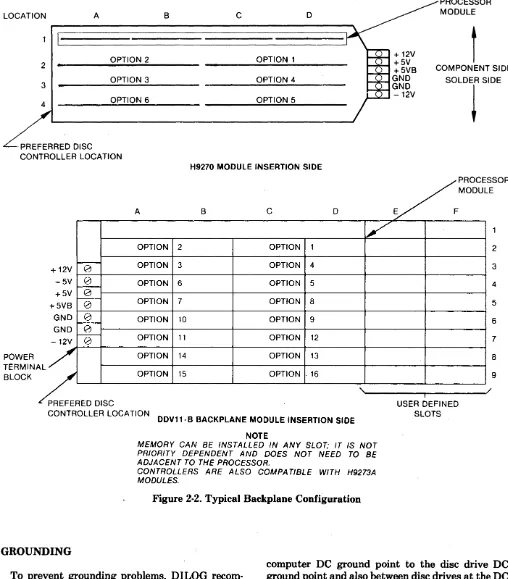
There are several backplane assemblies available from DEC and other manufactur-ers. Figure 2-2 shows typical backplane con-figurations. Note that the processor module is always installed in the first location of the backplane or in the first location in the first backplane of multiple backplane systems.
I t is important that all option slots between the processor and the disc controller be filled to ensure that the daisy-chained interrupt (BIAK) and DMA (BDMG) signal be com-plete to the controller slots. If there must be empty slots between the controller and any option board, the following backplane jumpers must be installed:
FROM TO SIGNAL
CO x NS CO x M2 BIAK1/l0
CO x S2 CO x R2 BDMG1/LO
t
Last Full Controller
t
Option Slot Slot
2. Insert the controller into the selected back-plane position .. Be sure the controller is in-stalled with the components facing row one, the processor.
The controller module is equipped with handles on the side opposite the slot tors. Gently position the module slot connec-tors into the backplane then press until the module connectors are firmly seated into the backplane. Both handles must be pressed simultaneously. When removing the module, apply equal pulling pressure to both ha~l(iles. 3. Feed the module connector end of the disc I/O cables into the controller module connectors. Ensure pin 1 is matched with the triangle on the connector as shown in Figure 281. Install
the cable connectors into the module con-nectors. Verify that the connectors are firmly seated.
4. Connect the disc-end of the I/O cables to the disc I/O connectors. Be sure that the bus terminator is installed at the last disc in the system.
5. Refer to the disc manual for operating in-structions and apply power to the disc and computer.
6. Observe that the green DIAGnostic LED on the controller board is lit.
LOCATION A B C 0
2 OPTION 2 OPTION 1
3 OPTION 3 OPTION 4
4 OPTION 6 OPTION 5
. PREFERRED DISC CONTROLLER LOCATION
POWER TERMINA BLOCK
H9270 MODULE INSERTION SIDE
A B C 0
[7
OPTION 2 OPTION 1
~ OPTION 3 OPTION 4
+12V 0
-5V 0 OPTION 6 OPTION 5
+5V
g
+5VB ~- OPTION 7 OPTION 8
GND ~---0 OPTION 10 OPTION 9
GND ~
-12V 0 OPTION 11 OPTION 12
L /
OPTION 14 OPTION 13
OPTION 15 OPTION .16
"
PREFERED DISCCONTROLLER LOCATION
DDV11· B BACKPLANE MODULE INSERTION SIDE
NOTE
MEMORY CAN BE INSTALLED IN ANY SLOT; IT IS NOT PRIORITY DEPENDENT AND DOES NOT NEED TO BE ADJACENT TO THE PROCESSOR.
[image:15.620.44.552.61.640.2]CONTROLLERS ARE ALSO COMPA TlBLE WITH H9273A MODULES.
Figure 2·2. Typical Backplane Configuration
GROUNDING
PROCESSOR MODULE
t
COMPONENT SIDE SOLDER SIDE
~
PROCESSOR
E
/MODUL
E F
i USER DEFINED
SLOTS
/ 2
3
4
5
6
7
8
9
To prevent grounding problems, DILOG recom-mends standard ground braid be installed from the
SECTION 3
OPERATION
INTRODUCTION
This section contains procedures for operating the computer system with the controller and a disc drive or drives. An understanding of DEC operating procedures is assumed. The material here is pro-vided for' 'first time users" of disc subsystems and describes procedures for bootstrapping, formatting, and diagnostic testing.
The programs supplied with each controller are on floppy disc or magnetic tape media, depending on what is specified on the sales order. If the user is not able to run floppy disc or magnetic tape media, an EPROM program may be used for some subsystems to format the disc. Instructions and constraints for the EPROM program are described at the end of this section.
PRECAUTIONS AND PREOPERATIONAL CHECKS
The following precautions should be observed while operating the system. Failure to observe these precautions could damage the controller, the disc cartridge, the computer, or could erase a portion or all of the stored software.
1. If the controller bootstrap is to be used, set controller switch S4 on, and disable other bootstraps that reside at that address. 2. See Figure 2-1 for proper positions of the
switches and jumpers. See Tables 2-1 and 2-2 for switch and jumper settings.
3. Do not remove or replace the controller board with power applied to the computer.
4. If system does not operate properly, check operating procedures and verify that the items in Section 2 have been performed.
Before operation the following checks should be made:
1. Verify that the controller board is firmly seated in backplane connector.
2. Verify that the cables between the controller and the disc drive are installed.
3. Be sure the disc drive cartridge is installed (if it is to be used).
4. Apply power to the computer and the console device.
5. Verify that green DIAG light on front edge of the controller board lights.
6. Be sure power is applied to disc drive and READY light is on.
BOOTSTRAP PROCEDURE
The following assumes the system is in· ODT mode. Note that the bootstrap can be used under processor Power Up Mode 2 conditions. Refer to the appropriate DEC manual for a discussion of the Power Up Modes. Further note that the disc drive does not need to be READY to enter the bootstrap. Reset the system by pressing RESET or enter the following (characters underlined are output by the system; characters not underlined are input by the operator):
@ 773000G or 775000G
Depends on jumper configuration above.
*
Enter one of the following: DMO, DPO, DLO, DRO, MSO, MTO, DYO or FT <CR>.Definitions are as follows:
DM
=
RK06/07 Disc DP = RP02/03 Disc DL=
RLOl102 Disc DR = RM02/03 Disc MS=
TSII Tape MT=
TapeDY = RX02 Floppy Disc FT
=
EPROM Formatter.FORMAT AND DIAGNOSTIC TEST PROGRAM
Description
DILOG's Universal Firmware and Diagnostic Program permits the user to format a disc pack for his particular application; compensate for media errors; and test the controller and drive. When for-matted, the disc may be partitioned horizontally or vertically. Either way the pack is divided into logical units which the computer recognizes. The user may select one of three types of partitioning:
I-head, 2-head or vertical.
The constraints for selecting each are:
Subsystem:
• Maximum number of logical units is 8.
I-head:
• Maximum number of heads (surfaces) is 8. • Maximum size of logical units is 270,336
records. 2-head:
• Maximum number of heads (surfaces) is 16. • Number of fixed and removable heads
(sur-faces) must be even.
• Maximum size of logical units is 270,336 records.
Vertical:
• Maximum size of logical units is 270,336 records.
Drive types CMD or DFR are formatted for a I-head partition. SMD or MMD types are usually formatted vertically.
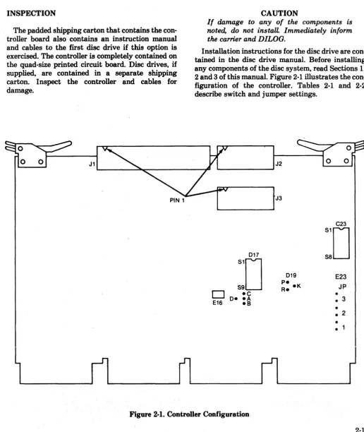
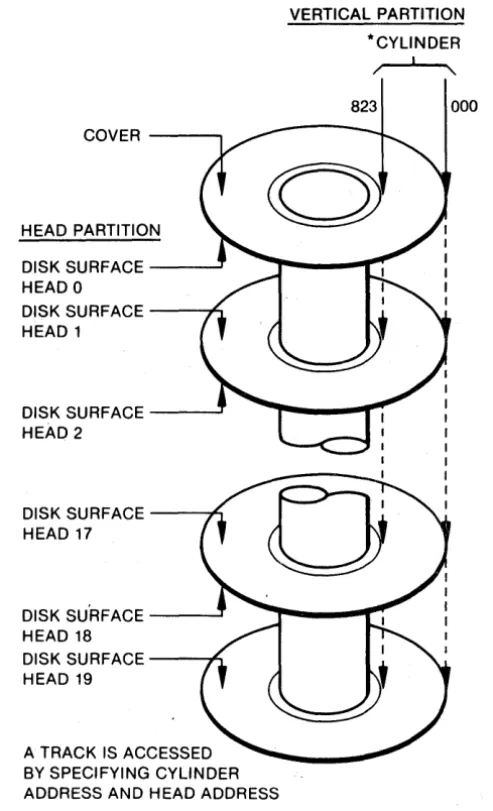
The disc pack is divided vertically by cylinders and horizontally by heads (or data surfaces). Each head (surface) is further divided into tracks. A track is addressed by cylinder number and head number. Tracks are further divided into sectors (or records or blocks) which the computer recognizes as incre-ments within a logical unit. Sectors consist of over-head bytes (such as address, sync, error correction) and data bytes. The standard number of data bytes, bytes usable by the computer, is 512 data bytes per sector. Figure 3-1 illustrates vertical and head partitioning.
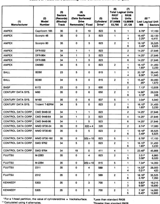
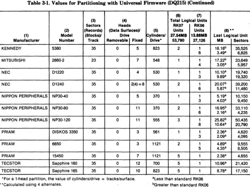
Table 3-1 is a partial list of disc drives and specifi-cations for partitioning. Column 1 lists the manu-facturer. Column 2 lists the model number. Column 3 lists the number of sectors (also called records and blocks) per track. Column 4 lists the number of heads (also called data surfaces) per drive. Column 5 lists the number of cylinders per drive. Columns 6
COVER - - - ,
HEAD PARTITION
DISK SURFACE _ _ - - J
HEADO
DISK SURFACE - - - M
HEAD 1
DISK SURFACE _ _ - - J
HEAD 2
DISK SURFACE --~
HEAD 17
DISK SU'RFACE _ _ - - J
HEAD 18
DISK SURFACE - - - . n
HEAD 19
A TRACK IS ACCESSED BY SPECIFYING CYLINDER ADDRESS AND HEAD ADDRESS
VERTICAL PARTITION
*CYLINDER
/ \.
823 000
[image:17.618.303.550.62.468.2]*NUMBER OF CYLINDERS AND HEADS VARIES WITH TYPE OF DRIVE
Figure 3-1. Partitions
and 7 list the emulations, the number of megabytes per logical unit, and the number of sectors per logical unit. Column 8 lists the· megabyte capacity and number of sectors of the last logical unit
par-titioned. For CMD drives (Note c), the value listed is 'for all logical units as well as the last.
Table 3·1. Values for Partitioning with Universal Firmware (DQ215)
(6) (7) (3) (4) Total Logical Units Sectors Heads RK07 RK06 (2) (Records) (Data Surfaces)' (5) Units Units (1) Model (Blocks)' Drive Cylinders' 27.54MB 13.88MB Manufacturer Number Track Removable Fixed Drlve* 53,790 27,126
AMPEX Capricorn 165 35 0 10 823 5 1
AMPEX Scorpio 48 35 0 3 823 1 1 4
AMPEX Scorpio 80 35 0 5 823 2 1 6
AMPEX DFR-932 34 1 1 823 2
AMPEX DFR-964 34 1 3 823 4
AMPEX DFR-996 34 1 5 823 6
AMPEX DM980 34 5 0 823 2 1
6
BALL BD50 23 5 0 815 1 1
4
BALL BD80 34 5 0 815 2 1
6
BASF 6172 23 0 3 600 2
CENTURY DATA SYS. M80 35 0 6 650 2 1 6
CENTURY DATA SYS. M160 35 0 6 837 5 1
CENTURY DATA SYS. Trident T-82RM 34 5 0 823 2 1 6
CONTROL OAT A CORP. CMD 9448-32 34 1 1 823 2
CONTROL OAT A CORP. CMD 9448-64 34 1 3 823 4
CONTROL DATA CORP. CMD 9448-96 34 1 5 923 6
CONTROL DATA CORP. MMD 9730-24 35 0 2(2)= 4 320 2
CONTROL DATA CORP. MMD 9730-80 35 0 5 823 2 1 6
CONTROL DATA CORP. MMD 9730-160 35 0 2(5) = 10 823 5 1
CONTROL DATA CORP. SMD 9762 34 5 0 823 2 1 6
CONTROL DATA CORP. SMD 9764 34 19 0 411 4 1
FUJITSU M-2283 35 0 4 823 2 1
5
FUJITSU M-2284 35 0 2(5) = 10 815 5 1
FUJITSU 2311 35 0 4 589 1 1
4
FUJITSU 2312 35 0 7 589 2 1
6
KENNEDY 5303 35 0 3 700 1 1
3
KENNEDY 5305 35 0 5 700 2 1
5
• For a 1-head partition, the value of cylinders/drive = tracks/surface. aLess than standard RK06
bGreater than standard RK06 cCMO
• ·Calculated using 4 alternates.
(8)** Last Log ical Unit
MB Sectors
8.788 17,150
16.45b 32,130 2.258 4,410
18.18b 35,525 3.498 6,825
14.25c 27,846 14.25c 27,846 14.25c 27,846 16.10b 31,450 1.658 3,230
20.19b 39,445 6.068 11,845
15.40b 30,090 .958 1,870
7.138 13,938
14.86b 29,028
0.1~ 246
3.048 5,940
16.10b 31,450 1.658 3,230
14.25c 27,846 14.25c 27,846 14.25c 27,846 8.748 17,080
18.18b 35,525 3.498 6,825
8.788 17,150
16.10b 31,450 1.658 3,230
23.48b 45,866
3.518 6,860 3.088 6,020
7.348 14,350
14.33b 28,000 0.218 420
18.18b 35,525 3.768 7,350
9.838 19,215 9.568 18,690
Table 3-1. Values for Partitioning with Universal Firmware (DQ215) (Continued)
(6) (7)
(3) (4) Total Logical Units Sectors Heads RK07 RK06
(2) (Records) (Data Surfaces)1 (5) Units Units (8) **
(1) Model (Blocks)1 Drive Cylinders! 27.S4MB 13.88MB Last Log Ical Unit Manufacturer Number Track Removable Fixed Drlve* 53,790 27,126 MB Sectors
KENNEDY 5380 35 0 5 823 2 1 18.18b 35,525 6 3.49a 6,825
MITSUBISHI 2860-2 23, 0 7 548 ' 1 1 17.22b 33,649 4 3.05a 5,957
NEC 01220 35 0 4 530 1 1 10.10a 19,740 3 9.89a 19,320
NEC 01240 35 0 2(4)=8 530 2 1 20.07b 39,200 6 5.87a 11,480
NIPPON PERIPHERALS NP30-40 35 0 5 370 1 1 5.19a 10,150 3 4.03a 9,450
NIPPON PERIPHERALS NP30-80 35 0 11 370 2 1 16.95b 33,110 6 2.16a 4,235
NIPPON PERIPHERALS NP30-120 35 0 11 555 3 1 25.82b 50,435 8 10.64a 20,790
PRIAM OISKOS 3350 35 0 3 561 1 1 2.36a 4,620 3 2.09a 4,095
PRIAM 6650 35 0 3 1121 2 1 4.89a 9,555 5 4.35a 8,505
PRIAM 15450 35 0 7 1121 5 1 2.38a 4,655
TECSTOR Sapphire 160 35 0 12 700 5 1 10.96a 21,420
TECSTOR Sapphire 165 35 0 10 823 5 1 8.78a 17,150
·For a i-head partition, the value of cylinders/drive = tracks/surface. aLess than standard RK06 bGreater than standard RK06 cCMO
• ·Calculated using 4 alternates.
whether the last unit is an expanded or a partial unit.
The values in the table are calculated for the most efficient use of the drive; that is, total formatting capacity of the drive with a standard number of spare cylinders. The user may require another type of partitioning for a particular application, in which case the program will prompt and calculate for that application.
Parameters for disc drives not listed in Table 3-1 may be determined from manufacturer's specifica-tions and the following: Determine the number of bytes per track from the manufacturer's specifica-tion. The number of bytes per sector (data and over-head) for DILOG controllers is 576. Divide the num-ber of bytes per track by the numnum-ber of bytes per sector. Drop the remainder. This value is the number of sectors per track. Then, number of sectors per track X number of heads X number of cylinders per drive
=
number of sectors per drive.The user may require alternate cylinders, or spares, to compensate for media flaws, soft errors, or marginal drive conditions. The values in the table
provide for four alternate cylinders. All three types of partitioning in the program make provisions for sparing. The program accounts for alternates when calculating the number and size of logical units.
If the number of logical units is to be changed, the configuration switches, shown in Figure 2-1, should also be changed after completion of format and test. The descriptions below indicate what parameters will be changed as various elements are changed; for example, if the number of logical units is changed, the size of the logical units will change.
I-Head Partition
A I-head partition is used for CMD drives. The column numbers below refer to Table 3-1. Param-eters are developed as follows:
2. Determine the number of alternate tracks (cylinders) per drive. The standard number of alternates is four.
3. Subtract the number of alternates from the tracks per surface.
4. The number of heads corresponds to the number of logical units.
5. Then, sectors per track X heads per drive X (tracks per surface minus alternates) -sectors per drive.
6. Sectors per drive X 512
=
byte capacity.For example, an AMPEX DFR-932 has 34 sectors per track, 2 heads per drive and 823 tracks/surface. If 4 alternates are required, then:
34 X 2 X (823 - 4) = 55,692 sectors/drive
Because there are two heads, there are two logical units.
and
55,692 = 27,846 sectors/logical unit
2
27,846 X 512
=
14.25 megabytes/logical unit2-Head Partition
The parameters for 2-head partitioning are the same as for I-head except the number of sectors/ logical unit is multiplied by 2:
1. Determine the number of sectors per track (Column 3), heads per drive (Column 4), and tracks per surface (Cylinders per Drive, Column 5).
2. Determine the number of alternate tracks (cylinders) per drive. The standard number of alternates is four.
3. Subtract the number of alternates from the tracks per surface.
4. Then, sectors per track X heads per drive X (tracks per surface minus alternates)
=
sectors per, drive.5. Sectors per drive X 512
=
byte capacity.For example, a CDC 9730-24 has 35 sectors per track, 4 heads per drive and 320 tracks per surface. If 4 alternates are required, then:
35 X 4 X (320-4) = 44,240 sectors/driv~
Because there are four heads, and two heads com-prise one logical unit, there are two logical units.
44,240
=
22,120 sectors/logical unit2
and
22,120 X 512
=
11.32 megabytes/logical unitVertical Partition
With vertical partitioning, the user may select the number of logical units or the size of the logical unit. If the number of logical units is selected, the logical units will be of equal size. If the size of the logical units is selected, all logical units may not be of equal . size. For example there may be 2 equal RK07 logical units of 53,790 sectors/logical unit and a partial RK06 logical unit of 31,450 sectors/logical unit.
Parameters for vertical partitioning are deter-mined as follows:
The user specifies the number of logical units (all logical units are of equal size):
1. Determine the required number of alternate cylinders per drive. Subtract the number of alternates from the number of cylinders per drive (Column 5). This value is the usable cyl-inders per drive.
2. Determine the number of logical units per drive required. Then,
3. Number of usable cylinders per drive divided by number of logial units required
=
Number of cylinders per logical unit. The remainder is assigned as alternate.4. Number of cylinders per logical unit X
sectors per track X number of heads = Number of sectors per logical unit.
5. Number of sectors per logical unit X 512 =
Megabyte capacity per logical unit.
For example, if the user has a Century Data drive, Model T-82RM and 4 alternates (standard) and 3 logical units are required, then
and
823 - 4
=
819 usable cylinders819 = 273
3
Then,
273 X 34 X 5
=
46,410 sectors per logical unit and46,410 X 512 = 23.76 Mbytes per logical unit
The user specifies the size of logical units in sectors per logical unit (the last logical unit will be a different size).
1. Determine the required number of alternate cylinders per drive. Subtract the number of alternates from the number of cylinders per drive (Column 5). This value is the usable cylinders per drive.
2. Determine the required number of sectors (blocks) per logical unit. Then,
3. Sectors per track (Column 3) X number of heads (Column 4) divided into sectors per log-ical unit = cylinders per logical unit. If there is a remainder, the number of cylinders per logical unit is rounded off to the next higher number.
4. Number of usable cylinders divided by cylinders per logical unit
=
number of logical units. If there is a remainder, the number of logical units is rounded off to the next higher number.5. Number of cylinders per logical unit X
number of full (equal size) logical units
=
Number of cylinders full (equal size) logical units.6. Number of usable cylinders per. drive minus number of cylinders in full logical units
=
Number of cylinders in partial logical unit.For example, if the user has a Century Data drive, Model T-82RM, and 4 alternates and 53,790 sectors per logical unit (standard RK07) are required, then
and
823 - 4
=
819 usable cylinders53,790 = 316.41 34 X 5
which becomes
317 cylinders per logical unit then,
819
=
2.58 logical units per drive 317or 2 RK07 units and 1 partial RK06 unit.
For the partial logical unit,
317 X 2
=
634819 - 634
=
185 cylinders per partial logical unitSectors per the partial unit are calculated as follows:
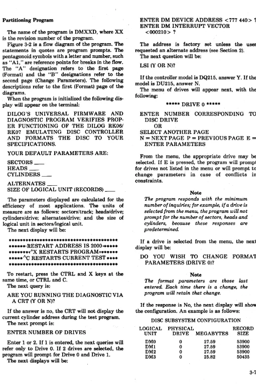
Partitioning Program
[image:22.618.63.573.15.792.2]The name of the program is DMXXD, where XX is the revision number of the program.
Figure 3-2 is a flow diagram of the program. The statements in quotes are program prompts. The pentagonoid symbols with a letter and number, such as "AI," are reference points for breaks in the flow. The "A" designation refers to the first page (Format) and the "B" designations refer to the second page (Change Parameters). The following descriptions refer to the first (Format) page of the diagrams.
When the program is initialized the following dis-play will appear on the terminal:
DILOG'S UNIVERSAL FIRMWARE AND DIAGNOSTIC PROGRAM VERIFIES PROP-ER FUNCTIONING OF THE DILOG RK06/ RK07 EMULATING DISC CONTROLLER AND FORMATS THE DISC TO YOUR SPECIFICATIONS.
YOUR DEFAULT PARAMETERS ARE: SECTORS_
HEADS_ CYLINDERS_ ALTERNATES _
SIZE OF LOGICAL UNIT (RECORDS)_
The parameters displayed are calculated for the efficiency of most applications. The units of measure are as follows: sectors/track; heads/drive; cylinders/drive; alternates/drive; and the size of logical unit in sectors/logical unit.
The next display will be:
*************************************** ******: RESTART ADDRESS IS 20001***** *******II"·X RESTARTS PROGRAM~******
***** I\C RESTARTS CURRENT TEST **** *************************************** To restart, press the CTRL and X keys. at the same time, or CTRL and C.
The next query is:
ARE YOU RUNNING THE DIAGNOSTIC VIA A CRT (Y OR N)?
If the answer is no, the CRT will not display the current cylinder address during the test program.
The next prompt is:
ENTER NUMBER OF DRIVES
Enter 1 or 2. If 1 is entered, the next queries will refer only to Drive
o.
If 2 drives are selected, the program will prompt for Drive 0 and Drive 1.The next displays will be:
ENTER DM DEVICE ADDRESS <777440> ? ENTER DM INTERRUPT VECTOR
<000210> ?
The address is factory set unless the user requested an alternate address (see Section 2).
The next question will be: LSI (Y OR N)?
If the controller model is DQ215, answer Y. If the model is DU215, answer N.
The menu of drives will appear next, with the following:
***** DRIVE 0 *****
ENTER NUMBER CORRESPONDING TO DISC DRIVE
OR
SELECT ANOTHER PAGE
N = NEXT PAGE P = PREVIOUS PAGE E = ENTER PARAMETERS
From the menu, the appropriate drive may be selected. If E is pressed, the program will prompt for drives not listed in the menu or will prompt to change parameters in case of conflicts in constraints.
Note
The program responds with the minimum number of inquiries; for example, if a drive is selected from the menu, the program will not prompt for the number of sectors, heads and cylinders, because these responses are predetermined.
If a drive is selected from the menu, the next display' will be:
DO YOU WISH TO CHANGE FORMAT PARAMETERS (DRIVE O)?
Note
The format parameters are those last entered. Each time there isa change, the program will retain that change.
If the response is No, the next display will show the configuration. An example is as follows:
DISC SUBSYSTEM CONFIGURATION
LOGICAL PHYSICAL RECORD
UNIT DRIVE MEGABYTES SIZE
SET HARDCOPY
SWITCH
SET FOR 2 DRIVES
"ENTER DEVICE ADDRESS OR RETURN FOR DEFAULT"
"ENTER INTER-RUPT VECTOR OR RETURN FOR DEFAULT"
SET LSI SWITCH
SET CRT SWITCH
SET FOR 1 DRIVE
SET PDP SWITCH
. *TO OR FROM OPPOSITE PAGE
DISPLAY MENU
SET MENU SWITCH
GET PARAMETERS FOR SELECTED
DRIVE
GO TO CHANGE PARAMETERS
N
DISPLAY SUBSYSTEM CONFIGURATION
Figure 3-2(A). Universal Formatting
CLEAR MENU SWITCH
SET FIXED MEDIA SWITCH
BEGIN TEST
[image:23.624.45.563.43.757.2]ENTER NEW VALUE
ENTER NEW VALUE
ENTER NEW VALUE
ENTER NEW VALUE
ENTER NEW PARTITION
"ENTER 1) RK06 2) RK07"
ENTER NEW VALUE
ENTER NEW VALUE
DISPLA Y EXTRA CYLINDER MESSAGE
AND COLLECT OPERATOR RESPONSE
°TO OR FROM OPPOSITE PAGE
[image:24.613.57.551.36.737.2]DM4 1 27.59 53900
DM5 1 27.59 53900
DM6 1 27.59 53900
DM7 1 25.82 50435
PHYSICAL DRIVE 0 HAS 44 ALTERNATE TRACKS
PHYSICAL DRIVE 1 HAS 44 ALTERNATE TRACKS
ARE YOU SURE?
If the answer is Yes, the next display will show how the switches should be set:
LOCATION ON OFF SWITCH
D-17 9 8 7 6 5 4 3 2 1 DEFINITIONS: DESCRIPTION: 9 CLOCK ENABLE
6-8 LAST LOGICAL UNIT
5 ECC SWITCH 4 BOOTSTRAP
ENABLE 1-3 LOGICAL UNIT
CROSSOVER
LIU CROSSOVER: 1ST LOGICAL UNIT ON 2ND DRIVE
BOOTSTRAP ENABLE: ON
=
ENABLED, OFF=
DISABLED
ECC SWITCH: ON
=
CONTROLLER MODE, OFF=
SOFTWARE MODE
LAST L/U: LAST LOGICAL UNIT ON SUBSYSTEM
SET SWITCHES 1-3 TO A BINARY WEIGHTED VALUE OF X.
SET SWITCHES 6-8 TO A BINARY WEIGHTED VALUE OF X.
USE (C) TO CONTINUE
If the switches are set incorrectly, the message will repeat. Switch settings are described in Section 2. If the switches are set correctly, the program will skip to the test section.
The following descriptions refer to the second (Change Parameters) page of the diagram.
If the answer is Yes to the prompt:
DO YOU WISH TO CHANGE FORMAT PARAMETERS (DRIVE O)?
the next prompt will be:
CHANGE NUMBER OF SECTORS (Y OR N)? CHANGE NUMBER OF HEADS (Y OR N)? CHANGE NUMBER OF CYLINDERS (Y OR
N)?
These prompts are for adding a drive that is not on the menu. The values (after HOW MANY?) to be entered are in the drive manufacturer's manual. The
next prompt of change parameters is for drives which are or are not on the menu:
CHANGE NUMBER OF ALTERNATES (Y OR N) <4> ?
The standard number of alternates selected is 4. If a CMD drive is selected, there will be no further questions. If Yes, HOW MANY? will appear. The next query is:
CHANGE TYPE OF PARTITION (Y OR N) <VERTICAL> ?
If the answer is Yes, the program will prompt with I-HEAD, 2-HEAD, OR VERTICAL? If I-head or 2-head is selected there will be no further queries. Next to appear is:
STANDARD SIZE UNITS (Y OR N)?
If Yes, the program will prompt with selection of RK07 or RK06. If RK07 is selected, the program will divide the record size into RK07 units, and the remaining records will be an RK06 unit. Standard ,sizes are shown in Table 3-1. After selection of
standard units, the next message will be:
AFTER CALCULATING STANDARD SIZE UNITS ON DRIVE 0, YOU HAVE _ _ _ _ CYLINDERS NOT YET ALLOCATED ( _ _ MEGABYTES).
IF YOU WOULD LIKE, I COULD CREATE ANOTHER UNIT, WHICH WILL BE SMALLER THAN YOUR STANDARD SIZE UNITS, OR I COULD ALLOCATE THE CYLINDERS AS ALTERNATES.
PLEASE ENTER THE NUMBER OF CYLINDERS YOU WOULD LIKE ME TO ALLOCATE AS ALTERNATES, ANY RE-MAINDER WILL BE ALLOCATED AS ANOTHER UNIT.
If the standard number of alternates previously selected is adequate (default is 4), enter
o.
The next display will be:
CHANGE SIZE OF LOGICAL UNIT (RECORDS)(Y OR N) <XXXXX> ?
CHANGE NUMBER OF LOGICAL UNITS (Y OR N) <X> ?
If Yes is answered to any of the last three ques-tions, there will be no further questions. The above sequence will repeat for the second drive:
If the constraints are not violated, the Disc Sub-system Configuration and ARE YOU SURE? will appear. If the response is Yes, the program will begin the test sequence. If the subsystem con-straints are violated, a message similar to the fol-lowing will appear:
FORMAT PARAMETER CONFLICTS SUBSYSTEM
DRIVE 0 IS CONFIGURED FOR 8 LOGICAL UNITS
DRIVE 1 IS CONFIGURED FOR 3 LOGICAL UNITS
MAXIMUM NUMBER OF LOGICAL UNITS ALLOWED IS 8
To resolve this conflict, the number of logical units may be changed on Drive
o.
To provide logical units of equal size on both drives, the number of logical units may be changed to 4 on each drive. Restart the current address with AC, repeat the sequence above up to the question CHANGE NUMBER OF LOGICAL UNITS?, and answer Y. When HOW MANY? appears, answer 4 •. Repeat this sequence for Drive 1.Examples of errors on a single drive when chang-ing the type of partition are as follows:
FORMAT PARAMETER CONFLICTS DRIVE 0
MAXIMUM NUMBER OF HEADS WITH I-HEAD PARTITION IS 8
or
or
FORMAT PARAMETER CONFLICTS DRIVE 1
MAXIMUM NUMBER OF HEADS WITH 2-HEAD PARTITION IS 16
FORMAT PARAMETER CONFLICTS DRIVE 0
MAXIMUM NUMBER OF HEADS MUST BE AN EVEN NUMBER WITH 2-HEAD
PARTITION
Examples of errors on a single drive when chang-ing the size of the logical units is as follows:
FORMAT PARAMETER CONFLICTS DRIVE 0
LOG ICAL UNIT SIZE IS 270, 720 MAXIMUM LOGICAL UNIT SIZE IS 270, 336
or
FORMAT PARAMETER CONFLICTS DRIVE 0
LOGICAL UNIT SIZE IS BIGGER THAN THE DISC
The algorithm for mapping, that is, what the con-troller should map, is as follows:
Record Number
=
Sector/CylinderCorrect Cylinder Address
+
Remainder (1)Remainder (1)
=
Correct Head Address Sector/Track+
Remainder (2)Remainder (2)
=
Sector AddressA mapping error is displayed during the Random Read test as follows:
*****MAPPING ERROR*****
RECORD NUMBER
=
XXXSECTOR/CYLINDER = XXX
SECTOR/TRACK
=
XXX DRIVE NUMBER = XXX CORRECT ADDRESSCYLINDER = XXX HEAD
=
XXX SECTOR=
XXXDiagnostic Test Program
The format/test program contains the following:
1. TEST CONTROLLER
A. Registers B. Data Buffer C. DMA D. ECC
2. TEST DISC DRIVE A. Disc Ready
B. Disc Restore (seek to cylinder 0) 3. FORMAT
A. Write Headers B. Read Headers
C. Write Data Test Pattern D. Read Data Test Pattern 4. SEQUENTIAL READ
5. SELECTED READ
6. RANDOM SEEK, READ
7. RANDOM SEEK, WRITE, READ, AND COMPARE
8. ASSIGN ALTERNATE TRACK
Test Controller
The program will automatically test the controller registers and data buffer. The program will only display error messages during this test; the display will be:
DATA BUFFER ERROR
or the mnemonics of the controller registers and the location and contents (in Octal). The display of the registers is followed by a 4-line message to aid in isolating the specific problem.
Note
Whenever an error occurs and the registers are displayed, an audio alarm signal is gen-erated to notify the operator.
The 4-line message is as follows: DISC ADDRESS _ _
HEAD _ _ CYLINDER _ _
TYPE OF COMMAND _ _ CONTROL STATUS ERROR _ _ DRIVE STATUS _ _
"DISC" lists the sector, head and cylinder (in decimal) where the error occurred. An example of Type of Command is Read Data Command. An example of Control Status is Seek Error.
The ECC logic test is as follows: The program selects whether a correctable or noncorrectable error is to be programmed; then the program creates an error; writes the data with an error to the controller; reads to memory; then the program decides whether the error is noncorrectable or correctable.
If noncorrectable, the program checks to ensure an error has been returned by the controller.
If correctable, the program checks to make sure there has been no error·returned by the controller, and checks to ensure the error was corrected in the proper manner. If this test fails, the message is one or more of the following:
CONTROLLER INDICATES CORRECTABLE ERROR
CONTROLLER INDICATES NONCORRECT-ABLE ERROR
ERROR BURST IS CORRECTABLE ERROR BURST IS NONCORRECTABLE ERROR BURST WAS NOT CORRECTED The space character (SP) is used to exit from this test.
The program will next display:
USE C TO CONTINUE
USE 0 TO TRANSFER TO ODT USE L TO REBOOT YOUR SYSTEM
"c"
is used to continue the test. "0" is used for ODT (on-line debugging technique). "L" is used to initiate the system bootstrap.Test Disc Drive
After the controller test is performed, the pro-gram will automatically test the drive for ready and restore. The disc address is not displayed during this test. If the disc will not restore, the program will display the register for cylinder O.
Format
The operator may either select logical units se-quentially or select one or more specific logical units to be formatted. Program messages are presented for formatting in logical unit number sequence:
FORMAT ENTIRE SUBSYSTEM (Y OR N)? FORMAT ENTIRE DRIVE 0 (Y OR N)? FORMAT ENTIRE DRIVE 1 (Y OR N)?
FORMAT ALTERNATE CYLINDERS DRIVE
o
(Y OR N)?FORMAT ALTERNATE CYLINDERS DRIVE 1 (Y OR N)?
FORMAT DLO (Y OR N)? FORMAT DL1 (Y OR N)? FORMAT DL2 (Y OR N)? FORMAT DL3 (Y OR N)?
Note
During formatting, the following messages will appear sequentially:
WRITING HEADERS
CURRENT CYLINDER ADDRESS -READING HEADERS
CURRENT CYLINDER ADDRESS WRITING DATA TEST PATTERN CURRENT CYLINDER ADDRESS READING DATA TEST PATTERN
-CURRENT CYLINDER ADDRESS
~---When reading and writing headers, the program will display the cylinder addresses sequentially. The test pattern tests are also sequentially selected, and the cylinder address displayed will correspond to the current address being read.
After each logical unit is formatted, the display will be:
DM_ FORMAT AND VERIFICATION COMPLETE
Sequential Read
For this test, the display will be:
SEQUENTIAL READ (ALL CYLINDERS AND HEADS)?
If the response is No, the program will jump to the Selected Read test. If the response is Yes, the cur-rent cylinder address is displayed as each cylinder is read. If an error is detected, the register contents and location are displayed with the 4-line identifica-tion message, and the following:
ASSIGN ALTERNATE TRACK FOR DEFECTIVE TRACK?
If no alternates (spares) are available, the follow-ing will be displayed:
NO ALTERNATE CYLINDER AVAILABLE
When marking or assigning alternate tracks, the following error messages may occur:
TRACK HAS ALREADY BEEN MARKED DEFECTIVE
TRACK HAS ALREADY BEEN MARKED ALTERNATE
Selected Read
For this test, the display will be: READ DMO? (Y OR N)?
If the response is No, the next logical unit will be displayed. If the response is Yes, the current
cylinder address is displayed and each cylinder is read. If an error is detected, the register contents and location are displayed with the 4-line identifica-tionmessage. The ASSIGN ALTERNATE TRACK message appears, and error messages if the track has been marked DEFECTIVE or ALTERNATE.
Random Seek, Read
For this test, the display will be:
RANDOM SEEK, READ OF DRIVE (ALL CYLINDERS AND HEADS)?
This test selects a random cylinder, logical unit, and a sector address within the cylinder. The test then reads data and tests for errors. All logical units are used in this test. Alternate cylinders cannot be assigned during this test. The terminal keyboard space (SP) character is used to exit this test.
If an error is detected, the register content and locations are displayed with the 4-line identification message.
This check also ensures controller mapping is cor-rect. The desired address and the actual address will be displayed with the drive's physical characteristics. .
Random Seek, Write Data, Read Data, Compare Test
If the response is No, each logical unit will appear in sequence until the response is Yes:
DMO? DM1?
DM2? DM3?
This test selects a random cylinder address and random sector address and writes five sectors (2560 bytes) of random data. The data written is then read into CPU memory and compared for read errors. This test allows logical units to be tested. The ter-minal keyboard space character (SP) is used to exit from this test.
This test ensures that the controller is executing the write check command correctly and that the con-troller is zero-filling the disc correctly.
Assign Alternate Track
This test may be used if the disc drive manu-facturer provides a map describing defective tracks.
The message is:
ASSIGN ALTERNATE TRACK FOR DEFECTIVE TRACK (Y OR N)?
USE 0 TO TRANSFER TO ODT USE L TO REBOOT YOUR SYSTEM
If the response is Yes, the display will be: PHYSICAL DRIVE (0 or 1)1
(only if two drives are present)
CYLINDER ADDRESS (0 TO _ _ )
Enter the cylinder address, in decimal, of the defective track. If the cylinder address entered is in-correct, the message will be repeated.
The next message will be:
HEAD ADDRESS (0 TO _ _ )
Enter the head address, in decimal, of the defec-tive track. If the head address entered is incorrect, the message will be repeated.
The next message will be: MAP OUT
CYLINDER HEAD -ARE YOU SURE (Y OR N)?
If No, the program will repeat the first message of this test. If Yes, an alternate cylinder is assigned and the message is:
ALTERNATE CYLINDER ASSIGNED Other messages to appear may be:
TRACK ALREADY MARKED DEFECTIVE or
TRACK ALREADY MARKED ALTERNATE
The program will then repeat the first message of this test.
EPROM FORMAT PROGRAM
This program is a simple, fast method to format a disc. This program is not a substitute for DILOG's Universal Firmware and Diagnostic Program which is a complete and extensive program for formatting the disc and testing the controller. The EPROM pro-gram does not permit changing the number or size of logical units, ECC test, or alternate track assignments. The EPROM does not support hori-zontal partitioning; for example, the Format pro-gram (FT) will not support a CMD-type drive.
Note
Check the switch settings and jumper loca-tions listed previously before using the EPROM Program.
Use the boot procedure and enter FT with < CR > . The program will display:
NUMBER OF SECTORS >
NUMBER OF HEADS > NUMBER OF CYLINDERS > REMOVABLE MEDIA (Y OR N)1 Consult the disc drive manufacturer's specifica-tions and enter the numbers in decimal. After the list questions and < CR >, the following menu will appear:
1 = INTERRUPT TEST 2 = RESTORE
3 = SECTOR TEST .4 = DMA
5 = WRITE HEADERS 6 = READ HEADERS 7
=
WRITE DATA8 = READ DATA (1)
<CR> ='ALL THE ABOVE 9 = READ DATA (2)
B = BOOTS SELECT>
The above tests are selected by the numbers, or B , or < CR >. The SECTOR TEST compares the sector
pulses with Number of Sectors above. The READ DATA (1) test checks the mapping algorithm of the controller. READ DATA (2) tests only read data. READ DATA (1) verifies the test pattern, and READ DATA (2) does not. If <CR>·ispressed, the first test to appear on the terminal will be WRIT-ING HEADERS as the first four tests are com-pleted very quickly.
To restore the program or for an unconditional escape to boot, enter Control C.
If an error occurs, all registers are listed on the terminal with entries such as· 11 SECTOR DIS-CREPANCY 11 or DRIVE FAULT or DRIVE NOT READY. The following is an error printout example: RKSC1 RKWC RKBA RKDA RKCS2 RKDS RKER RKAS/OF RKDC RKXMA RKDB RKMR1 RKECPS RKECPT RKMR2 RKMR3
= 177 440 (XXXXXX) = 177 442 (XXXXXX) = 177 444 (XXXXXX) = 177 446 (XXXXXX)
=
177 450 (XXXXXX) = 177 452 (XXXXXX) = 177 454 (XXXXXX)=
177 456 (XXXXXX) = 177 460 (XXXXXX) = 177 462 (XXXXXX) = 177 464 (XXXXXX)=
177 466 (XXXXXX) = 177470 (XXXXXX) = 177472 (XXXXXX)=
177474 (XXXXXX) = 177476 (XXXXXX) Non-Existent DriveDrive Fault Drive Not Ready
i
SECTION 4
PROGRAMMING
PROGRAMMING DEFINITIONS
Function-The expected activity of the disc sys- , tern (write, seek, read, etc.)
Command-To initiate a function (halt, clear, go,
etc.) ,
Instruction-One or more orders executed in a prescribed sequence that causes a function to be performed.
Address-The binary code placed in the BDALO-15 lines by the bus master to select a register in a slave device .. Note memory other than computer internal memory, i.e., peripheral device registers, the upper 4K (28-32K) address space is used.
Register-An associated group of memory ele-ments that react to a single address and store infor-mation (status, control, data) for use by other assemblies of the total computer system. Classic-ally, registers have been made up of groups of flip-flops. More and more often registers are the con-tents of addressed locations in solid-state or core memory.
DISC CONTROLLER FUNCTIONS
The disc controller performs 14 functions. A func-tion is initiated by a GO command after the pro-cessor has issued a series of instructions that store function-control information into controller regis-ters. To accept a command and perform a function, the controller must be properly addressed and the disc drive(s) must be powered up, be at operational speed, and be ready.
The functions performed by the controller are established by bits 01, 02, 03 and 04 of the control status register (RKCSl). The function and bit cod-ings are given in Table 4-1. Descriptions of the fun-ctions are given in the following paragraphs.
Note that the controller automatically performs certain functions during each command. For example, the controller always performs the follow-ing steps:
1. Decodes instruction 2. Selects drive
[image:30.620.245.567.59.608.2]3. Acknowledges pack (tests for RK06/RK07 drive type)
Table 4-1. Function Codes
Bit
4321 Command
0000 SELECT DRIVE 0001 PACK ACKNOWLEDGE
0010 DRIVE CLEAR (RESET ATTENTION STATUS) 0011 UNLOAD (NO OP)
0100 START SPINDLE (NO OP)
0101 RECALIBRATE (RESTORE DRIVE AND RESET FAULT)
0110 OFFSET 0111 SEEK 1000 READ DATA 1001 WRITE DATA
1010 READ HEADERS (1 TRACK OF HEADERS) 1011 WRITE HEADERS (FORMAT TRACK) 1100 WRITE CHECK
4. Executes one of the remaining nine functions
Select Drive
Performed automatically as part of all functions related to drive selection (connects drive).
Pack Acknowledge
Performed automatically to verify emulation (RK06/RK07) as part of all functions related to drive selection. Controls bit 08 in RKDS.
Drive Clear
Resets attention status in RKAS/OF.
Recalibrate
Relocates the heads to cylinder zero and clears the cylinder address register. Also resets all fault con-ditions. Sets attention bit in RKAS/OF.
Offset
Sets drive attention bit in RKAS/OF.
Seek
RKAS/OF. During Overlapped Seeks, loads cylinder address into RKMR3 (Maintenance Register 3).
Read Data
Causes the following sequence to be executed: A Seek to the cylinder in RKDC is performed. Headers are read and compared with the desired disc address until the correct sector is found. Transfer of data through the data buffer to memory is initiated. When the sector data transfer is complete, the ECC logic is checked to ensure that the data read from the disc was error-free. If a data error occurred, the ECC correction logic is initiated to determine whether the error is correctable; when finished, the command is terminated to allow software or hard-ware (as selected) to apply the correction informa-tion. Assuming no data errors, the word count. in RKWC is checked; if non-zero, the data transfer operation is repeated into the next sector. The word count is checked at the end of each sector until it reaches zero, at which time the command is term-inated by setting the Ready bit.
Write Data
Causes the following sequence to be executed: A Seek to the cylinder in RKDC is performed. Transfer of data from memory to the data buffer is begun, and headers are read and compared with the desired disc address until the correct sector is found. Pre-amble, Data (256 words), and ECC bits (56) are written on the disc. If the word count in RKWC goes to zero during the sector, the rest of the sector is zero-filled. After the sector transfer, the word count is RKWC is checked and, if non-zero, the data transfer operation is continued into the next sector. The word count in RKWC is checked at the end of each sector and, when it equals zero, the command is terminated by setting the Ready bit.
Read Headers
A Seek to the cylinder in RKDC is performed. This function causes the controller to read all headers starting at the Index mark. Each 5-word header is read in the order in which it appears on the disc. If an ECC error is detected in the header, the HRE bit of RKER is set.
Write Headers
A Seek to the cylinder in RKDC is performed. The controller then waits until Index is detected. When detected, zeros are written until Index is again detected. This "cleans" the track of potential spurious signals. After Index is detected a second
time, 5 header words and a 32-bit ECC are written after each sector pulse. When Index is next detected, the command is terminated and the Ready bit is set.
Note
All five words and the ECC code are pre-pared by the format routine (software) and
treated as data by the controller. Only one complete track can be formatted at a time.
Write Check
Causes the following sequence to be executed: A Seek to the cylinder in RKDC is performed. The selected drive provides data as in a Read command, and data is obtained from memory as in a Write command. The data are compared on a word-for-word basis until the word-for-word count reaches zero or until a failure to compare occurs. If the data fails to com-pare, the command is terminated immediately.
Mapping and Map Override
In a typical DEC disc s\lbsystem, the method by which the disc drive finds the proper location to read data from or write data to is as follows:
1. The application software program running under the operating system sends a record number to the disc device driver software. 2. The device driver converts this record
number into head, sector and cylinder numbers.
3. The driver then sends this information to dedicated hardware registers on the disc controller.
4. The controller in turn passes these parameters on to the disc drive over I/O interface cables.
5. The drive interprets these signals and activates electronics and electromechanics enabling it to seek to the exact physicalloca-tion where informaphysicalloca-tion will be recorded or retrieved.
I In a DEC subsystem which includes a DILOO
and it is a necessary procedure whenever the disc drive that is attached to the CPU does not contain the same specifications as the drive supplied by the CPU manufacturer.
Map Override is nothing more than a special operating mode of the DILOG disc controller which allows it to transfer the disc address to the drive as described in steps 1-5, bypassing the DILOG mapping procedure. Typically, this feature is only used in an environment in which the user requires the entire disc drive to be formatted as one large logical unit. In other words, one logical unit would equal one physical unit. For example, consider a subsystem consisting of a DQ215 and a Fujitsu Eagle 474 Mbyte drive. Obviously, the controller is not a good match for a drive that large, considering that one RK07 logical unit equals 27.6 Mbytes. If, however, the user had a definite requirement for running an RK07 instruction set, he could invoke
Map Override and format the Eagle as one very large RK07. One requirement is that the device driver software has to be modified.
ENABLE REAL TIME CLOCK CONTROL
The real time clock line is from the 60-cycle power supply in the LSI. The Operating System uses the clock for time and date. The line on the Q Bus, BEVNT, can be disabled by a switch on the troller, which when ON enables real time clock con-trol or when OFF disables concon-trol. The register, address 777 546, is shown at the end of this section.
REGISTERS
A summary of the registers is shown in Figure 4-1, followed by a description of each register.