Article
Enabling the secure use of Dynamic Identity for the
Internet of Things — using the Secure Remote Update
Protocol (SRUP).
Andrew John Poulter1 , Steven J. Johnson2, and Simon J. Cox3
University of Southampton, Faculty of Engineering and the Environment, Southampton, United Kingdom. [email protected][email protected]2[email protected]3
* Correspondence: [email protected]
Version July 20, 2020 submitted to Future Internet
Abstract:This paper examines dynamic identity, as it pertains to theInternet of Things (IoT); and explores the practical implementation of a mitigation to some of the key weaknesses of a conventional dynamic identity model. This paper explores human-centric and machine-based observer approaches for confirming device identity, permitting automated identity confirmation for deployed systems. It also assesses the advantages of dynamic identity in the context of identity revocation permitting secure change of ownership forIoTdevices. The paper explores use-cases for human and machine-based observation for authentication of device identity when devices join aCommand and Control (C2)
network, and considers the relative merits for these two approaches for different types of system.
1. Background
1.1. The Secure Remote Update Protocol
Our previous work [1,2] introduced theSecure Remote Update Protocol (SRUP)as a solution to the requirement for secure, and authenticatedCommand and Control(C2) communication forInternet of Things(IoT) devices. The protocol is built on top ofMessage Queuing Telemetry Transport (MQTT)
and utilizes a signed, binary message pattern which is used to send operational messages (such as data, commands, or instructions to receive software or firmware updates) between aC2server and a series of IoT devices.
In addition to these message types, the protocol also supports a number ofmanagementmessages — including facilitating the secure joining of devices to aC2network.
In order to ensure the authenticity of both the message and the sender, all messages are signed by the sender. Messages may also be optionally encrypted by usingMQTToverTransport Layer Security (TLS). In the current implementation of SRUP, both operations rely on the use of Rivest-Shamir-Adleman (RSA) public / private key-pairs (although the protocol permits any asymmetric cryptographic system to be utilized, providing all parties in theC2network agree on which is being used).
1.2. Dynamic Identity & SRUP
Rather than relying on pre-determined fixed identities, aC2system usingSRUPmakes use of dynamically generated identities. This has the advantage that a device may be joined to any compatible system — with the minimum of prior knowledge of that system. Providing the device knows the end-point address for the system’s key registration service, all other data can be bootstrapped.
Adopting this approach has a number of advantages. It eliminates the requirement to securely generate and distribute the keys associated with a fixed identity conferred at the time of manufacture.
devices, for example cars, which may be expected to have more than one owner during the device’s lifetime. When utilising a fixed identity it is not possible for the new owner of a device to be certain that all previous owners have relinquished all access to the device; but when dynamic identities are used, the new owner may simply generate a new identity for the device and delete the old identity; guaranteeing that no other user has the security credentials for the new identity.
Identity revocation can be conducted either from the device (for example as a result of user interaction), or from theC2server. Revocation from the device ensures that the old identity no-longer exists, regardless of whether it remains registered within theC2system: this has the advantage that it does not require consent from theC2system, and enables the device to join a new (or rejoin the previous)C2system under a new identity. Device should send aderegister requestto inform the server that that identity is being revoked — but this is not mandatory. Revocation from theC2server will result in the device being sent aderegister commandmessage. On receipt of this the device should revert to anunregisteredstate — since it will no-longer be able to communicate with servers using the identity it currents holds. Within the protocol it is not possible for a third-party to cause the revocation of an identity.
When initially registering with the system (or when replacing a previous identity with a newly created one) devices are required to establish contact with a web application overSecure Hyper-Text Transfer Protocol (HTTPS)— to request an identity & to perform key exchange with the system. By using usingHTTPS, the device is able to positively determine the identity of the web service, and prevent aman-in-the-middleattack versus the key exchange process. UsingHTTPSalso ensures that the traffic between the device and web application is encrypted against eavesdropping.
This process generates a SRUP key-pair to be used by devices & the C2 server when communicating viaSRUPmessages. In all cases the sending device signs the message — enabling the receiver to positively determine that the message in question has originated from a valid source, and that it has not been tampered with (or otherwise modified) in transit. Additionally, for systems electing to useMQTToverTLSfor message security, the service also issues the device with anTLScertificate and key, enabling the device to participate in encrypted communications with theMQTTbroker. This approach also permits the broker to restrict the device’s access to topics, other than those associated with the device itself — and thus preventing a malicious device connecting in order to eavesdrop on the message traffic at the broker.
1.3. Dynamic Identity and C2 systems
Once a device has an established identity, that device may elect to join aC2 network, either autonomously or as a result of a user-interaction. In low-security scenarios aC2 server may be configured to permit joining of any devices without further establishment of their credentials and, as such, asimple joinoperation may be conducted.
Since any device joining the system may have just generated (or regenerated) its identity it is not possible for theC2server (or a human operator of thatC2server) to as ascertain the physical device to which that identity pertains. For low security systems (those where there are no sensitivities to the data and where the system itself is not controlling critical operations) this may be regarded as acceptable. However, for systems where the risk of an attacker injecting false data into the system such an approach cannot be adopted.
The risk is that an attacker could stage an attack against the system by intercepting the initial registration request from a device and then registering their own device and joining this instead. Since in this context of a simple join, there is no validation of the physical identity of the device that has just joined, an attack may register their own device in place of the real device.
2. Validating Physical Identity using 3rd-party observation
The solution to the attack mechanism identified in Section1.3, is to require that the logical device joining, proves its physical identity to the system at the time of the join operation.
A mechanism for this is described by [2], simply requires that theC2server sends the device a message encrypted using its SRUP public key — containing a randomly determined cryptographic nonce value (of sufficient complexity). The device must then respond byshowingthe value back to the server — via an external channel. This technique guarantees that only the logical device involved in the join request is in possession of the nonce value; and since the third-party is interacting with the physical device in the real-world — if the physical device is able to provide this value to the observerthen the logical device must correspond to the physical device. Whilst this approach is still theoretically susceptible to an attack where two devices are used (with the observed device receiving and showing the nonce value from the receiving device): this is, in practice, no different to a single malicious device requesting access to the system via the observed join process. As such for critical systems, such as those posing a hazard to life (or systems for which an elevated threat is suspected) there would be a requirement to adopt traditional techniques of manual inspection to determine the authenticity of the physical device, before the join process is initiated.
The third-party observer is required to be able to receive information from the device, via an external channel to theSRUPprotocol. Previous work ([2]) identified mechanisms for displaying 128-bit nonce values to enable easy comparison by a human observer — including pictographs, and word lists. Implementations of both of these techniques were examined as a part of this work; and examples of each can be see in (next section).
Further work was conducted to examine a number of technologies to enable machine-based observation: including machine-readable visual codes, and very-short range Radio Frequency communications protocols.
3. Implementing Observation-based Identity Confirmation, with a human-moderated join
Two simple example devices were constructed to demonstrate human-in-the-loop observation, based around the approaches described by [2]. Both devices are based around the Raspberry Pi Single-Board Computer.
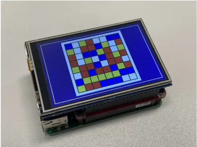
The first (shown in Figure1) consisted of a Raspberry Pi 3 fitted with a full-colourLiquid Crystal Display (LCD)graphics display panel.
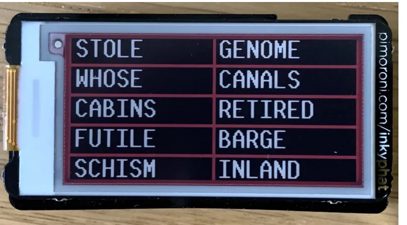
This device was used in conjunction with an implementation of a four-colour pictogram. A second device (shown in Figure2) consisting of a smaller Raspberry Pi Zero W — and a three-colourElectronic Ink (eInk)display ([3]) was also also built; this was used with a word-list observation.
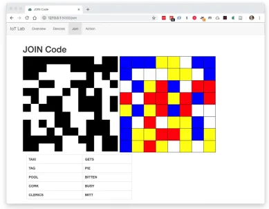
Both of these were demonstrated in combination with a simple web-based C2 server; which was configured to show either a two or four-colour pictogram or the word list. An example of this is shown in Figure3.
4. Technologies for automated Observation-based Identity Confirmation
For scenarios with a large number of devices, or where devices are expected to be deployed autonomously without a human presence, it may be necessary or desirable to adopt machine-based observation.
For this to work, a trustedobserver nodemust be present within theC2network — and must have already securely joined (for example using a human-moderated observation — as described in the previous section). This observer will then utilize one or more techniques to observe the value presented by the joining device, and to confirm that this matches the value that theC2server had transmitted.
Figure 1.An example IoT device — built from a Raspberry Pi 3 fitted with a full-colour LCD graphics display panel
observer node must also be securely sent a copy of the code. Specifically, once theC2server receives an automated join request from a device, the server will respond by sending anOBSERVED_JOIN_RESPONSE
message to the device, as well as anOBSERVATION_REQUESTmessage to the observer. Both of these messages contain a copy of the 128-bit nonce value to be used for the comparison — and each message is encrypted using the recipient’sSRUPpublic-key; ensuring that only that recipient is able to decrypt the data and read the value.
Once the observer and the device each have their own copy of the nonce: the device should present the value to the observer for comparison and onwards signalling.
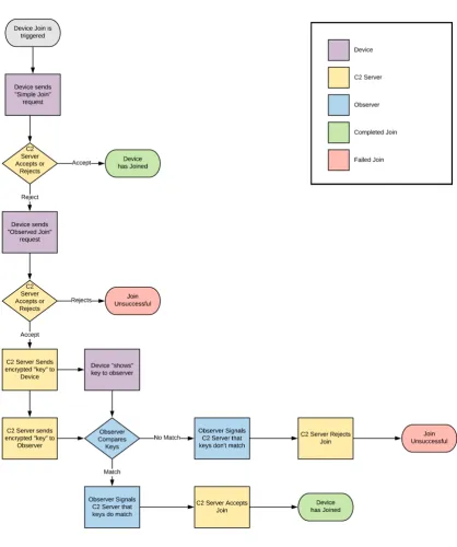
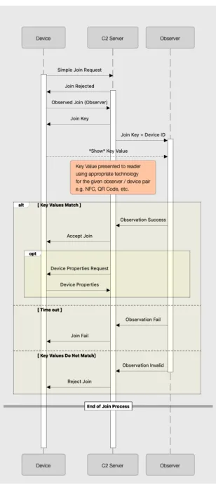
A flowchart illustrating the observed join process is shown in Figure4
In this work, two sets of technologies have been examined to provide this observation.
4.1. Visual Observation Technologies
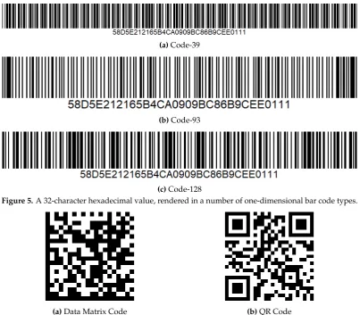
One set of technologies that can be adopted for the observation is machine-readable visual codes — such as barcodes, QR or Data Matrix codes.
Conventional one-dimensional barcodes can store a maximum of around 100 characters (for example Code 128 is defined in [4] and can store 103 data symbols); however two-dimensional barcodes such as the QR Code or Data Matrix (defined [5]) can store over 1000.
ForSRUPobservations — we need to encode a 128-bit value: here aUniversally Unique Identifier (UUID)rendered as a string of 32 hexadecimal characters ([6]). As such any display hardware capable of displaying either a one to two-dimensional barcode could be adopted — along with any barcode technology capable of displaying 32 hexadecimal characters (e.g. Code-128, Code-93 or Code-39).
The disadvantage of linear codes is that for a 32-character code, the resulting barcode is quite long — exceeding the convenient aspect-ratio and dimensions of many displays without unduly squeezing
Figure 2.An example IoT device — built from a Raspberry Zero W fitted with a three-colour eInk display
Figures 5a, 5b, 5c: show the same 32-character hexadecimal value
(58D5E212165B4CA0909BC86B9CEE0111), rendered in a number of one-dimensional codes; and Figures6a, &6bshow the same data rendered as two-dimensional codes.
Experimentation using codes for the sameUUIDvalue — rendered on anLCDdisplay, and read using a smart-phone camera showed that only Code-93 and Code-128 linear barcodes could be reliably read (and that Code-93 was most often read). Code-39 format barcodes were not readable.
Two-dimensional codes on the other hand, are already more suitable to being rendered on a display, due to their square shape — and both Data Matrix and QR codes could be easily read by the app, with approximately the same accuracy.
The Data Matrix code has some potential advantages over the QR code — including the resulting size of the code required for a given length of data being smaller; and improved detection and error correction ([7]).
Further experimentation was conducted using a Raspberry Pi & camera — looking to automatically locate and extract a 32-character hexadecimal value encoded as a two-dimensional barcode. Unlike the previous example, here the code was not manually aligned with the reader: but rather the software was required to identify where in the image streamed from the camera, the barcode was located before it could be decoded.
In both cases the Pi (a Raspberry Pi 3B+) fitted with a Raspberry Pi Camera Module, was running Python code to process the image. For the Data Matrix code, thepylibdmtxlibrary ([?]) was used; and the QR codes were read using thepyzbarlibrary ([?]).
In both cases the code was tweaked to maximize performance. With the Data Matrix code, the best performance was achieved when processing a 320 x 240 grayscale .PNG file (taken from an video capture of the camera being shown the code): and it took an average of 12.7s per image to detect and extract the code (in contrast to less than a second when the DM code is manually cropped from the image file). This is unacceptably slow for a system processing video frames, and is in in contrast to the
pyzbarlibrary, searching for QR codes — which was shown to manage to process several frames per second.
Figure 3.An example web-based C2 interface for an IoT system, showing an example display depicting a range of human-comparable display options.
4.2. Radio Frequency Identification
In addition to a visual observation — a short-range RF link was also adopted to demonstrate a different class of observation node. Although a number of technologies were initially considered (including Bluetooth [8], and the IEEE 802.15.4 Zigbee standard) [9] — the best guarantees as to the physical location of the device in question were achieved when using ultra-short range RF communications such as those used forRadio-Frequency Identification (RFID).
RFIDtechnologies fall into two broad classes: low-frequency devices (operating at 125 kHz in Europe); and high-frequency devices operating at 13.56 MHz. [10].
Low frequency systems typically have an operating range of several inches; but have very low data transfer capabilities: and are only used with simple passivetagscontaining a static serial number determined at the time of manufacture. Such devices are typically used for asset tracking. High frequency systems may store up to 4Kb of data [11], and may be writable as well as readable. This class of tag is often produced in acredit-card sizedform-factor — and are often used to provide security access tokens, as well as cashless ticketing in public transportation systems.
Near-Field Communication (NFC)also operates on the 13.56 MHz frequency — and supports active communication between two devices, over a range of a few centimetres.
Despite (or perhaps because of) its ubiquity within the security (RFID) and banking sector (NFC
for contactless payments) the state of easily accessible and open-source software to support operations more complex than reading or writing to simple tags, is somewhat limited.
Figure 4.A flowchart illustrating the observed join process: showing the roles of each of the three entities involved.
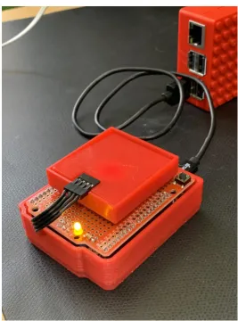
A simple device was constructed to utilizeSNEP, utilizing open-source example C code: and based on at the PN532 NFC ([15]) chipset connected using theInter-Integrated Circuit Protocol (I2C). This was interfaced to a Raspberry Pi as a USB serial device, using an Arduino development board, based on the Atmel ATMega32U ([16]) microcontroller. This is shown in figure7.
5. Implementing Observation-based Identity Confirmation, with a machine-moderated join
(a)Code-39
(b)Code-93
(c)Code-128
Figure 5.A 32-character hexadecimal value, rendered in a number of one-dimensional bar code types.
(a)Data Matrix Code (b)QR Code
Figure 6.The 32-character hexadecimal value, rendered as two-dimensional bar code types.
During this work, the pySRUP library was modified to fully support human and machine based observations. The web-based C2 interface was also modified to support observation.
5.1. Sequence Diagram
The full information exchange process that occurs during the machine moderated observed join process is illustrated as a sequence diagram in Figure8.
5.2. Hardware
Two sets of devices were constructed: around the Raspberry Pi hardware: one using the visual recognition scheme; and one to useNFC.
The visual device was identical to the one used for the human-readable pictograms; with a simple observer constructed from a Raspberry Pi fitted with a camera module.
TheNFChardware consisted on two Raspberry Pi’s connected overUSBto the PN532 modules described previously. One was configured as anNFCobserver; and a second as a joining device.
In the case of both the visual and the NFC devices, the same pySRUP library code was utilized — with the devices only required to specify different operation in the call-back function relating to the observation and presentation of the identity confirmation.
5.3. Operation
Figure 7. An NFC Observer device: consisting of a PN532 NFC module, connected viaI2Cto a
development board based on an Atmel ATMega32U4 microcontroller: connected to a Raspberry Pi via
Universal Serial Bus (USB).
In either case, the outcome of an observation attempt is one of three states: either the code was read correctly (VALID), or an invalid code was read (INVALID), or no code could be read and the observation operation timed-out (FAILED). For this time example system — in the event that the observer signalled back to theC2server that it failed to read a value — theC2server would simply reissue the observation request to both the device and the observer. In a real-world system, the implementation should cap the number of failed read requests by a given device to a (highly system and implementation specific)reasonable number; but for testing purposes this was not capped in the demonstration.
Although a logical observer device is only able to read one type of device communications; multiple logical observers may be combined into a single physical device.
6. Considerations for real-world use of observed join
6.1. Human versus Machine Observation
The question of which type of observer (human or machine) — and the larger question of whether an observed join is required at all — is highly dependant on the specifics of the operation and deployment of a given system.
the communications and as such could use a controlled join. For small-scale deployments, a human-moderated join is an ideal mechanism to control the join, especially since this has no requirement for specialist observation nodes. However, a smartphone application could be utilized as an observer (itself joining via a human-moderated join) — and then subsequently using either the smartphone’s camera for visual recognition, or potentially utilising the phone’sNFCcapabilities to read values from devices without a user-interface capable of displaying a visual code. Although this implementation has not been explored in this work, the majority of modern smartphones support
NFCfor mobile payment, andApplication Program Interfaces (APIs)exist within major smartphone operating systems to access some or all of the functionality of theNFChardware within the phone.
Human moderated joins provide the highest guarantee of device identity, since the human observer is explicitly able to ascertain that the device in question is the device that’s being joined (especially where the human installer has manually triggered the join operation themselves). It is however least scalable to very large deployments; or for scenarios where there are a large number of join and leave operations expected to be conducted.
For such larger scale operations installed devices could join theC2network, and have their identity validated by a dedicated observation node. For example, within a factory setting an installer could utilize a hand-held observer device usingNFCto positively validate all devices as they installed and joined into the system; or for a distributed sensor application — devices could be joined (and validated) as they are deployed.
6.2. Benefits of Machine Observation
In a real-world deployment, different types of scenario have different requirements for a machine-moderated join. For devices where the deployment conditions prevent the observer node from physically coming into close proximity to the device (such as an observer covering an area deployment) — it may be preferable to conduct an observation via a visual method — and from a longer distance that may be possible with other technologies: although this does require the device to be large enough that both the display, and the device to which it is mounted, are sufficiently visible to the remote observer.
Physical proximity can provide the best guarantee of the identity of the physical device, for scenarios where this is achievable. For example: devices being deployed via a conveyor belt fed system, devices which are at a known and physically small location (such as passing through a door, or gateway), or devices where a human can physically access andtapthe device could all utilize this type of approach.
Although designed around theIoT, and the idea of largely static devices — this approach (and theSRUPprotocol in general) will work well to support broader classes ofsmartdevices — including smart vehicles; although for the purposes of identity validation, neither of the technologies employed in this example implementation work especially well for scenarios where the device is in motion.
For example, in a scenario where the device would only be in the observers field-of-view for a short period careful and accurate timing would be required to ensure that the messages supporting the request have been sent (and arrived) with sufficient time for the observer to be ready to view the device. This may require, for example, that the device makes the request some period of time before it expects to be observable (although the longer the time period between the message and the observation — the greater the risk of another device being detected instead).
place during a time period when the device was static (such as at a control point or barrier — prior to entering the smart system’s control).
6.3. Issues
In the present implementation of the system, a device is required to know the identity of the observer that it wishes to use: in the examples shown above, this is hard-coded into the device’s source code. There is currently noexplicitmechanism withinSRUPto specifically enable transmission of an observer’s identity to a device. This is deliberate — since until or unless a device joins aC2network, it is not defined as to which servers may sendSRUPmessages to it. This is in contrast to the identity of thedefaultC2server for a given device, which is explicitly sent to the device as a part of its initial registration and key exchange process.
Since the device has theSRUPpublic key belonging to the default server (required so that it can be used as a part of the joining process to validate messages from the server) — the server could use the extantDATAmessage within theSRUPprotocol in order to send the identity of the observer that should be used — after the server has refused the initial simple join. This could be trivially implemented by a system using the pySRUP library — by simply adding a data message handler callback function to the device code; and using the existingsend_SRUP_Datamethod from the library, to send the observer ID from the server.
7. Conclusion
This paper has identified how both human and machine-based observation techniques can be used to positively confirm the identity of a device joining aC2network. We have shown that by using these techniques we can utilize a dynamic identity scheme forIoTdevice’s; enabling both guaranteed revocation of prior access to a device by replacing the device identity with a new one, and simplifying the process of device key distribution. We have shown that a a suitable device (running software using the pySRUP library) can securely join aC2network — positivity establishing its identity to the network, with no prior knowledge of the device required by the network; and with only a single
Universal Resource Locator (URL)address for the key-management service required to be supplied to the device.
The software described here can be obtained at:
doi:10.5281/zenodo.3898242
Acknowledgements
This work has been funded by the United Kingdom Defence Science and Technology Laboratory (Dstl). Dstl is a part of the U.K. Ministry of Defence.
1. Poulter, A.J.; Johnston, S.J.; Cox, S.J. SRUP: The Secure Remote Update Protocol. 2016 IEEE 3rd World Forum on Internet of Things (WF-IoT). IEEE, 2016, pp. 42–47. doi:10.1109/WF-IoT.2016.7845397.
2. Poulter, A.J.; Johnston, S.J.; Cox, S.J. Extensions and Enhancements to “the Secure Remote Update Protocol”. Future Internet2017,9, 59. doi:10.3390/fi9040059.
3. Chen, Y.; Au, J.; Kazlas, P.; Ritenour, A.; Gates, H.; McCreary, M. Flexible active-matrix electronic ink display. Nature2003,423, 136–136. Citation Key: chenFlexibleActivematrixElectronic2003, doi:10.1038/423136a. 4. Information technology — Automatic identification and data capture techniques — Code 128 bar
code symbology specification. Technical Report ISO/IEC 15417:2007, International Organization for Standardization, 2007.
7. Kulshreshtha, R.; Kamboj, A.; Singh, S. Decoding robustness performance comparison for QR and data matrix code. Association for Computing Machinery, 2012, CCSEIT ’12, p. 722–731. doi:10.1145/2393216.2393337.
8. Bluetooth Special Interest Group. Specification of the Bluetooth System; 2014.
9. 802.15 WG - Wireless Personal Area Network Working Group. IEEE Approved Draft Standard for Low-Rate Wireless Networks; Number IEEE 802.15.4-2020, 2020.
10. Weis, S.A. RFID (radio frequency identification): Principles and applications.System2007,2, 1–23. 11. Garcia, F.D.; de Koning Gans, G.; Muijrers, R.; Van Rossum, P.; Verdult, R.; Schreur, R.W.; Jacobs, B.
Dismantling MIFARE classic. European symposium on research in computer security, 2008, p. 97–114. 12. NFC Forum. NFC Data Exchange Format (NDEF) Technical Specification2006.
13. NFC Forum Technical Specification. SNEP: Simple NDEF Exchange Protcol.
14. Lotito, A.; Mazzocchi, D. OPEN-SNEP project: Enabling P2P over NFC using NPP and SNEP. 2013, p. 1–6. doi:10.1109/NFC.2013.6482447.
15. NXP Semiconductors B.V.. PN532/C1 - Near Field Communication (NFC) controller2017.
16. Microchip Technology Inc.. ATmega16U4 / ATmega32U4 — 8-bit Microcontroller with 16/32K bytes of ISP Flash and USB Controller2016.
17. Poulter, A.J.; Johnston, S.J.; Cox, S.J. pySRUP – Simplifying Secure Communications for Command Control in the Internet of Things. 2019 IEEE 5th World Forum on Internet of Things (WF-IoT), 2019, pp. 273–277. doi:10.1109/WF-IoT.2019.8767205.