IJEDR1502026
International Journal of Engineering Development and Research (www.ijedr.org)138
Modelling and Control Strategy of Induction Motor
Using Fuzzy Logic Control Technique
1Kishan jobanputra,2Savan dobariya,3Nakul athle, 4Vipesh suthar, 5Dr. D.M Patel
Electrical engineering department,
Babaria institute of technology (BITS edu campus), Varnama, Vadodara, India
________________________________________________________________________________________________________
Abstract - An induction motor is an asynchronous AC (alternating current) motor. The least expensive and most widely used induction motor is the squirrel cage motor. The interest in sensor less drives of induction motor (IM) has grown significantly over the past few years due to some of their advantages, such as mechanical robustness, simple construction, and less maintenance. These applications include pumps and fans, paper and textile mills, subway and locomotive propulsions, electric and hybrid vehicles, machine tools and robotics, home appliances, heat pumps and air conditioners, rolling mills, wind generation systems, etc. So, Induction motors have been used more in the industrial variable speed drive system with the development of the vector control technology. This method requires a speed sensor such as shaft encoder for speed control. This paper presents a novel design of a Takagi-Sugeno fuzzy logic control scheme for controlling some of the parameters, such as speed, torque, flux, voltage, etc. of the induction motor. Induction motors are characterized by highly non-linear, complex and time-varying dynamics and inaccessibility of some of the states and outputs for measurements, and hence it can be considered as a challenging engineering problem. The development of advanced control techniques has partially solved induction motor’s speed control problems; because they are sensitive to drive parameter variations. Fuzzy logic based controllers are considered as potential candidates for such an application. Further, the Takagi-Sugeno control strategy coupled with rule based approach in a fuzzy system when employed to the induction motor yields excellent results compared to the other methods as this becomes a hybrid & integrated method of approach. Such a mixed implementation leads to a more effective control design with improved system performance, cost-effectiveness, efficiency, dynamism, & reliability. The closed loop speed control of the induction motor using the above technique thus provides a reasonable degree of accuracy which can be observed from the results depicted at the end. The simulation results presented in this paper show the effectiveness of the method developed & have got a wide number of advantages in the industrial sector & can be converted into a real time application using some interfacing cards.
Keywords - TS Model, Fuzzy Logic, Controller, Simulink, Matlab, Induction motor, closed loop, Parameter, Robustness
________________________________________________________________________________________________________
I.INTRODUCTION
IJEDR1502026
International Journal of Engineering Development and Research (www.ijedr.org)139
identification methods which are only effective under certain narrow working states and provide global dynamic description based on which further control of such systems may be carried out. Since, the induction motor is a complex nonlinear system; the time-varying parameters entail an additional difficulty during the controller design Vector control methods have been proposed by various researchers to simplify the speed control of induction motors so they can be controlled like a separately excited dc machine. Indirect vector control methods decouple the motor current components by estimating the slip speed, which requires a proper knowledge of the rotor time constant. Classical control systems like PI, PID control have been used, together with vector control methods, for the speed control of induction machines. The main drawbacks of the linear control approaches were the sensitivity in performance to the system parameters variations and inadequate rejection of external perturbations and load changes. As an attempt to solve all these deficiencies, problems & difficulties encountered in designing the controller as mentioned in the above paragraphs, we have tried to devise a control strategy using the Takagi-Sugeno fuzzy scheme for the speed control of IM in our paper which has yielded excellent results & this has been applied to the control of electrical drive systems (induction motor). The results of our work have showed a very low transient response and a non-oscillating steady state response with excellent stabilization. The structure of the work (flow / organization of the paper) presented in this research paper is organized in the following sequence. A brief review of the literature survey of the related work was presented in the previous paragraphs in the introductory section. Section 3 presents the mathematical modeling of the induction motor. Review about the Takagi-Sugeno control scheme used in the design of the controller in our case is presented in section 4. The TS based fuzzy controller design is presented in section 5. The section 6 shows the development of the simulink model for the speed control of the induction motor. The graphical results of the simulation & the discussion are presented in it. This is followed by the conclusions in the concluding Section & references.FIG 1: Fuzzy control system
II.APPLYING OF FUZZY LOGIC TO ELECTRICAL DRIVES:
Fuzzy control is based on the fuzzy logic theory which was first proposed by Zadeh. Fuzzy controllers are rule-based controllers that use “if–then” format for the control process. In this format, several variables could be used either in condition or conclusion side of the “if–then” rules. As a result, the mathematical model of the system is not required in fuzzy control, so it can be applied to nonlinear systems. The structure of fuzzy controller is shown in Figure 2.
FIG 2: Fuzzy control structure
As seen in Figure 2, the fuzzy inference system consists of three main parts which can be illustrated as follows:
1. Fuzzification
Fuzzification is the process in which a crisp values are transformed into grades of membership for linguistic terms of fuzzy sets. The most commonly used method is the singleton fuzzifier.
2. The fuzzy inference engine
Fuzzy inference engine is the process that relates input fuzzy sets to output fuzzy sets using if-then rules and fuzzy mechanism to derive a reasonable output form crisp or fuzzy inputs. There are two types of fuzzy inference systems: Mamdani-type and Sugeno-type. Mamdani fuzzy inference system is the most commonly used method; since it has the advantages of intuition, wide acceptance and suitability to human input.
3. Defuzzification
IJEDR1502026
International Journal of Engineering Development and Research (www.ijedr.org)140
(centroid) defuzzification. This technique was developed by Sugeno in 1985, and it had very accurate results compared with other methods.III.MODELING OF INDUCTION MOTOR:
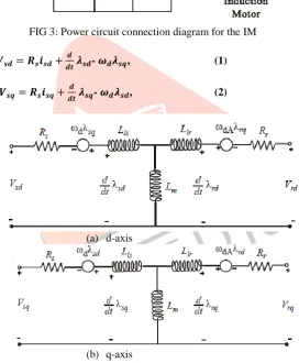
In the control of any power electronics drive system (say a motor), to start with a mathematical model of the plant is required. This mathematical model is required further to design any type of controller to control the process of the plant. The induction motor model is established using a rotating (d, q) field reference (without saturation) concept. The power circuit of the 3-φ induction motor is shown in the Fig. 3. The equivalent circuit used for obtaining the mathematical model of the induction motor is shown in the Fig. 4. An induction motor model is then used to predict the voltage required to drive the flux and torque to the demanded values within a fixed time period. This calculated voltage is then synthesized using the space vector modulation.
FIG 3: Power circuit connection diagram for the IM
- , (1)
- , (2)
(a) d-axis
(b) q-axis
FIG 4 : Equivalent circuit of induction motor in d-q frame
- , (3)
- (4)
IJEDR1502026
International Journal of Engineering Development and Research (www.ijedr.org)141
[ ] = M [ ]; M = [
] (5)
The electrical part of an induction motor can thus be described by a fourth-order state space model (4×4), which is given in Eq.(6), by combining equations (1) - (5) as
ʹ [ ] = × ( [ ] [ ] [ ]) (6)
Where, A is given by ( ) ( ) ( ) ( ) ( ) ( ) (7)
By superposition, i.e., adding the torques acting on the d-axis and the q-axis of the rotor windings, the instantaneous torque produced in the electromechanical interaction is given by
( ) (8)
The electromagnetic torque expressed in terms of inductances is given by
( ) (9)
The mechanical part of the motor is modeled by the equation [17] as = = ( ) (10) where,
= Equivalent MI,
= = − ,
= , = , = + , = +
This IMs mathematical model is further used to design a controller using TS-fuzzy control strategy.
IV.TAKING-SUGENO CONTROL SCHEME
In this section, a brief review of the Takagi and Sugeno control strategy to control various system parameters of the plants is presented. Takagi and Sugeno proposed a new type of fuzzy model (TS model) which has been widely used in many disciplines, especially in the control of dynamical systems, such as induction motors, DC motors, AC motors, etc. This fuzzy model is described by IF-THEN fuzzy rules which represent local linear input-output relations of a non-linear system. The main feature of a Takagi-Sugeno fuzzy model is to express the local dynamics of each fuzzy implication (rule) by a linear system model. The overall fuzzy model of the system is achieved by fuzzy “blending” of the linear system models. These TS models use fuzzy rules with fuzzy antecedents and functional consequent parts, thereby qualifying them as mixed fuzzy or nonfuzzy models. Such models can represent a general class of static or dynamic non-linear mappings via a combination of several linear models. In this context, the TS control model which is being used by us to design the controller for the speed control of induction motor is explained as follows.
IJEDR1502026
International Journal of Engineering Development and Research (www.ijedr.org)142
Where (x), j =1…m are polynomial functions of the inputs and represent local models used to approximate the response of the system in the region of the input space represented by the antecedentFuzzy models relying on such rules are referred to as singleton fuzzy models. This class of fuzzy models can employ all the other types of fuzzy reasoning mechanisms, because they represent a special case of each of the above escribed fuzzy models. Parameter varying systems which possess m working state characteristic variables, q inputs and single output can be described by the TS fuzzy model consisting of R rules, where the rule can be represented as,
Rule i: if , , ˄ ,and , Then, = + + ˄ + ,
i=1, 2, ˄…R. = 1, 2, ˄… (12)
where, R is the number of rules in the TS fuzzy model, ( j = 1,2,3,..., Λ,...m) is the characteristic variable, which reflects the working state of the systems and can be selected as input, output or other variables affecting the parameters of the system dynamics.
Here, (l = 1, 2, 3... Λ...q) is the model input and is the output of the rule. For the rule, , is the fuzzy sub-set of . is the coefficient of the consequent terms. Is the fuzzy partition number of . For simplicity of induction, we let = r and r is determined by both the complexity and the accuracy of the model. Once a set of working state variables ( , ,…, Λ, ) and the model input variables ( , ,…, Λ, ) are available, then the output of the TS model under such working states can be calculated by the weighted average of each as,
y = ∑ ∑
(13)
Where is determined by consequent equation of the rule. The truth-value of the rule can be calculated as [15]
= ⋀ ( ). (14)
Furthermore, Eq. (13) can be rewritten as [15]
y = (∑ ∑ )
∑ , (15)
Which is nothing but the final output of the system and is the weighted average of all the rule outputs (from i to R)?
From Eq. (15), one can see that the TS fuzzy model can be expressed as an ordinary linear equation under certain working states, since the truth-value is only determined by the working state variables. As varies with the working state, TS fuzzy model becomes a coefficient-varying linear equation. For all possible varying ranges of the various parameters, the TS fuzzy model reflects the relationships between these model parameters and the working states. Thus, the global dynamic characteristics of the parameter varying systems can be represented.
V. TAKING-SUGENO CONTROL SCHEME:
A controller is a device which controls each & every operation in the system making decisions.
From the control system point of view, it is bringing stability to the system when there is a disturbance, thus safeguarding the equipment from further damages. It may be hardware based controller or a software based controller or a combination of both. In this section, the development of the control strategy for control of various parameters of the induction machine such as the speed, flux, torque, voltage, stator current is presented using the concepts of Takagi-Sugeno based fuzzy control scheme, the block diagram of which is shown in Fig.5.
To start with, we design the FLC, then combine with the TS scheme, finally to obtain the hybrid controller. Fuzzy logic is one of the successful applications of fuzzy set in which the variables are linguistic rather than the numeric variables & emerged as a consequence of the 1965 proposal of fuzzy set theory by Lotfi Zadeh. Linguistic variables, defined as variables whose values are sentences in a natural language (such as large or small), may be represented by the fuzzy sets. Fuzzy set is an extension of a „crisp‟ set where an element can only belong to a set (full membership) or not belong at all (no membership). Fuzzy sets allow partial membership, which means that an element may partially belong to more than one set.
IJEDR1502026
International Journal of Engineering Development and Research (www.ijedr.org)143
These rules are expressed in the form of conditional statements. Our basic structure of the fuzzy logic coordination controller to damp out the oscillations in the power system consists of 3 important parts, viz., fuzzification, knowledge base – decision making logic (inference system) and the defuzzification, which are explained in brief in further paragraphs.Fig. 5: Block diagram of the TS-fuzzy logic control scheme of the IM
The inputs to the FLC, i.e., the error & the change in error is modeled using the Eq. (16) as
e (k) = - (16) Δe (k) = e (k) - e (k - 1)
Where is the reference speed, is the actualrotor speed, is the e(k) error and Δ e(k) is thechange in error.
The internal structure of the fuzzy coordination unit with the TS control scheme is shown in the Fig. 3. The necessary inputs to the decision-making unit blocks are the rule-based units and the data based block units. The fuzzification unit converts the crisp data into linguistic variables. The decision making unit decides in the linguistic variables with the help of logical linguistic rules supplied by the rule base unit and the relevant data supplied by the data base. The output of the decision-making unit is given as input to the de-fuzzification unit and the linguistic variables are converted back into the numeric form of data in the crisp form.
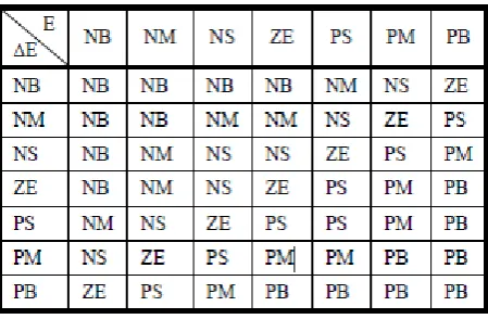
The decision-making unit uses the conditional rules of „IF-THEN-ELSE‟, which can be observed from the algorithm mentioned in the also for developing the fuzzy rules below. In the fuzzification process, i.e., in the first stage, the crisp variables, the speed error & the change in error are converted into fuzzy variables or the linguistics variables. The fuzzification maps the 2 input variables to linguistic labels of the fuzzy sets. The fuzzy coordinated controller uses the linguistic labels. Each fuzzy label has an associated membership function. The inputs are fuzzified using the fuzzy sets & are given as input to fuzzy controller. The rule base for the decision-making unit is written as shown in the table I. The developed Takagi-Sugeno fuzzy rules (7 × 7 = 49) included in the fuzzy coordinated controller.
Table I: Rule base for controlling the speed
IJEDR1502026
International Journal of Engineering Development and Research (www.ijedr.org)144
must be converted into numerical output, i.e., they have to be defuzzified. This process is what is called as defuzzification. Defuzzification. Defuzzification is the process of producing a quantifiable result in fuzzy logic.The defuzzifcation transforms fuzzy set information into numeric data information. This defuzzification process along with the operation of fuzzification is critical to the design of fuzzy systems as both of these operations provide nexus between the fuzzy set domain and the real valued scalar domain. There are so many methods to perform the deffuzification, viz., centre of gravity method, centre of singleton method, maximum methods, the marginal properties of the centroid methods & so on. In our work, we use the centre of gravity method. The output of the defuzzification unit will generate the control commands which in turn is given as input (called as the crisp input) to the plant through the inverter. If there is any deviation in the controlled output (crisp output), this is fed back & compared with the set value & the error signal is generated which is given as input to the TS-fuzzy controller, which in turn brings back the output to the normal value, thus maintaining stability in the system. Finally, the controlled o utput signal, i.e., y is given by Eq. (17) as
y = ∑ ∑ ∑
⁄ , (17)
This controlled output y is nothing but the final output of the controller and is the weighted average of all the rule based outputs. From Eq. (17), one can see that the TS fuzzy model can be expressed as an ordinary linear equation under certain working states since the truth-value is only determined by the working state variables. The main advantage of designing the TS based fuzzy coordination scheme to control the speed of the IM is to increase the dynamic performance & provide good stabilization.
VI. DEVELOPMENT OF SIMULINK MODEL
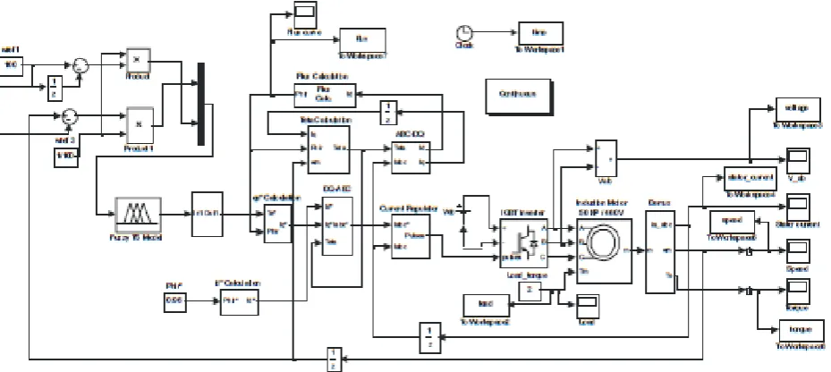
The block model of the induction motor system with the controller was developed using the power system, power electronics, control system, signal processing toolboxes & from the basic functions available in the Simulink library in Matlab / Simulink. In this paper, plots of voltage, torque, speed, load & flux, etc are plotted as functions of time with the controller and the waveforms are observed on the corresponding scopes after running the simulations. The entire system modeled in Simulink is a closed loop feedback control system consisting of the plants, controllers, samplers, comparators, feedback systems, the mux, de-mux, summers, adders, gain blocks, multipliers, clocks, sub-systems, integrators, state-space models, subsystems, the output sinks (scopes), the input sources, etc. The developed simulink model for the control of various parameters of the SCIM is shown in the Fig. 6.
VII.SIMULINK RESULTS & DISCUSSIONS
Simulink model with the controller for the speed control of IM is developed in Matlab 7 as shown in the Fig. 6. The simulation is run for a specific amount of time (say 2 to 3 secs) in Matlab 7 with a reference speed of 100 rads / sec
{ ( )⁄ } 955 rpm & with a load torque of 2 N-m.
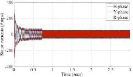
Note that the fuzzy coordinated TS controller consists of 3 basic blocks viz., fuzzification, inference, and the de-fuzzification blocks as shown in the Fig. 6. A set of 49 fuzzy rules are written and called in the form of a file in the developed Simulink model with the controller. While the simulation is run, the 2 fuzzy inputs are then given to the controller (Takagi-Sugeno-fuzzy), where the output is obtained thereafter. The response curves of flux, load, torque, terminal voltage, and speed & stator currents v/s time are observed on the respective scopes & are shown in the Figs. 7 – 11 respectively after importing the scope data into the workspace and plotting them.
IJEDR1502026
International Journal of Engineering Development and Research (www.ijedr.org)145
Fig. 6 : The developed simulink model with the TS based Fuzzy logic controllerFig. 7 : Plot of flux vs. time Fig. 8 : Plot of load vs. time
IJEDR1502026
International Journal of Engineering Development and Research (www.ijedr.org)146
Fig. 11: Plot of 3-φ stator currents vs. timeVIII.CONCLUSIONS
A systematic approach of achieving robust speed control of an induction motor drive by means of Takagi-Sugeno based fuzzy control strategy has been investigated in this paper. Simulink models were developed in Matlab 7 with the TS-based fuzzy controllers (hybrid controller) for the speed control of IM. The control strategy was also developed by writing a set of 49 fuzzy rules according to the TS control strategy. The main advantage of designing the TS based fuzzy coordination scheme to control the speed of the IM is to increase the dynamic performance & provide good stabilization. Simulations were run in Matlab 7 & the results were observed on the corresponding scopes. Graphs of speed, torque, stator current, flux, etc. vs. time were observed. The outputs take less time to stabilize, which can be observed from the simulation results. But, from the incorporation of the TS based fuzzy coordination system in loop with the plant gave better results there by stabilizing the plant very quickly. The developed control strategy is not only simple, reliable, and may be easy to implement in real time applications, but also cost-effective as when this control scheme is implemented in real time, the size of the controller will become very small. Collectively, these results show that the TSfuzzy controller provides faster settling times, has very good dynamic response & good stabilization.
IX.REFRENCES
1) Skvarenina T.L., The Power Electronics Handbook. CRC Press, 2002.
2) Mendel J.M., “Fuzzy Logic Systems for Engineering: A tutorial,” Proceedings of the IEEE, Vol. 83, pp. 345-377, 1995. 3) S. N. Sivanandam, S. Sumathi and S. N. Deepa, “Introduction to fuzzy logic using Matlab”, Springer-Verlarg Publications,
2007.
4) M. Sugeno and G. T. Kang, “Structure identification of fuzzy model”, Proc. on the Fuzzy Sets and Systems, Vol. 28, pp. 15-33, 1988.
5) Bose B. K., Modern Power Electronics and AC Drives, Pearson Education, Inc., India, 2002.
6) Ashok Kusagur, S. F. Kodad, B V. Sankar Ram, “AI based design of a fuzzy logic scheme for speed control of induction motors using SVPWM technique”, Proc. Int. Jr. Comp. Sci. & Network Security, Vol. 9, No. 1, pp. 74 - 80, Jan. 2009. 7) T. Takagi and M. Sugeno, “Fuzzy identification of system and its applications to modeling and control”, Proc. IEEE Trans.
on System Man and Cybernetics, Vol. SMC- 15, No. 1, pp. 116-132, 1985.
8) M. Sugeno and K. Tanaka, “Successive identification of a fuzzy model and its applications to prediction of a complex system”, Proc. Fuzzy Sets and Systems, Vol. 42, pp. 315-334, 1992.
9) Mouloud Azzedine Denai, Sid Ahmed Attia, “Fuzzy and Neural Control of an Induction Motor”, Proc. Int. J. Appl. Math. Comput. Sci., Vol. 12, No. 2, pp. 221–233, 2002.
10) Vas P., “Vector Control of AC Machines”, Oxford University Press, London, UK, 1990.
11) Trzynadlowski A.M., “The Field Orientation Principle in Control of Induction Motors”,Kluwer Pub., Dordrecht, 1994. 12) Cao S.G., Rees N.W. and Feng G., “Analysis and design of fuzzy control systems using dynamic fuzzy state space Models”,
Proc. Of the Trans. on IEEE Trans. Fuzzy Syst., Vol. 7, No. 2, pp. 192–199, 1999.
13) Chen C-Li and Chang M-Hui, “Optimal design of fuzzy sliding mode control: A comparative study”, Fuzzy Sets Syst., Vol. 93, pp. 37–48, 1998.
14) Shaw A. and Doyle F., “Multivariable nonlinear control application for a high purity distillation column using a recurrent dynamic neuron model”, J. Process Contr., Vol. 7, No. 4, pp. 255–268, 1997.
15) Jinjie Huang, Shiyong Li, Chuntao Man, “A TS type of fuzzy controller based on process of input output data”, Proc. of 42nd IEEE Conf. on Decision & Control (CDC‟03), Hawai, USA, pp. 4729-4734. Dec. 2003.
16) Kazuo Tanaka, Hua O. Wang, “Fuzzy Control Systems Design and Analysis: A Linear Matrix Inequality Approach” John Wiley & Sons, Inc., USA. 2002.
17) Giovanna Castellano, “A neuro-fuzzy methodology for predictive modelling”, Ph.D. Thesis, Dept. of Comp. Sci., Univ. of Bari, 2000.
18) Xie Keming, TY Lin, Zhang Jianwei, “The Takagi-Sugeno fuzzy model identification method of parameter varying systems”, Proc. Rough Sets Current Trends Conf., RSCTC’98, Warsaw, Poland, Jun. 22-26, 1998.
IJEDR1502026
International Journal of Engineering Development and Research (www.ijedr.org)147
20) Satean Tunyasrirut, Tianchai Suksri, and Sompong Srilad, “Induction Motor using Space Vector Pulse Width Modulation”,Proc. of the World Academy of Science, Engineering Fuzzy Logic Control for a Speed Control of And Technology, Vol. 21, pp. 71 - 77, Jan. 2007.
21) R. Arulmozhiyal, K. Baskaran, “Space Vector Pulse Width Modulation Based Speed Control of Induction Motor using Fuzzy PI Controller”, Proc. of the International Journal of Computer and Electrical Engg., Vol. 1, No. 1, pp. 98-103,April 2009.
22) Zadeh L.A., “Fuzzy sets,” Information and Control, Vol. 8, p.p. 338-353, 1965.
23) Arkhipov M., Krueger E., Kurtener D., “Evaluation of Ecological Conditions Using Bioindicators: Application of Fuzzy Modeling” International Conference on Computational Science and its applications - ICCSA 2008, Part I, LNCS 5072, pp. 491-500, 2008.