Implementation of DCS Technology through SCADA in
the Production Line of Universal Motor
Lipika Rachel John
1, Bagyaveereswaran V
2, Karmegham S
3Control and AutomationSELECT1,2 Maintenance Department3,VIT University1,2 IFB Industries3 [email protected]1,[email protected]2
Abstract-The aim of this multidisciplinary paper to implement distributed control system (DCS) to monitor the
online operations going on in the quality inspection and maintenance line of universal motor manufacturing industry. DCS is an archetype of automated control system that is distributed throughout the plant to provide commands to different parts of various machines. It acts as an entire framework in accordance with usual engineering practices for programming, simulating and testing the distributed network. The complete execution of DCS technology is achieved through PLC programming and design of SCADA. Therefore this paper mainly focuses on the design of SCADA for all the PLC operated machines and users with secure ingress to SCADA screen can get personalized view of important plant information. And thereby enables the user to monitor and control the online processes even from a remote place. The network installation and communication setup is maintained through Ethernet protocol. This column also pursues an overview of data logging and SMS logging. Data logging is acquired through creation of trends and SMS logging is achieved through GSM modem. Thus the user can acquire the real time production data through data logging and SMS logging helps the authorized head to receive an SMS notification regarding the production status on their mobile.
Index Terms-PLC: Programmable logic controller; DCS: Distributed control system; SCADA: Supervisory
control and data acquisition; HMI: Human machine interface;RTU: Remote terminal unit; CAT6: Category 6 cable; GSM: Global system for mobile communication.
1. INTRODUCTION
Industrial automation is the leading technology used in most of the manufacturing industries. It comprises the use of computers and recent information technologies for operating the different machineries in a plant thus reducing the manpower and improving the efficiency of production. Online monitoring of all the plant operations and its control is a major challenge at these plants. The increasing rejection rate of products at these plants is a clear indication of absence of proper maintenance and inspection. A wide range of sources and collection of large amount of data from these sources are needed to inspect the process, but it becomes time consuming. Most of the industries are using the traditional approach of HMI to monitor the operations however HMI can provide just the basic details of each machine individually. It does not provide a solution for wide-area monitoring. Though smart control techniques are used for large systems they are not cost effective.
In this project, as a contradictory to the usual methodology, cost effective DCS technology is being used. DCS allows plant operations and maintenance activities to be directly linked to graphical objects in SCADA. SCADA systems are used to monitor and control the manufacture of motors. To automate the
data collection and compute key performance, indicators in real time SCADA solutions could be a cost effective solution. The key factor of a SCADA system is that it provides the complete information regarding the availability, performance and quality of a single machine as well as the entire factory.
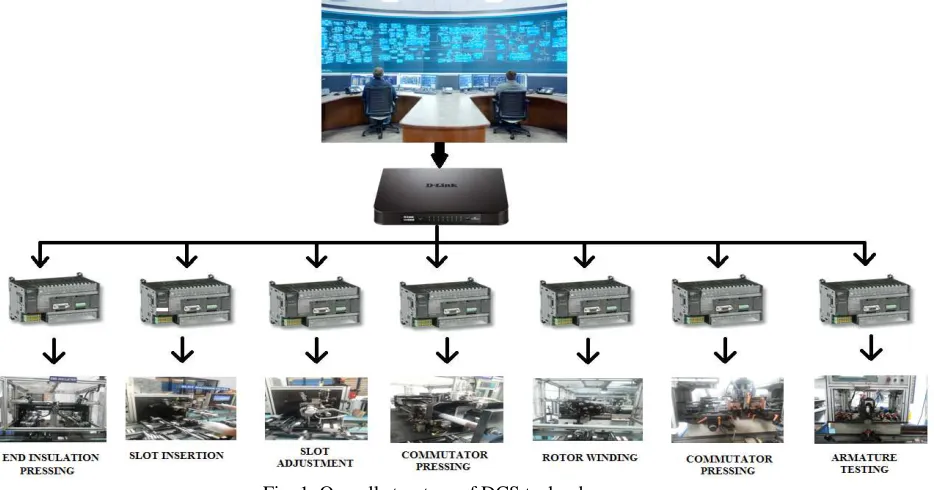
The main goal of this project is to design a PLC based DCS system for the manufacturing process of a universal motor which is used in washing machine.Universal motors works both in AC and DC supplies. These motors find application in many fields like power tools, food mixers, portable drills etc. The production of universal motor consists of rotor, stator and motor assembly lines. Each of these lines consists of many operations which are automated through PLC program. A typical DCS system consists of a control station, work station and field station as shown in Fig.1.The main PC acts as the control station which consists of the SCADA designs of all the individual machines. The work station is a common dc link. The field station consists of all the required motor manufacturing operations like end insulation pressing, slot insertion etc... Each plc unit is associated with motor manufacturing processes which are distributed within the plant are connected to a common dc link using twisted cables. This dc link is connected to the main control station through CAT6 cable.
Fig. 1. Overall structure of DCS technology
The working set up of each machine is also shown in individual HMI screens. The main objectives of a distributed control system are:-
• Controlling- Controlling the operation of all PLCs using a single master.
• Online monitoring- Monitoring the ongoing processes on a SCADA screen.
• Troubleshooting- Identifying the error.
• Switching- In case of any system failure, the particular system can be replaced thus not affecting the operations of other PLCs.
• Networking capability- The DCS provides networking capability which is useful for business management.
2. LITERATURE REVIEW
In the current era of industrialization, the domain of automation has a major role to play. On contemplation of automation, a person must be able to view all the processes going on in the industry and status of various machines remotely. Apart from this, a system should be designed to provide certain control facilities to the machines, parameters and processes from a distant location. All the above stated objectives can be achieved by designing a SCADA system.1In an industry a large number of processes may be taking place simultaneously to deliver a final product. The system which combines all these machine operations along with its control actions contribute to a DCS system.
DCS technology is widely used over many fields which includes site specific irrigation, telecom industry, waste water treatment plants, power
generation systems etc..2 For any system monitoring, data logging is necessary. Traditional collection of data like barcode technology is not efficient and has high chance of causing errors.As an improvement, RFID technology emerged which provides an opportunity to gather accurate and real time data acquisition.3 RFID technology is a system that transmits the identity of an object using a unique serial number in the form of radio waves.4 In the proposed system all the rotors passing through the pallet is scanned using RFID tags.
Most of the process and manufacturing industries work with HMI screens to view the current status of the plant. Each machine will have its own HMI screen with text and data values being updated automatically. An HMI screen is designed by a professional keeping in mind that an operator handling the machine can understand and work with it easily.5 In the proposed system, apart from HMI screens which display the status of individual machines, SCADA screens are also used to monitor the entire plant operations. The SCADA system has many advantages over HMI. The HMI provides single machine control where as in SCADA large number of machines can be controlled simultaneously.6HMI provides slower speed compared to SCADA.In HMI, the communication speed is about 256kbps while in SCADA it is about 1000Mbps.7 HMI displays only the main processes where as SCADA displays the entire graphical layout of the system.HMI is a part of the complete control system, SCADA.
The traditional approach of system design in industrial applications was done through MATLAB software.The focus was on design of communication
9
protocol for remote data accessmanagement.8SCADA is an advanced system that allows an operator to monitor and control the processes by sending messages or commands to the external world.9It makes the system flexible, reliable and effective cost management. It also provides plc interlocking and real time data sharing. The different blocks that makes a SCADA system are HMI, communication interface, PLC, SCADA programming, RTU and supervisory system.10The communication system plays a key role to meet the objective of SCADA. Most commonly IEEE802.22 standards are used. There has been an improved trends towards distributed processing, standard systems, standard software, smarter RTUs and improved man-machine interface.11 Oil and gas industries have SCADA solutions for automation and monitoring. SCADA design in oil recovery plants, is based on hybrid single board computer where the sensor inputs are processed prior to be uploaded to a central database.12
3. PROPOSED METHODOLOGY
3.1. Block diagram
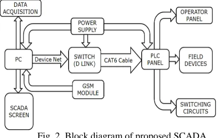
The central workstation, field control unit, field devices and communication medium together constitute an entire DCS framework. The block diagram is shown in Fig.2.Themaster computer or PC in which the SCADA designs are made acts as the central control workstation. From the PC data is logged at regular interim through trend charts. A GSM module is also connected to the PC which helps in message logging. The switch (D link) acts as the vital hub which links the PC to field units. The switch is connected to the PC through Device net. A CAT6 cable establishes connection between switch and PLC panel. The different machine operations in the line along with their plc panels constitute the field control unit. The HMI serve as the operator control panel. The PC, D-link and PLCs are powered from a power supply. A Power supply of S 100-24 is given to the hub. The input voltage and current ratings are 100-120VAC and 1.9A respectively.
[image:3.595.312.536.100.242.2]There are different numbers of steps in the manufacturing processes of motor. The machine operations which are controlled by PLC are designed with SCADA system. Each of these machines is connected to a plc panel which consists of PLC (for the current test setup OMRON plc is used), relays, fuses, switches etc. In our proposed system we are indicating all these operations on a main SCADA screen which helps online monitoring of the ongoing processes and to troubleshoot the faults occurring in those machines.
Fig. 2. Block diagram of proposed SCADA system
3.2. Communication protocol
Ethernet is the LAN technology installed over networked devices to transfer data to other devices over similar networks. In this paper, the entire communication is achieved through Ethernet protocol. Each PLC is having two optional board slots known as Ethernet optional board. Into this slot, the optional board CP1W CIF14 is inserted. This optional board is compatible only with CP1L PLC and CP1H PLC model. For PLCs with 30, 40 and 60 I/O, switch DIPSW4 on the plc should be on if we use optional board slot 1 and switch DIPSW2 should be on if we use optional board slot 2. The optional slots of all plc are connected to the hub using the twisted pair cable, CAT6 cable. Category 6 cable is a standardized twisted pair cable for Ethernet communication. Device net is a network system used in the automation industry to interconnect control devices for data exchange.
3.3. Network installation setup
The foremost step of network installation is to make the PC (consisting of SCADA software) compatible with Ethernet communication. In this paper, the IP address of the system is set as http://192.168.250.100/E00.htm.Next step is the configuration of IP address for each PLC. The
default login IP address
http://192.168.250.1/E00.htm aids in entering the network frame. In the system format window, we can assign the IP address to corresponding PLCs. A FINS node address is also selected and then transferred to the memory storage. In this manner each PLC have been configured with a corresponding IP address. Now the system can be used with Ethernet communication protocol. After logging in with the above IP address, a new IP address as well as node number is assigned to each of the machine PLCs as given in Table 1.The network type may be USB/ETHERNET/FINS ETHERNET based on the type of network connection used. The IP address of each PLC is given as driver address.
4
Table1. Machine detailsMACHINE PLC MODEL IP ADDRESS NODE NO
End insulation pressing CP1L M60DR-A 192.168.250.20 1
Slot insertion pressing CP1L M40DR-D 192.168.250.21 2
Slot adjustment CP1L M40DR-D 192.168.250.22 3
Commutator pressing CP1L M60DR-A 192.168.250.23 4
Rotor winding 1 CP1H XA40DT-D 192.168.250.24 5
Rotor winding 2 CP1H XA40DT-D 192.168.250.25 6
Rotor winding 3 CP1H XA40DT-D 192.168.250.26 7
Commutator hot stacking 1 CP1H XA40DT-D 192.168.250.27 8
Commutator hot stacking 2 CP1H XA40DT-D 192.168.250.28 9
Armature testing CP1L M40DR-D 192.168.250.29 10
Commutator turning CP1H XA40DT-D 192.168.250.30 11
Commutator bedding CP1H XA40DT-D 192.168.250.31 12
Commutator cleaning CP1H XA40DT-D 192.168.250.32 13
3.4 Configuration of SCADA with Ethernet
The projects created in SCADA software incorporate all details of the given project. The common drivers of real time data base are associated with FINS Ethernet. The FINS Ethernet window consists of the following taskbars-General, Station and Taskbar. In general window, the network number, node number and unit number of each process can be assigned. The different PLC stations can be added in station bar and a new IP address is specified for each plc for example http://192.168.250.20/E00.htm In task bar, a number of tasks can be added and task properties helps to specify the corresponding station name and variable. Now the SCADA system is activated to work over Ethernet network. On simulation, it can be tested whether the SCADA is communicating properly with the PLC (test cable option). If the communication is succeeded the SCADA system is configured with Ethernet protocol.
4. HARDWARE
4.1. Omron PLC
PLCs are programmable logic controllers in which programs are written using ladder logic concept.A PLC consists of a number of input ports and output ports. The input module accepts information from input instruments in the field and output module transmits instructions to output devices in the field. PLC programs are written for each machine taking into account all input and output instructions.
4.2 Field devices
The basic hardware components used in each machine includes plc units, additional module, power supply, relays and fuses connected to field devices like motors, sensors, switches, valves etc. Apart from these components each machine consists of additional devices to meet their specific operational requirement. A power supply module of 100-24 is given to each of the plc unit so that it works on its own. The input devices include different types of switches and sensors. Limit switches are available with normally closed or normally open contacts. It is used to detect the presence or passage of a moving part. Reed switch which is an electrical switch is operated by an applied magnetic field. Proximity sensors are used to detect the presence of an object without making any physical contact. These types of sensors are used to detect the presence of rotor on the conveyor belt without touching it. Photoelectric sensors are used to discover the distance, absence or presence of an object by using a light transmitter often infrared. This type of sensor made its application in different pressing machines where different parts like end insulation and commutator comes through the conveyor to get fixed on to the rotor.
The output devices consist of relay terminals, fuse terminals, pistons, pneumatic solenoid valves, cylinders and motors. Pusher cylinders are used for pushing the rotor holder upwards and downwards accordingly. Motors are used for rotary operations. Relays and fuses acts as protection equipment in all the machine operations. The panel design of end insulation machine is shown in Fig. 3.
5
Fig.3. Panel design of end insulation pressingmachine
4.3 GSM modem
GSM is an acronym for Global System for mobile communication. SMS logging is activated using GSM modem maestro 100 of voltage rating 6-32V and current 650 mA. This module uses RS232 interface for implementation. It is a particular type of modem which when configured with the computer enables the system to communicate over a mobile network. This module connected to the PC helps in sending text messages to the authorities. It has extended GPRS characteristics and advanced support for TCP/IP.
4.4 D link
D link is a wireless router having multiple numbers of input ports. The model of the switch used in this documentation is DES 1008D (10/100 fast Ethernet switch) with 16 pins as shown in Fig.4.It acts as the field control unit to which all the PLC panels of individual machines are connected. This D-link/switch is then interconnected with the main PC. It is a green technology which reduces the power requirements and operational costs.
Fig.4. 16 port D Link
5. SOFTWARE REQUIRED
5.1 CX programmer
The CX-programmer is the programming software used for all Omron PLC series. The CX programmer version 9.34 of CX server version 5 is fully integrated to meet the required purpose into the CX-One software suite. The application program logic was developed and programmed into the PLC to make it work for the desired application.
5.2 DOP soft
This software is used for configuring HMI .The DOP Soft version 2.00.04 and series DOP-B07S411 provides a user friendly screen editor to create, upload and download the programs. Thus the machine details can be seen on individual screens. Each machine is having an HMI screen which indicates the basic details like the status of the machine and production number.
5.3 MOVICON
MOVICON version 11.4 is an integrated and standard solution for SCADA systems to make automation more efficient. This software is used as the configuration environment for SCADA, Supervisory Control and Data Acquisition. It is a development platform for industrial processes which brings programmable logic controllers, dispatcher and SCADA designs to a common environment. It offers a wide range of graphical representations and data handling system. As the name indicates, Monitoring Vision and Control, is used to monitor and control the processes in real time.Assigning each object in SCADA screen with corresponding variable makes it to function in the correct sequence as the machine works.
5.4 Alarm dispatcher
Alarm dispatcher is a software program used for sending notifications through various means of communication. In this paper, Dispatcher version 1.00.15 is used which acts as a server for dispatching messages. This software is completely managed by MOVICON. The dispatcher window is maintained by log bar and status bar. The log bar shows the date and time of the current session. The status bar displays the list of cancelled messages, deleted messages, grouped messages, posted messages, sent messages and waiting message list.
6
5.5 VB scriptFig.5. VB script for message logging
The usage of MOVICON is completely evident in SMS notification and data handling. However it is customized by means of visual basic scripts. These scripts are used to command the alarm dispatcher for sending messages according to the programming techniques described in this documentation. Fig.5 illustrates the script used to send messages to different users regarding all information of completed rotors.
6. CASE STUDY
All the machines were monitored with great keen to study and analyse the movement of each device in each machine. A case study on armature testing has been discussed in detail. In armature testing machine, the joint resistance, coil resistance and diagonal resistance of 36 segments of the armature coil is measured. This paper focuses on the design part of the machine in SCADA rather than electrical considerations.
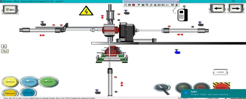
The main screen as demonstrated in Fig.6 comprises of a testing block, pusher cylinders, start button, emergency button, selection switch, alarms and section buttons. On pushing the start button the operation starts and on pushing stop buttons the operation stops respectively. When the emergency button is held down an alarm indicates on the screen showing the error message. Whenever a fault arises the alarm indicates and displays the troubleshooting actions to be performed. On hitting the push button section 1 it goes to the detailed working design of the testing machine.
Fig.6. Main SCADA screen for armature testing machine
The tools for drawing can be used from toolbox or from symbol libraries. The symbol libraries consist of inbuilt symbol functions which are assigned with a specific operation. The tool box consists of many tools with which we can create new symbols. Each symbol in the screen is assigned with a particular variable number depending on which it operates. This variable number is linked with the corresponding variable in the CX-programmer. Thereby whenever the plc program actuates the machine, the corresponding movement is obtained in SCADA. Each symbol consists of many properties which includes visibility, transparency, composed movement, scaling, rotation, background color, general attributes etc. If the symbol is to be activated whenever the variable is activated, visibility is enabled else it is disabled. The rotation indicates the inclination at which the object is to be placed. Apart from that, the background color and display properties can also be changed.
7
Fig.7. Working design of armature testing machineThe detailed working design of testing machine is demonstrated in Fig.7. In this process, the rotor is lifted up from the pallet and held tightly by the holder. The pusher cylinder keeps the rotor in a correct position. The indexing cylinder is used to rotate the rotor in the holder to the correct inclination. When the rotor is in correct position the armature testing block moves forward to measure the resistance. After measurement the block moves to original position and the rotor come down.
This screen consists of control switch which includes a start button, stop button, emergency button and selection switch. The push buttons indexing up, indexing down, testing forward, testing backward and pusher forward on the left bottom of the screen are used for manual operations. On activation of these switches the movement of corresponding cylinders takes place. Reed switches are placed along with eachcylinder to indicate the position of cylinders
either backward or forward and upwards or downwards. The right and left arrows are used to switch to the next page and previous page respectively.
7. RESULTS
The instrument trends in the Fig.8 illustrates the movement of each device in the armature testing machine. The toggle bar in the trend includes watch layer,project statistics,locals,scripts,project logic and local logic. The transition occurs from the value 0 to 1 as the component switches from idle mode to running mode and vice versa.The miscellaneous operations like rotor up down up,rotor up down down,rotor forward and rotor backward are marked with different colors.
Fig. 8. Trend showing cylinder movement
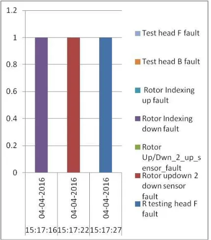
The Fig. 9 bring to light the fault occuring with each device. The time and date along the x axis is drawn against the values indicating off/on mode in y axis. The brief description of the corresponding componentfaults are also itemized in distinct colors.The faults can be of any devices like sensor,cylinder,piston,pusher or conveyor.The command on click symbol triggers the pop up screen which indicates instruments data screen.
Fig. 9. Graph indicating fault occurrence
The data logger screen shown in Fig.10 is in tied with real time SCADA screen. The alarm indicator in the main screen is executed as commands on click and when it is enabled to changes from home screen to data logger screen. This screen incorporates the
display of various parameters like event text, event time, user and description. Event text provides the description of the concurrent events occurring and also the malfunctioning event. The exact date and time of when the event has occurred is illustrated through event time. For example, the first event indicates that communication has established in station 1on 4thApril 2016 at 11:34 am. The alarm bell is the event describing the emergency situations where caution has to be taken. The last three events describes that rotor up down is not in proper position and also its description.
8. CONCLUSION
The on stream monitoring and inspection system is not often up satisfactory in an HMI system. As a result the advanced SCADA system has been designed to monitor all the machine operations taking place in the plant. All these processes are distributed throughout the plant thus making it a distributed control system. This system brings about accurate and repeated results all the time. Data will be chronicled at regular intervals of time. It also indicates the errors and thus helps in troubleshooting. The main distinguishing feature of this DCS architecture is that it does not obey a master-slave arrangement. All the PLCs in the quality inspection and maintenance line acts as its own master. Each plc unit is having access to the control station. Thus even if any PLC unit behaves inoperable it does not impinge the performance of other machines. A control workstation acts as the central hub which consists of a main SCADA screen where we can monitor all the operations, control the devices and analyze the performance of the system. The only constraint is in selecting the appropriate optional board which is compatible with each PLC.
Fig.10. Data logger screen
Acknowledgements
This project was undertaken under the guidance and support of Mr.Anand R ,Head of motor division,IFB Industries, Bangalore and Mr. Karmegham S, Maintenance head, IFB Industries,Bangalore. I express my gratitude towards Mr.Bagyaveereswaran V,associate professor,VIT University,Vellore for his stimulating guidance and constructive suggestions. Am also thankful to all my friends and my parents for their motivation and the moral support.
REFERENCES
[1] MaldarAmanMalikamber. “Implementing SCADA systems for industrial environment using IEEE C37.1 standard”.IEEE C37.1: IEEE Standard for SCADA and Automation Systems.
[2] MeghaAnand S.A, Suprathik
Sarkar,SreeRajendra, “Application of Distributed Control System in automation of Process Industries.” International Journal of Emerging Technology and Advanced Engineering. ISSN 2250-2459, Volume 2, Issue 6, June 2012 [3] A.V. Barenji, R.V. Barenji and B.L. Sefidgari.
“An RFID enabled distributed control and monitoring system for a manufacturing system.” IEEE International, IEEE 2013.
[4] Mandeep Kaur, Manjeet Sandhu, Neeraj Mohan and Parvindher S Sandhu. “RFID technology principles, advantages, limitations and its applications.” International journal of computer and electrical engineering Vol.3, No.1, February, 2011 1793-8163.
[5] Prof.Akram Hossain, “HMI Design: An Analysis of a Good Display for Seamless Integration between UserUnderstanding and Automatic Controls”, Purdue University, Calumet, American Society for Engineering Education, 2012.
[6] Vivek, M. Koshti, Sangeeta, M. Joshi. “Design of HMI for PLC based automation system management and control of production and logistics.”International Federation of Automatic Control Conference, 2007 Volume # 4,Part# 1. [7] John McCain and Russell Straayer, Data Comm.
for Business, Inc. “Optimizing SCADA Network Communications: An Overview of Metropolitan Wide SCADA Communications Options.” [8] A.A. Abed, A.A. Ali and N Aslam, “Building a
hmi and demo application of WSN based industrial control systems.”IEEE International, IEEE. Energy, power and control, 2010.
[9] Rajeev Kumar and M.L Dewal, “Multisupervisory control and data display.” International journal of computer applications, May 2010.
[10]D.J Gaushell and H.T Darlington, “Supervisory control and data acquisition.” IEEE International, Proceedings of IEEE Volume 75, Issue 12, 2005.
[11]M.B. Mollah and S.S Islam, “Towards
IEEE802.22 based scada system for future
distributed system.”IEEE International,
International conference on ICIEV, 2012.
[12]Xie Lu “Supervisory Control and Data
Acquisition System Design for CO2 Enhanced Oil Recovery.” Electrical Engineering and Computer Sciences University of California at Berkeley, 2014.