THE DEVELOPMENT OF ADSORBENT BASED NATURAL GAS STORAGE FOR VEHICLE APPLICATION
(PEMBANGUNAN STORAN GAS ASLI BERASASKAN PENJERAP BAGI KEGUNAAN KENDERAAN)
ASSOCIATE PROFESSOR DR. HANAPI BIN MAT ZAINAL ZAKARIA
TERRY GEORGE PAOU
DEPARTMENT OF CHEMICAL ENGINEERING
FACULTY OF CHEMICAL AND NATURAL RESOURCES ENGINEERING UNIVERSITI TEKNOLOGI MALAYSIA
ACKNOWLEDGEMENT
The financial support from the Ministry of Science, Technology and Innovation
(MOSTI) on the project (Project No. 02-02-06-0092/VOT 72229) is gratefully
ABSTRACT
THE DEVELOPMENT OF ADSORBENT BASED NATURAL GAS STORAGE FOR VEHICLE APPLICATION
(Keywords: Adsorptive gas storage, natural gas, adsorbent, zeolites, activated carbon)
Storage of natural gas by adsorption has a potential to replace Compressed Natural Gas (CNG) in mobile storage applications, such as in vehicles. Storage by adsorption at moderate pressure of 500 psig could be expected to reduce the problem of bulky high-pressure CNG storage within a confined space used in vehicle. In adsorptive storage, the amount of gas stored at lower pressure increases when a large portion of gas adsorbs on the adsorbent. However, its capacity and performance depend on adsorbent types and properties. This study is focused on the storage capacity and delivery performance of Adsorptive Natural Gas (ANG) storage employing different types of commercial adsorbents which were carried out by performing experimental work on an ANG storage system. Methane adsorptive storage was done in a 0.5-liter adsorbent-filled gas vessel under isothermal and dynamic conditions. The ANG vessel was charged with methane up to 500 psig at different rates of filling and was discharged under dynamic condition at a varied rate of discharge. The results show that the storage capacity obtained under isothermal condition is higher than under dynamic condition due to continuous temperature rise experienced during dynamic charging. Higher storage capacities were obtained for adsorbent with larger surface area and micropore volume but smaller interparticle void. Adsorbent that has high heat capacity and low heat of methane adsorption yields lesser temperature rise during adsorption and lesser temperature fall during desorption. Consequently, these characteristics lead to a better storage and delivery capacities. At faster charging rate, lower storage capacity was obtained and faster discharging rate caused inefficient gas delivery. Under cyclic operation, adsorbents performances deteriorate when adsorbent structure is gradually damaged under high-pressure operation. Among the adsorbents tested, palm shell activated carbon shows the highest storage and delivery capacity which are 87.4 V/V and 75.8 V/V respectively.
Key Researchers:
Associate Professor Dr. Hanapi Bin Mat Mr. Zainal Zakaria
Mr. Terry George Paou
Email: [email protected] Tel. No.: +607-5535590 Fax No.: +607-5581463
ABSTRAK
PEMBANGUNAN STORAN GAS ASLI BERASASKAN PENJERAP BAGI KEGUNAAN KENDERAAN
(Kata kunci: Storan gas berpenjerap, gas asli, penjerap, zeolit, karbon teraktif)
Storan gas asli secara penjerapan berpotensi untuk menggantikan storan gas asli termampat (CNG) bagi kegunaan kenderaan. Storan secara penjerapan bertekanan sederhana pada 500 psig boleh dimanfaatkan untuk mengatasi masalah saiz tangki gas asli termampat yang besar dalam ruang yang terhad pada kenderaan. Walau bagaimanapun, kapasiti dan prestasi penjerapan gas bergantung pada jenis and sifat-sifat bahan penjerap. Kajian ini tertumpu kepada kapasiti storan dan prestasi pengeluaran gas asli terjerap (ANG) menggunakan bahan-bahan penjerap komersil yang berlainan jenis dengan menjalankan eksperimen pada suatu sistem storan ANG. Storan secara penjerapan ini dilakukan dalam suatu bejana gas bersaiz 0.5 liter berisi bahan-bahan penjerap di bawah keadaan isotermal dan keadaan dinamik. Bejana ANG tersebut dipam dengan gas metana sehingga 500 psig pada kadar alir yang berlainan dan sistem tersebut pula dinyahpam pada keadaan dinamik dan pada kadar alir yang berbeza-beza. Keputusan eksperimen menunjukkan bahawa kapasiti storan dibawah keadaan isotermal adalah lebih tinggi daripada keadaan dinamik akibat kenaikan suhu yang berterusan semasa pengisian dinamik. Kapasiti storan yang lebih tinggi didapati untuk penjerap yang mempunyai luas permukaan dan isipadu liang mikro yang lebih besar serta ruang antara partikel yang lebih kecil. Penjerap yang mempunyai muatan haba tentu yang tinggi dan haba penjerapan metana yang rendah menunjukkan kenaikan dan penurunan suhu yang rendah semasa penjerapan dan nyahjerapan dan ini membawa kepada kapasiti storan dan pengeluran yang lebih baik. Pengisian dan pengeluaran gas pada kadar alir yang lebih tinggi pula menyebabkan kapasiti storan yang lebih rendah serta ketidakcekapan pengeluaran. Di bawah operasi berkitar, prestasi bahan-bahan penjerap telah merosot apabila strukturnya dirosakkan oleh tekanan storan yang tinggi. Di antara bahan-bahan penjerap yang digunakan, didapati bahawa penjerap karbon teraktif kelapa sawit mempunyai kapasiti storan dan pengeluran yang terbaik iaitu 87.4 V/V dan 75.8 V/V.
Penyelidik Utama:
Profesor Madya Dr. Hanapi Bin Mat Encik Zainal Zakaria
Encik Terry George Paou
Email: [email protected] No.Tel.: +607-5535590 No. Fax: +607-5581463
TABLE OF CONTENTS
CHAPTER ITEM PAGE
TITLE i
ACKNOWLEDGEMENT ii
ABSTRACT iii
ABSTRAK iv
TABLE OF CONTENTS v
LIST OF TABLES ix
LIST OF FIGURES xi
LIST OF ABBREVIATIONS xii
LIST OF APPENDICES xiii
CHAPTER I INTRODUCTION 1
1.1 General Background 1
1.2 Research Background 2 1.2.1 Introduction 2 1.2.2 Previous Research On ANG Storage 5 1.3 Problem Statement 7 1.4 Objective and Scope of Study 9
1.5 Report Outline 9 1.5 Summary 10
CHAPTER II ADSORBED NATURAL GAS STORAGE 11
2.2 Fundamentals of Adsorbed Natural
Gas Storage 15
2.2.1 Gas Adsorption 15
2.2.1.1 Theory of Gas Adsorption 16 2.2.1.2 Adsorption Isotherm 17 2.2.2 Adsorbent Materials 18 2.2.2.1 Adsorbents Properties 18 2.2.2.2 Adsorbents for Natural
Gas Storage 21
2.2.3 Mechanism of Natural Gas
(Methane) Adsorptive Storage 31 2.2.4 Factors Influencing The
Adsorption Capacity of
Natural Gas 32
2.2.4.1 Natural Properties of
Adsorbent and Adsorbate 32 2.2.4.2 Adsorbent Surface Area
And Pores 33
2.2.4.3 Adsorption Temperature 33 2.2.4.4 Packing Density
of Adsorbent 34
2.3 Concept of ANG Storage 35
2.3.1 ANG Storage Model 36 2.3.1.1 Charge (Filling) Phase 36 2.3.1.2 Discharge Phase 38 2.3.2 ANG Storage Operation Principle 40 2.3.3 ANG Performance Indicator 43 2.3.3.1 Storage Capacity 43 2.3.3.2 Delivery Capacity 46 2.3.4 ANG Performance Measurement 46
2.4.1 Natural Gas Composition 52 2.4.2 Heat of Adsorption 54
2.4.3 Isotherm Shape 58
2.5 Summary 59
CHAPTER III MATERIALS AND METHODS 61
3.1 Materials 61
3.2 Experimental Set-up 63
3.2.1 Lab-scale ANG Test Vessel 63 3.2.2 Measuring and Controlling
Equipment 66
3.2.3 Experimental Rig 66 3.2.4 Adsorbent Loading 69 3.3 Experimental Description 69 3.3.1 Experimental Procedures 72 3.3.1.1 Pre-adsorption 72 3.3.1.2 Isothermal Adsorption 73 3.3.1.3 Dynamic Adsorption
and Desorption 74
CHAPTER IV RESULTS AND DISCUSSION 76
4.1 Parametric Study 76
4.1.1 Charging Phase 77
4.1.1.1 Results of Different Type
of Adsorbents 77 4.1.1.2 Effect of Charge Flow
Rate 85
4.1.2 Discharging Phase 88 4.1.2.1 Results of Different Type
4.1.2.2 Effect of Discharge
Flow Rate 95
4.2 Storage Characteristic Study 98 4.2.1 Adsorption Isotherm 99 4.2.2 Dynamic of Gas Uptake
and Delivery 102
4.3 Cyclic Test 105
4.4 Summary 108
CHAPTER V CONCLUSION AND RECOMMENDATION 109
REFERENCES 111
LIST OF TABLES
TABLE NO. TITLE PAGE
2.1 Malaysian natural gas composition 12
2.2 Physical properties of commonly used adsorbents 20 2.3 Adsorptive properties of commonly used adsorbents 20 2.4 Typical applications of commonly used adsorbents in
chemical processes 22
2.5 Storage and delivery performance of carbonaceous
adsorbents in literature 28
2.6 Methane stored with different adsorbents 49
2.7 Cycling test results with pure methane 49
3.1 Surface properties of adsorbent materials used in ANG testing 62
3.2 Adsorbent thermal properties 62
3.3 Composition of methane used in ANG testing 63
3.4 Properties of methane 63
3.5 ANG test vessel specification 65
3.6 Measuring and controlling equipment 67
3.7 Loading weight and densities of adsorbents 69 4.1 Storage capacity of different types of commercial adsorbents
tested 78
4.2 Storage capacity of palm shell AC at different flow rates 86 4.3 Gas delivery performance of different type of commercial
adsorbents 90
4.4 Delivery capacity of palm shell AC at different flow rates 96 4.5 Isothermal storage capacity for each type of adsorbent tested 100 4.6 Storage and delivery capacity under cyclic operation 106 4.7 Delivery ratio of different type of adsorbents under cyclic
LIST OF FIGURES
FIGURE NO. TITLE PAGE
1.1 Comparison between CNG and ANG storage 4
2.1 Molecular structure of crystalline and amorphous solids 19
2.2 Pore structure of activated carbon 24
2.3 Granular activated carbon 26
2.4 Powder activated carbon 26
2.5 Pelleted activated carbon 26
2.6 Microscopic view of activated carbon packed bed 27
2.7 Zooming 1:10 of the packed carbon 27
2.8 Zooming 1:100 of the packed carbon 27 2.9 Methane adsorption on a graphite surface 32
2.10 Impact of packing density on adsorption and methane storage capacity 35
2.11 Simulation of ANG storage charge and discharge cycle 37
2.12 Methane adsorption isotherm on activated carbon 38
2.13 Methane adsorption storage versus compression storage 41
2.14 Different methods of methane desorption 42
2.15 Schematic of dynamic ANG test system 47
2.16 Adsorption isotherm for every hydrocarbon component by an activated carbon at 25 oC 53
2.17 Illustration of the impact of heat of adsorption on capacity during discharge 55
2.18 Axial temperature profile at the center of an ANG cylinder during discharge 56
cylinder at depletion 57 2.21 Characteristic of natural gas adsorption isotherm and
compression storage 58
3.1 Schematic diagram of ANG pressurized vessel 64
3.2 The ANG storage experimental rig 67
3.3 Schematic diagram of ANG test rig 68
4.1 Temperature behavior during adsorption 79
4.2 ANG storage pressure vs. gas uptake, bed temperature and time during dynamic charge 84
4.3 Adsorbents bed temperature profiles during charge at 1 l/min 86
4.4 Effect of charging rate on gas uptake 87 4.5 Adsorbents bed temperature profiles during charge 89
4.6 Adsorbents bed temperature profiles during discharge at 1 l/min 92
4.7 ANG storage pressure history during dynamic discharge 94
4.8 Pressure drop versus bed temperature and volume of methane during dynamic discharge 95
4.9 Effect of discharging rate on gas delivery 97
4.10 Bed temperature profile at different discharge flow rate 97
4.11 Methane adsorption isotherm on different type of adsorbents 101
4.12 Characteristic of ANG storage during charge and discharge 103
LIST OF ABBREVIATIONS
Al - Aluminum
ANG - Adsorbed Natural Gas
CNG - Compressed Natural Gas
CO - Carbon Monoxide
LEL - Lower Explosion Limit
LNG - Liquefied Natural Gas
MPa - Megapascal
NGV - Natural Gas Vehicle
NMHC - Non-methane Hydrocarbon
NOx - Oxide of Nitrogen
O - Oxygen
ppm - Part per million
psi - Pound per square inch (Ibf/in2)
psia - Pound per square inch of absolute pressure
psig - Pound per square inch of gauge pressure
Si - Silica
STP - Standard Temperature and Pressure
upm - Unit per million
LIST OF APPENDICES
APPENDIX TITLE PAGE
A1 Summary report of palm shell-derived activated carbon
adsorbent surface analysis 119
A2 Summary report of Darco activated carbon adsorbent surface
analysis 120
A3 Summary report of MS zeolites (powder) adsorbent surface
analysis 121
A4 Summary report of MS zeolites (beads) adsorbent surface
analysis 122
A5 Summary report of silica gel adsorbent surface analysis 123 B1 Experimental results of isothermal adsorption 124 B2 Experimental results of dynamic charging 126 B3 Experimental results of dynamic discharging 132 C Calculations of the amount of gas adsorbed on the
INTRODUCTION
1.1 General Background
Natural gas has been increasingly useful and important as fuel for combustion. Lately, natural gas was used promisingly as fuel for the internal combustion engine, i.e., as fuel for vehicle application. In this field, natural gas has advantages over other hydrocarbon fuels because it is more economical, offers a greater reduction in carbon monoxide (CO), nitrogen oxides (NOx), and non-methane hydrocarbon (NMHC) emissions while having a higher octane numbers – therefore a higher thermal efficiency than gasoline or diesel oil. In other words, it offers a cleaner combustion and a more efficient consumption.
Natural gas has been considered as a potentially attractive fuel for vehicle use. It is cheaper than gasoline and diesel. The wholesale price of natural gas in Malaysia is about RM0.55/liter compared to gasoline and diesel which is
liquefied at ambient temperature by pressurization because of its critical temperature, Tc , is -82.6 oC. Since it is a gaseous fuel, its volumetric energy content is low
compared with those of liquid fuels (Mota, 1999). In fact, natural gas outscores petroleum-based fuels in every aspect except onboard storage (Talu, 1992).
Currently, natural gas is compressed at pressures up to 25 MPa (3600 psi) in order to be stored compactly on-board and dispensed quickly. However, this storage method requires expensive and extensive high-pressure compression technology
(Jasionowski et al., 1989).
1.2 Research Background
1.2.1 Introduction
For vehicle application (in NGV technology), natural gas is usually stored in a 50 liter pressurized vessel (cylinder) at a very high pressure which is around 2500 – 3000 psi (17.2 – 20.7 MPa) (Mota et al., 1995) and is called Compressed Natural Gas (CNG). This high pressure, however, causes several drawbacks in the storage system (Elliott and Topaloglu, 1986):
• The energy densities achieved are approximately one quarter that of gasoline. The operational range of the vehicle is limited due to the awkward bulk of high-pressure cylinders which take up valuable cargo or trunk space.
• The fuel supply system compressors are complex and expensive. Three to four
compression stages are needed, resulting in high cost of maintenance and energy of operation.
• There is a perception of danger associated with the high-pressure systems as well
as some real potential problems, such as cylinder corrosion and the possible explosive release of compressed gas.
These are the main factors why natural gas has not been used widely for vehicle engine (Remick et al., 1984).
A large effort has been invested in the replacement of high-pressure
limit can be easily achieved with a single-stage compressor or, alternatively, the vehicle can be refueled directly from a high-pressure natural gas pipeline. In this way, a significant decrease in the capital and operating cost of compression stations is achieved (Mota, 1999).
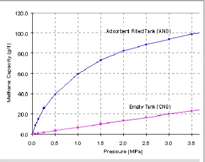
There is a new technology available to answer these difficulties of CNG storage. This technology is called Adsorptive Natural Gas storage or usually called Adsorbed Natural Gas (ANG). ANG storage is a technology in which natural gas is adsorbed by a suitable adsorbent material with high porosity. This storage of natural gas takes place at a relatively low pressure compared to CNG, which is around 500 psi (3.5 MPa), achievable by single-stage compression and can provide nearly the same capacity of CNG (Matranga et al., 1992). When natural gas is charged into a vessel packed with an adsorbent, the energy density stored will be greater than of the same vessel without adsorbent (empty vessel) at the same pressure and therefore, the amount that of natural gas that can be stored is increased. In an empty high-pressure storage tank, gas is forced into the tank - the more gas, the higher pressure. If someone puts some microporous materials into the tank, we can store the same amount of natural gas in the same tank, but at lower pressure (Gubbins and Jiang, 1997). There is a force exerted by carbon atoms inside the pore and this force attracts a lot of gas molecules into the pore so that the amount of gas in the bulk is reduced. As a result, collision between gas molecules in the free space within the tank
decreased and therefore, gas pressure is reduced while maintaining a high density of methane in the pores.
stored at lower pressure because the ANG vessel can be charged or pressurized with more gas, as the pressure is still low.
Figure 1.1: Comparison between CNG and ANG storage (Cook and Horne, 1997)
ANG system pressures of 500 to 600 psig allow designers to progress from the constraints of cylindrical-shaped containers currently used by CNG vehicles. Conformable tanks, similar to conventional gasoline tank, would not intrude upon or detract from on-board storage space. The capital and the operating cost of
compression and refueling equipment also have the potential to be lowered than the current CNG equipment. Moreover, the global warming potential for ANG is also reduced because less energy is required to compress natural gas, resulting in lower carbon dioxide emissions. From a safety and utilization perspective, lower ANG pressure may be more readily accepted compared to CNG (Cook and Horne, 1997).
1.2.2 Previous Research On ANG Storage
Adsorption storage is regarded as the most promising new low-pressure storage for natural gas (Remick and Tiller, 1985). Most research on ANG storage has aimed at the development and evaluation of economical adsorbents with storage capacities comparable to that of CNG. To date, the most promising adsorbents are highly microporous carbons with high packing density (Mota et al., 1997). In addition, other areas of study concerning the ANG storage are the laboratory test of an ANG storage system which includes ANG thermal behavior and management, large scale adsorption experiment, dynamics of ANG system, and demonstration of ANG storage vehicle application.
Meanwhile, Remick and Tiller (1985) had conducted ANG experiments to assess the magnitude of the impact of the heat of adsorption on storage capacity using a one-liter cylinder. A carbon adsorbent was used for this work and it had a total storage capacity of about 100 volumes per volume (V/V) of methane at 500 psi and a delivered capacity of about 80 V/V of methane in cycling from 500 psi to atmospheric pressure. The methane adsorption isotherms were performed for this carbon at both 25 oC and 90 oC for pressure from vacuum to 500 psi. The cylinder was charge and discharged in slow and rapid rates. The experiment were conducted under condition simulating both a slow fill, where carbon bed temperature would have time to cool down to ambient condition, and a fast fill where the carbon bed temperature rise rapidly. It was determined that rapid filling of an adsorption storage at ambient condition results in only 75% of the storage capacity that can be achieved by a slow fill rate. These quantitative results however, are specific for the carbon used here but nevertheless, the general pattern should hold true.
A more extensive study on ANG storage system was carried out by Sejnoha et al. (1996). Their study is focusing on optimisation of activated carbon storage capacity and on performing a large-scale test bench adsorption experiments. The test bench, using 71-liter storage tank, permits simulation of conditions expected in a vehicle, adsorption with thermal management, heavier hydrocarbon filtering from gas stream and re-odorization of desorbed gas. Thermal management systems for cooling on board and at the filling station are described and a model was developed for predicting breakthrough curves at various operating conditions for filter prototype design. They presented the difference between a slow-fill and a fast-fill mode in terms of temperature rise and storage capacity. They concluded that the use of thermal management during a slow-fill has a minimum effect upon increasing storage capacity. During a fast-fill, the temperature rise is significant and leads to storage capacity loss. For as little as 20 oC of temperature decrease, an increase storage capacity up to 15% can be obtained. The use of thermal management can effectively improve the storage capacity.
subject of charging rate of the storage system while given emphasis to thermal effects and hydrodynamics of flow through the carbon bed in order to develop a theoretical tools to provide an accurate description of the dynamics of ANG storage system. In order to study the influence of diffusional resistances, an intraparticle transport equation is added to the computational model. Also, they discussed the discharge process and proposed solutions for reducing the adverse effect of the heat of adsorption on storage capacity including in situ thermal energy storage. They concluded that taking vacuum as the initial condition for the charge cycle is
unrealistic and a more realistic condition would be certainly the exhaustion pressure used in the discharge cycles. ANG vehicles will have controlled discharge rates which are sufficiently low so that the pressure gradient in the tank can be completely neglected.
Cook and Horne (1997) have developed a high performance, yet low cost microporous adsorbent capable of delivering 150 V/V of natural gas from the storage. They have also designed and fabricated a conformable tank to store the fuel and adsorbent and equipped two vehicles with the ANG system to demonstrate their performance. The best performing material developed are derived from coconut shells and peach pits. The ANG tank developed was a 22-cell, rectangular design. The multi-cell tank design aids thermal management of the ANG storage. Both vehicles converted to the ANG system performed very well. Their performance and drivability are equivalent to a comparable gasoline models.
1.3 Problem Statement
should also be tested for natural gas adsorption besides currently used activated carbon. Even though highly microporous activated carbon has been reported as the most promisingly potential material as ANG storage adsorbent (Mota et al., 1997), but performance tests should also be imposed on other theoretically potential materials mention above to gauge how far they are reliable as alternatives for activated carbon.
Among the studies of ANG storage in the literature, most of them are
regarding the natural gas adsorptive behavior and storage condition, production of an economic carbon adsorbents, and adsorbents storage capacity development, while the viable aspect of this technology is the capability and reliability of the adsorbent-filled storage to discharge sufficient amount of gas for applications under realistic
operational condition (Chang and Talu, 1996). In view of this, it is vital to perform ANG tests for both adsorptive charge and desorptive discharge of natural gas on different types of adsorbents in order to know their storage delivery performance with respect to their storage capacity. In addition, it is also equally important to perform the ANG tests under cyclic operation to study the performance of the adsorbents for repetitive application; whether they are reliable for repeated and prolonged operation, as it should be for practical application.
charging phase (Matranga et al., 1992; Talu, 1992). Therefore, considering this disturbing effect, it is important to run the performance tests of ANG storage system under dynamic condition, a condition where pressure and temperature vary, to determine the actual amount of gas that could be delivered from the adsorbent-filled storage in evaluating their performance for practical application.
1.4 Research Objectives and Scopes
The objective of this study is to develop adsorbent based natural gas storage for vehicle application with special emphasize on determining the storage capacity of different types of commercial adsorbents as adsorption media for Adsorbed Natural Gas (ANG) storage and to evaluate their performance in delivering the stored gas.
This study includes measuring the amount of gas that could be stored and the amount of gas deliverable from the ANG storage, and studying the effect of charge and discharge rate. Eventually, this research would want to figure out the
characteristics of a reliable adsorbent, which will leads to a better methane storage capacity and delivery performance. The storage capacity of the commercial
adsorbents is measured with pressurization up to 500 psig under isothermal and dynamic condition while the gas delivery performance from the adsorbent-filled storage will be evaluated by discharging from 500 psig to atmospheric pressure under dynamic condition. Under dynamic condition, the ANG storage is charged and discharged at varied flow rates and storage temperature varies naturally. Terms and variables understudies are (1) behavior of storage temperature, (2) profile of storage pressure, (3) the adsorption/desorption characteristics, (4) methane storage and delivery capacity on different adsorbents, (5) dynamic efficiency of methane delivery, (6) effect of charge/discharge flow rates, and (7) cyclic behavior.
1.5 Report Outline
the objective of research described in section 1.4. This report contains five chapters which each chapter respectively containing its own introduction, descriptions of the relative topics and scopes to achieve the objectives of research and summary. Chapter I basically discussed about the entire project study, which contains general background, research background, problem statement, objectives and scopes of this study, report outline, and summary.
The historical and technical aspects of adsorbed natural gas storage including the fundamental aspects, and operating concept and problems associated with ANG storage are presented in Chapter II. All the materials and methods including equipments, chemicals, and experimental rig used are discussed in Chapter III.
Chapter 4 presents the detailed discussions of experimental results. The discussions include the performance evaluation of various parameters on charging and discharging, storage characteristic evaluation, and cyclic performance evaluation test. The conclusions and recommendations for future study are presented in Chapter V.
1.6 Summary
ADSORBED NATURAL GAS STORAGE
Natural gas is a gaseous mixture of light hydrocarbons which is found underground in sedimentary rock formations, often in the same location as crude oil. It is colorless, odorless fuel that burns cleaner than many other fossil fuels such as coal, gasoline, and diesel. Natural gas consists of mainly methane (85-95%) with a minor amount of ethane, and higher-order hydrocarbon compounds. Natural gas also contains a scant amount of unburned component such as carbon dioxide, nitrogen and sulfur. However, the percentage of natural gas composition is different from one reservoir to another (Parent, 1986). Natural gas composition from Malaysian reservoir is as presented in Table 2.1.
to give commercial natural gas a detectable odour. This is done to make gas leaks readily detectable at 20% of lower explosive limit (LEL) (Senatoroff and Forwalter, 1964). An undetected gas leak could result in an explosion or asphyxiation. Natural gas has a specific gravity ranging between 0.60 to 0.65. This characteristic is an advantage in handling natural gas because when natural gas leaks to the atmosphere, it tends to elevate since natural gas is lighter than air.
Table 2.1: Malaysian natural gas composition (Gas Malaysia Sdn. Bhd., 1995)
Volume Percentage
Natural Gas Component Before 1995 After 1995
Methane (CH4) Ethane (C2H6) Propane (C3H8) i-butane (C4H10) n-butane (C5H10)
Other hydrocarbons (C5+) Nitrogen (N2)
Carbon dioxide (CO2)
84.75 10.41 0.98 0.07 0.04 0.00 0.39 3.36 92.73 4.07 0.77 0.08 0.06 0.01 0.45 1.83
Total 100.00 100.00
Gross Calorific Value, CV (Kcal/Sm3) 9.583 9.253
Specific Gravity 0.65 0.61
2.1 Natural Gas Storage
Various approaches can be used to store natural gas, including compression, liquefaction, dissolution, and adsorption. Compression is the currently used fuel storage technique for natural gas vehicle. It is termed as Compressed Natural Gas (CNG). To reach a substantial capacity, very high storage pressures are used and are likely to increase the pressure up to 25 MPa (3600 psi). CNG relies on bulky, high-pressure vessels to store a quantity of natural gas that delivers about one-third (33%) of the range of an equal gasoline under typical operating conditions (Liss et al., 1992). Therefore, the storage tanks are heavy, expensive and unsafe. In addition, this storage method requires expensive multi-stage high-pressure compression facility for refueling (Matranga et al., 1992).
Conventionally, large-scale natural gas storage is by liquefaction, known as Liquefied Natural Gas (LNG). LNG provides nearly two-third (67%) of the range of a comparable volume of gasoline (Liss et al., 1992). In this method, natural gas is cooled to –164 oC (cryogenic temperature). LNG is liquefied via a cryogenic procedure, and then delivered to some staging area before it is delivered to a vehicle. This method requires an insulated storage vessel to stage the fuel. Thus, the cost of liquefaction, the special insulating vessels required and the potential fire hazard are such as to make it unsuitable for used on a small scale. The LNG cooling requirement is inconvenience to its use as a fuel. Maintaining the cryogenic temperature involves increased insulation and a need for occasional venting of the fuel to the atmosphere, or to a vent recovery system as a means of controlling the fuel temperature. This storage technique is not suitable for vehicle application because it place extreme conditions on the tank for a vehicle (Horstkamp et al., 1997).
mechanism are required. In addition, lower pressures and higher energy densities of the solutions could be outweighed by cost of the solvents required to make the solutions and the additional energy for cooling if necessary (Horstkamp et al., 1997).
Another alternative to store natural gas especially for vehicle application is the Adsorbed Natural Gas (ANG) storage system at low pressure. ANG storage operates by using a microporous material – an adsorbent – which is loaded into the storage container of the natural gas. When the cylinder is pressurized with natural gas, a large portion of fuel adsorbs on the carbon lowering the storage pressure (Remick and Tiller, 1985). Due to strong enhancement of adsorption potential in the micropores, the density of the adsorbed phase can be higher than that of liquid natural gas. In general, when a storage vessel filled with an adsorbent is used to store natural gas, the storage pressure is reduced to around 500–600 psi. This pressure is relatively low compared to the CNG storage which is around 3000 psi. The ANG storage stored 67% of the total amount storable with the same storage vessel without adsorbent due to the storage space taken up by adsorbent mass but at 1/6 of its pressure (Cook and Horne, 1997). This technology is also known as Low Pressure Adsorbed Natural Gas in which substantial amount of gas is storable at relatively low gas storage pressure.
2.2 Fundamentals of Adsorbed Natural Gas Storage
The foundational study of ANG storage involves the topics of gas adsorption in general, the characteristics of a suitable adsorbent material, the mechanism of natural gas adsorption on the adsorbent and some factors that influence the adsorptivity. The insight on these fundamental subjects will give better understanding regarding the ANG underlying characteristics.
2.2.1 Gas Adsorption
The term adsorption is generally used to denote the enrichment of one or more components in an interfacial layer between two bulk phases. In dealing with adsorption at gas/solid interface, it is customary to call the material in the adsorbed state the adsorbate, and to refer to the same species in the bulk gas phase as the adsorptive. The adsorbing solid is called adsorbent (Parfitt and Sing, 1976).
The amount of gas adsorbed, term as x, per gram of solid depends on pressure, p, temperature, T, the specific surface area, S, and the porosity of the adsorbent, and also on the nature of the gas-solid system as shown in Equation 2.1:
x = f (p, T, S, porosity, system). (2.1)
For a given gas adsorbed on a given solid at a constant temperature, Equation 2.1 simplifies to
x = f (p)T , (2.2)
or if the gas is below its critical temperature, Equation 2.1 simplifies to
x = f (p/po)T , (2.3)
The nature of the adsorbing surface is a determining factor in adsorption. To be useful as an adsorbent, a solid must present a large surface area per unit mass (up to 1500 m2/g) (Rodrigues, 1989). This can only be achieved with porous solids such as activated carbon, silica gel, aluminas, and zeolites, which contains many cavities or pores with diameters as small as a fraction of a nanometer. Surfaces of such solids contain sites of particular attraction for adsorbing molecules. If the sites are close together, the adsorbed molecules may interact with one another, if they are sufficiently dispersed, the adsorbed molecules may interact with the sites. Depending upon the strength of the forces binding them to the sites, these adsorbate molecules may be mobile or fixed in its position (Smith et al., 1996).
2.2.1.1Theory of Gas Adsorption
The surface of a solid has a tendency to attract and to retain molecules of other species (gas or liquid) with which such surface come in contact. This phenomenon of surfaces is termed as adsorption. It denotes the taking up of gases, vapor, or liquid by a surface or interface (Gurdeep, 1977). It is a property of a solid to retain on, or concentrate at its surface, one or more components (atoms, molecules, or ions) from another liquid or gas in contact with the surface. Adsorption is a characteristic surface or interface phenomenon, a fundamental physico-chemical property of solids. Adsorption phenomena are operative in most natural physical, biological, and chemical systems, and adsorption operations employing solids such as activated carbon and synthetic resins are used widely in industrial applications and for purification of waters and wastewaters (Slejko, 1985).
adsorption process must always be exothermic or heat releasing (Parfitt and Sing, 1976). Adsorption of gas molecules into pores on adsorbent surface will release some amount of heat called Heat of Adsorption. In ANG storage context, the heat of methane adsorption is approximately 4 kcal per mole (Golovoy, 1983).
Based on the nature of the forces between the gas and the solid surface, gas phase adsorption are categorize into two types, which are physical adsorption and chemical adsorption. If the physical attraction forces hold the gas molecules to the solid, the adsorption is called physical adsorption (physisorption). Physisorption is a phenomenon where gas or vapor molecules were adsorbed by an adsorbent without any chemical reaction. Physisorption is cause mainly by London Dispersion Forces, a type of Van der Waals Force, which exist between molecules, and the electrostatic forces between adsorbate molecules and the atoms which composes the adsorbent surface. These forces act in a similar way to gravitational forces between planets.
If the chemical forces hold the gas molecules to the surface of the adsorbent, the adsorption is called chemical adsorption (chemisorption). In chemisorption, chemical reaction occurs between gas molecules and adsorbent surface area. Heat of adsorption released via chemisorption is greater than of physisorption. Chemisorption only occur at temperature more than 200 oC to reach the activation energy requirement to form or break chemical bond during adsorption or desorption process. It involves electron transfer between adsorbent and the adsorbates. The adsorbates will loss its electrons to the adsorbent and became positive ion. Adsorbent, on the other hand, becomes negative ion. With this the adsorbates will get attracted to the adsorbent surface. Reversibly, adsorbates will be desorbed from the adsorbent surface when the adsorbent release ions unto gas molecules.
2.2.1.2Adsorption Isotherm
further net adsorption occurs (Slejko, 1985). The common manner to depict this distribution is to express the amount of gas adsorbed per unit weight of the adsorbent, as a function of pressure at constant temperature, which is called Adsorption Isotherm. Adsorption isotherm is useful for describing adsorption capacity to facilitate evaluation of the feasibility of this process for a given application and for selection of the most appropriate adsorbent. Moreover, the isotherm plays a crucial functional role on predictive modelling procedures for analysis and design of adsorption systems. It is also useful for theoretical evaluation and interpretation of thermodynamics parameters, such as heat of adsorption.
2.2.2 Adsorbent Materials
Adsorbent is a substance that having a molecular structure that allows smaller molecules to penetrate its surface area and be kept inside the pores between its molecules. A large surface area of an adsorbent is a primary determinant for providing large adsorption capacity. Adsorption of natural gas on adsorbent follows pore-filling mechanisms and therefore the adsorption is dependent on the pore shape and volume. A useful adsorbent for ANG storage is a material that has pores of a suitable size to admit, hold, and discharge individual gas molecules.
2.2.2.1Adsorbents Properties
Adsorbent material can be categorized according to their molecular structure. In general, the molecular structure of an adsorbent can be divided into (a) crystalline and (b) amorphous, solid structure (Webster, 1999). Examples of a crystalline solid are molecular sieve zeolites while carbonaceous material is an amorphous one. The molecular structure of crystalline and carbonaceous solid is shown in Figure 2.1.
Figure 2.1: Molecular structure of (a) crystalline and (b) amorphous solids (Webster, 1999)
surfaces bounding the extensive pores and capillaries of highly porous solids (Slejko, 1985). A large specific surface area is preferable for providing large adsorption capacity. Larger surface area will allow more contact between gas molecules and adsorbent surface area to give way to more adsorption to take place. For example, activated carbon is one of the most widely used porous adsorbents because of its large surface area and capability of adsorbing a broad range of different types of adsorbates.
The performance characteristics of adsorbents relate in large measure to their intraparticle properties (Slejko, 1985). Surface area and the distribution of area with respect to pore size generally are primary determinants of adsorption capacity. The nature of the intraparticle surface area also markedly affects the types of adsorption interactions for an adsorbent. The effective adsorption capacity depends on the distribution of area or volume with pore size, and the distribution of molecular sizes to be adsorbed. Although not directly affect adsorption capacity, hardness or durability of individual adsorbent particles is an important property to be considered, at least for granular types of adsorbent application. This property largely determines the losses which occur on each adsorption cycle as a result of attrition during handling.
differently even if they are made from the same basic substance (Spang, 1997). Among the most commonly used microporous, high specific area materials in chemical process are alumina, silica gel, zeolites molecular sieves, active carbon, carbon molecular sieves, clays and polymers. The typical physical and adsorptive properties of the most commonly used adsorbent are summarized in Table 2.2 and Table 2.3.
Table 2.2: Physical properties of commonly used adsorbents (Spang, 1997)
Material Internal porosity (%) Average pore diameter (nm) Pore volume, micropores (cm3/g)
Pore volume, macropores (cm3/g)
Activated carbon 60 - 80 2 - 4 0.30 - 0.50 0.50 - 1.10 Silica gel 40 - 50 2 - 5 0.30 - 0.45 0.05 - 0.10
Activated aluminas 35 - 40 3 - 5 0.40 0.10
Molecular sieves 30 - 40 0.3 – 1.0 0.25 - 0.30 0.30 - 0.40 Polymer resins 40 - 50 9 - 10 0.05 - 0.20 1.2 - 1.5
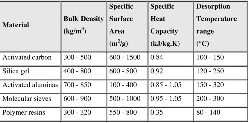
Table 2.3: Adsorptive properties of commonly used adsorbents (Spang, 1997)
Material Bulk Density
(kg/m3)
Specific Surface Area (m2/g)
Specific Heat Capacity (kJ/kg.K) Desorption Temperature range (°C)
Activated carbon 300 - 500 600 - 1500 0.84 100 - 150 Silica gel 400 - 800 600 - 800 0.92 120 - 250 Activated aluminas 700 - 850 100 - 400 0.85 - 1.05 150 - 320 Molecular sieves 600 - 900 500 - 1000 0.95 - 1.05 200 - 300 Polymer resins 300 - 320 550 - 800 0.35 80 - 140
Adsorption phenomena are operative in most natural physical, biological, and chemical systems. Adsorption operations employing microporous, high surface area solid adsorbents such as activated carbon, zeolite molecular sieves, alumina, silica gel and synthetic resins are widely used in industrial applications and for purification of water and wastewater (Suzuki, 1990). The typical applications of the most commonly used microporous adsorbents in chemical processes are summarized in Table 2.4.
2.2.2.2Adsorbents for Natural Gas Storage
Adsorbent that is useful to adsorb the natural gas in ANG storage is a substance that having a molecular structure that will allow methane (dominant component in natural gas) molecules to penetrate its surface area and be kept inside the pores between its molecules, in which pore filling adsorption mechanism takes place. The pore sizes in the adsorbent solid must be of a suitable size to admit, hold, and discharge individual gas molecules. If the pores are too small, the gas cannot be admitted. If they are too large, too many molecules of gas are admitted, and they display the characteristics of gas under pressure: frenzied movement, and constant molecular collisions (Brown, 1995). This means that they cannot be packed as tightly as if they were held nearly immobile in an adsorbent structure. There are some material that fit these characteristics such as activated carbon, zeolites, silica gel and molecular sieves.
and the amount adsorbed at 3.5 MPa (500 psig), as close as possible to 1 (Parkyns and Quinn, 1995).
Table 2.4: Typical applications of commonly used adsorbents in chemical processes (Suzuki, 1990)
Type of Adsorbent Typical Application
Alumina
Silica Gel: Grade 03
Grade 11, 13
Grade 40
Various Types Zeolites Molecular Sieves:
High-strength 3A
4A
5A
13X
Activated Carbon
Synthetic Resin
Drying process
Drying process
Dehydration of natural gas and industrial gases
Miscellaneous dehydration application where fine particle size is preferred
Liquid and gas dehydration, hydrocarbon recovery
Gas and liquid separation, drying process
Use for cracked gas application for long life and low pressure drop
Use for most gas dehydration application in removing H2O and CO2
Pressure swing adsorption of hydrogen purifier
Removal of CO2 and impurities in butane isomerizers and air pretreatment application
Gas and liquid separation, guard beds
Purification of waters and wastewater
adsorbent rarely employed for ANG storage are molecular sieve zeolites and hydrophobic silica xerogel (Cracknell et al., 1993; Menon, 1997).
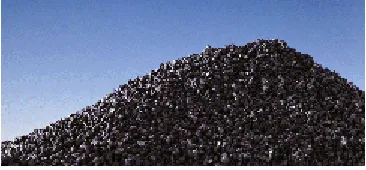
According to the research made by the Atlanta Gas Light Adsorbent Research Group (ARLARG) (1997), the best performing materials developed thus far are derived from organic materials including coconut shells and peach pits. These materials have a naturally occurring pore structure that can be optimized for the adsorption of the methane in natural gas. The method of densifying or compacting the adsorbent is also critical to achieving acceptable performance. Proprietary densification techniques were developed during the course of the research to form solid carbon monoliths and briquettes that match the profile of the tank for easy insertion.
A. Activated Carbonaceous Adsorbent
Base on previous study, for ANG storage, adsorbent material made of carbon has been found out to be the best one to store the natural gas molecules compare to the other materials. According to Parkyns and Quinn (1995), microporous activated carbon has emerged to be the best adsorbents for ANG storage. Microporous carbons are effective adsorbents for methane and are superior in this respect to molecular sieve zeolites (Barton et al., 1986 and Cracknell et al., 1993).
less than the storage capacity because carbon retains some gas at the exhaustion pressure. The maximum delivered capacity of ANG is 195 Vm/Vs for monolithic carbon and 137 Vm/Vs for pelletized carbon, compared to 216 Vm/Vs for CNG. However, in spite of the simulated capacities obtained, the highest experimental values obtained to date are 86 Vm/Vs for granular AX-21 activated carbon and 125 Vm/Vs for a monolithic carbon (Quinn, 1990).
Activated carbon is a crude form of graphite. From a chemist's perspective, activated carbon is an imperfect form of graphite. This imperfect structure results in a high degree of porosity and more than million-fold range of pore sizes. Porosity is what distinguishes activated carbon from other carbon substances and makes it "activated". The graphite structure gives the carbon its very large surface area which allows the carbon to adsorb a wide range of compounds. Figure 2.2 shows the pore structure of an activated carbon.
Figure 2.2: Pore structure of activated carbon (Brown, 1995)
1. Pores with widths not exceeding 2 nm are called micropores. 2. Pores with widths within 2 and 50 nm are called mesopores. 3. Pores with width more than 50 nm are called macropores.
The micropores represent at least 95% of the active internal sorptive area of the carbon (Jonas, 1987). The macropores and the mesopores play the role to conduct the adsorbate gases to the active site in the micropores. If an activated carbon contained only micropores, the probability of obtaining a high efficiency in adsorptive behavior of the carbon would be low because high pressures are required to force the gaseous fluid through a small diameter. Thus, the presence of the macropores is sufficient to permit easy entry of the gas molecules, from which they migrate by momentum and diffusion through the mesopores, and finally to the micropores where they are strongly bound by the London dispersion forces in a physical adsorption bond (Jonas, 1987).
Figure 2.3: Granular activated carbon (Chemiviron, 1998)
Figure 2.4: Powder activated carbon (Chemiviron, 1998)
Figure 2.5: Pelleted activated carbon (Chemiviron, 1998)
Figure 2.6 shows a view of a packed bed activated carbon while Figure 2.7 and Figure 2.8 show a microscopic view of it. A bed of an activated carbon is consisted of carbon granule, void fraction and pores with different shapes and sizes. The volume void fractions of a packed bed of activated carbon granules are the spaces between granules. The different types of pores are the macro-, meso-, and the micropore system of the carbon which was developed as a result of the activation process.
Figure 2.6: View of activated carbon packed bed (Chemiviron, 1998)
Figure 2.7: Zooming 1:10 of the above packed carbon (Chemiviron, 1998)
Table 2.5: Storage and delivery performance of carbonaceous adsorbent in literature
PERFORMANCE ADSORBENT
Storage Capacity (Vm/Vs)
Delivery Capacity (Vm/Vs)
REFERENCES BPL Commercial Activated Carbon Pelletized Carbon from Oxidized IBC-106 Coal
Peach Pit and Coconut
Shells derived Activated Carbon
Activated Carbon Fiber (ACF) from CO2 activation
KOH activation MCB-48M Carbon Powder
AX-21 Commercial Activated Carbon: Granule Mixture with polymeric binder CNS Commercial Activated Carbon: Granule Mixture with polymeric binder G126 Activated Carbon
PVDC derived Carbon 72 83 - 163 174 101 144 82 103 100 92.2 - -
164 at 500 psig 143 at 600 psig
143 at 500 psig
161 at 500 psig
-
-
-
-
80 at 500 psig
68 at 500 psig
Abadi et al. (1995)
Abadi et al. (1995)
Cook and Horne (1997)
Alcaniz et al. (1997)
Chen et al. (1997)
Sejnoha et al. (1994)
Sejnoha et al. (1994)
Remick And Tiller (1985)
B. Zeolites Adsorbent
There have been a number of experimental studies of the feasibility of using already existing materials for methane storage. Among these materials are zeolites (Cracknell et al., 1993; Jiang et al., 1994). The zeolites structures contain (-Si-O-Al-) linkages that form surface pores of uniform diameter and enclose regular internal cavities and channels of discrete sizes and shapes, depending on the chemical composition and crystal structure of the specific zeolites involved. Its significance as commercial adsorbent depend on the fact that in each of the crystals containing interconnecting cavities of uniform size, separated by narrower openings, or pores, of equal uniformity (Trent, 1995). Pore sizes range from about 2 to 4.3 angstroms.
Zeolites are crystalline hydrated aluminosilicates, of the alkali and alkaline earth metals. Their crystalline framework is arranged in an interconnecting lattice structure. The arrangement of these elements in a zeolites crystal creates a porous framework silicate structure with interconnecting channels of various sizes. This structure allows zeolites to perform gas adsorption, which is the ability to selectively adsorb specific gas molecules consistently within a broad range of chemical and physical environments.
The adsorption functions of zeolites are accomplished when gas molecules of different sizes are allowed to pass through the channels, and depending upon the size of the channel are separated, in a process known as molecular sieving. The ability of activated zeolites to adsorb many gases on a selective basis is in part determined by the size of the channels ranging from 2.5 to 4.3Å (0.25 to 0.43 nm) in diameter (according to zeolite type) (Trent, 1995). Specific channel size enables zeolites to act as molecular gas sieves and selectively adsorb such gases as ammonia, hydrogen sulfide, carbon dioxide, sulfur dioxide, water vapor, oxygen, nitrogen, and others.
methane molecule is 0.32 nm (Trent, 1995; Elliott and Topaloglu, 1986). This fact shows that zeolites are capable for methane adsorption in which methane molecules could penetrate through its surface and fill the microporous channels within zeolites substrates.
A work by Cracknell et al. (1993) has established a comparison discussion for both zeolite (assumed to have cylindrical pores) and carbon (assumed to have slit pores) for the advantage of storing methane from Grand Canonical Monte Carlo (GCMC) simulation for different pore sizes at 213 and 274 K have been also discussed. Their results suggested that an optimized pores of porous carbon is a more suitable material for adsorptive storage of methane than an optimised zeolite pores. The best pore size to use depends on the operating conditions of the system. They found that for a storage pressure of 3.4 MPa (500 psi) at 274 K the model slit carbon pore yields 166 g/l (methane adsorbed) compared to 53.1 g/l for the zeolite. Reduction in temperature does allow a greater amount of methane to be adsorptively stored for a given pressure.
C. Silica-Gel Adsorbent
2.2.3 Mechanism of Natural Gas (Methane) Adsorptive Storage
Intermolecular attraction in the smallest pores result in adsorption forces. This attraction is a type of Van der Waals force called London Dispersion Force. The adsorption forces works like gravity, but on molecular scale. They cause precipitation, in which adsorbates are removed from vapor stream. To develop a strong adsorption force, either the distance between the adsorbent platelets and the adsorbates must be decreased (by reducing its pore size), or the number of atoms in the solid structure must be increased (by raising the density of the carbon).
In a conventional high-pressure storage tank, such as a propane tank used for cooking, gas is forced into the tank - the more gas, the more pressure. If someone puts some microporous materials into the tank, we can store the same amount of natural gas in the same tank, but at lower pressure (Gubbins and Jiang, 1997). Using the Connection Machine CM-2 at Pittsburgh, Gubbins and Jiang simulated how parallel layers of carbon atoms can adsorb methane atoms. There is a force exerted by the carbon atoms inside the pore and this force attracts a lot of gas molecules into the pore so that the amount of gas in the bulk is reduced. As a result, the pressure of the tank can be kept low while maintaining high density of methane in the pores.
The optimal pore size that Gubbins and Jiang discovered is the width between two methane molecules. After the first layers of methane atoms line up along the pore's sides, carbon's attractive forces fall off rapidly. Thus, the adsorbed methane that are not in the contact layer on the wall will be much less tightly adsorbed because he forces will be much weaker. A rough analogy might be iron fillings attracted to the pole of a magnet. The first one or two layers will be tightly bound to the surface, and subsequent layers will be more loosely bound and less dense.
carton. At increased pressure (right side), the methane pack more closely and no longer sit over the hexagon centers.
Figure 2.9: Methane adsorption on a graphite surface (Gubbins and Jiang, 1997)
2.2.4 Factors Influencing The Adsorption Capacity of Natural Gas
The adsorption capacity of natural gas on an adsorbent depend upon several factors such as the properties of adsorbent and adsorbate, the adsorbent surface area and pores, temperature of the adsorption process and packing density of the adsorbent loading into the ANG vessel.
2.2.4.1 Natural Properties of Adsorbent and Adsorbate
behavior (Spang, 1997). Activated carbonaceous adsorbent, having greater measure of surface area and better porosity, will give higher storage capacity.
2.2.4.2 Adsorbent Surface Area and Pores
Efficiency of an adsorbent to adsorb gas depends on its surface area. Surface area, in turn, depends on the pore size. Macropores did not play important role in adsorption. They only serve as to give route for gas molecules to reach smaller pores that are micropores. Micropores, mainly formed during activation process, are very important for natural gas adsorption. This is because micropores structure is the most effective area to store gas molecules such as natural gas, which mostly consist of methane. Micropores typically range from less than 2 nm while methane molecule size is 0.32 nm (Elliot and Topaloglu, 1986). Therefore, possibility for all methane to be adsorbed is high. Generally, microporous activated carbon is having typical surface area range from 600 m2/g to 1200 m2/g (Rodrigues et al., 1989). Van der Waals force of the micropores is greater than of the mesopores and macropores. In addition, larger surface area will allow more contact between gas molecules and adsorbent surface area to give way to more adsorption to take place, in other words, more surface area, more pores.
2.2.4.3 Adsorption Temperature
A + S A – S + heat (2.4)
Above is the reaction for adsorption and desorption where A is adsorbate (natural gas) and S is adsorbent surface. When natural gas is adsorbed, heat of adsorption is released. When heat increases, reaction system will transfer the equilibrium to the left side and causing more gas molecules not to be adsorbed and subsequently reduces adsorption capacity.
2.2.4.4 Packing Density of Adsorbent
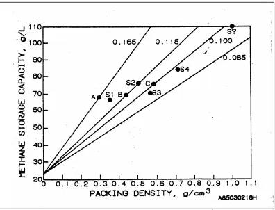
Packing density is defined as the mass of settled material per unit volume of storage space (Remick and Tiller, 1985). It is one of the critical parameters associated with the adsorbent storage of the natural gas. Though the adsorbents may indicate a high adsorbency on a mass basis, the low packing density means that much of the potential advantage is lost and the volumetric energy densities are still low. A carbon adsorbent with a mediocre surface area but a high packing density may actually store more methane, when loaded into a cylinder, than a high surface area carbon with a low packing density. For example, CECA carbon has a surface area of 1030 m2/g and a packing density of about 0.56 g/cm3. Nuchar WV-B, on the other hand, has a surface area of about 1600 m2/g but a packing density of only 0.30 g/cm3. When both carbons were loaded into a 1-liter cylinder and pressurized with methane to 3.6 MPa, the CECA carbon delivered 51.4 grams when discharged to atmospheric pressure while the Nuchar carbon only delivered 41.1 grams (Remick and Tiller, 1985).
data point for the 25% GX-32 and 75% Saran composite, and point S4 is for 100% Saran. Furthermore, Barton et al. (1984) have proposed that it may be possible to obtain a packing density as high as 1.0 g/cm3 for the Saran carbon. This point is plotted as S in the figure.
Figure 2.10: Impact of packing density on adsorption and methane storage capacity (Remick and Tiller, 1985)
2.3 Concept of ANG Storage Operation
depressurization of the storage from 500 psig back to the atmospheric pressure to remove the stored gas. ANG storage operates by enhancing the amount of gas stored when a large portion of gas adsorbs on the adsorbent and markedly improve the storage capacity at lower pressure. The ANG storage amount is measured with two capacity measures, which are the storage capacity and the delivery capacity. In the literature, ANG capacity measurements have been carried out by performing natural gas charging and discharging test on an adsorbent-filled pressurized vessel of different scales and experimental variations.
2.3.1 ANG Storage Model
ANG storage is modeled as series of consecutive cycles. Series of consecutive cycles means that the charging and discharging process of the natural gas from ANG storage is done repeatedly. Every cycle involves two steps. The first step is the filling of gas with a fixed composition gas mixture followed by the second step which is the discharging of gas at constant molar flow rate until the original storage pressure is achieved (Mota, 1999). Figure 2.11 shows schematic of the cycle. The two steps of this cycle series, which are filling phase and discharging phase of natural gas from storage, occur at P1 (initial pressure inside container before charging, 1 atm) and P2 (charging pressure of natural gas into storage, 3.5 atm).
2.3.1.1 Charge (filling) Phase
lowest. This means that adsorption capacity will reduce with temperature elevation. Charging of the natural gas into ANG storage can be achieved by several ways.
Figure 2.11: Simulation of ANG storage charge and discharge cycle (Mota, 1999)
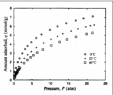
Figure 2.12: Methane adsorption isotherm on activated carbon (Chang and Talu, 1996)
2.3.1.2 Discharge Phase
Discharging of the natural gas from its storage container is actually a depressurization of natural gas unto depletion pressure, which is the minimum pressure to discharge the gas from the ANG container, normally at 14.7 psig under natural condition. For actual vehicular application of ANG storage system, discharge flow rate will be determined by the engine power demand. During this phase, some assumptions are made (Mota, 1999):
• Pressure inside container is uniform.
• Temperature of gas and particles is uniform along cylinder (container).
From the literature, it was found out that the heat consumed for desorption is only partially replaced by the wall thermal capacity and by the heat transferred from the surrounding (Chang and Talu, 1996). Consequently, drastic temperature fall occurs inside the storage vessel as the heat of the system is used up for desorption process. This phenomenon is more dominants at the center part of the cylindrical container.
Theoretically, as the storage container is always being refueled with the same gas mixture (fixed composition), the storage system will approach a steady-state cycle after it operates for an extended period of time. At this state, charge capacity will be equal to the discharge capacity, i.e., the natural gas stored are fully deliverable for use during discharge (Mota, 1999). At steady-state cycle, amount of species i discharged is defined in Equation 2.5.
Qi = zi Q(∞) (2.5)
where,
Qi = amount of species i discharge
Q(∞) = total amount of gas delivered at steady state zi = mole fraction of species i supplied
The discharge performance of the ANG storage system is determined from the dynamic efficiency of gas delivery. Dynamic efficiency is the ratio of the amount of gas discharged under dynamic (real) condition over that at isothermal condition as shown in Equation 2.6:
Dynamic efficiency, η=
condition isothermal
at Q
condition dynamic
at Q
i i
(2.6)
amount of gas discharged equal with the amount of gas charged to the container. There is a drastic reduction in the net delivery capacity of natural gas with cyclic operation. The leveling off of delivered capacity was observed when the cyclic testing was prolonged sufficiently (Parkyn and Quinn, 1995). The loss in the net deliverable capacity is 10% more when operates at non-isothermal condition (Mota, 1999).
When the discharge rate of the natural gas is held constant (constant molar flow rate), discharge duration (period) decreases with cycle number due to the reduction in the storage capacity causes by gradual filling of micropore volume with higher molecular weight hydrocarbon (Mota, 1999). Heavier species tends to remain adsorbed at depletion pressure during discharge phase. This impact of composition also occurs for other carbonaceous adsorbent and other mixture of natural gas composition.
2.3.2 ANG Storage Operation Principle
Gas storage by adsorption is carried out by using the micropores of the microporous adsorbent to enhance the density of the stored gas. The first thing to consider in performing this method is that if the introduction of the adsorbent is beneficial when compare with compressed gas. Figure 2.13 schematically shows this matter. The amount adsorbed increases with increasing storage pressure, and so does the amount stored by compression. If the storage pressure is higher than pC, then compression is better than adsorption. However, at lower pressures, adsorption is better than compression and the introduction of adsorbent can markedly improve the capacity. It is in this pressure range that adsorbed gas has its advantage.
then desorbed for use, the most relevant parameter is the delivered capacity that will determine the fuel supply and the energy produced.
Figure 2.13: Methane adsorption storage versus compression storage (Cook and Horne, 1997)
Generally, if the storage capacity at the storage condition is VS and is VD at the delivery condition, then the delivered capacity is the difference between VS and VD as shown in Equation 2.7:
VDEL = VS - VD (2.7)
where,
VDEL= delivered capacity
VS = storage capacity at the storage condition VD = storage capacity at the delivery condition
Pressure
Adsorbed gas Compressed gas
Amount adsorbed
Figure 2.14: Different methods of methane desorption (Cook and Horne, 1997)
Suppose that the gas is adsorbed in the adsorbent at temperature TL and pressure pS, then there are a few theoretical ways to deliver the adsorbed gas:
1. Pressure swing desorption. The system is kept at the temperature TL, but the pressure is lowered to pD to allow the delivery of the adsorbed gas. In this case, the delivered capacity will be the storage capacity at pS minus the storage capacity at pD, i.e.,
VDEL = VS1-VS3.
3. Combined temperature and pressure swing desorption. The pressure is lowered to pD and the system is heated to a higher temperature TH to deliver the adsorbed gas and the delivered capacity is VDEL = VS1-VS4. The combined process gives the highest capacity. However, the second method is probably not practical in vehicular application while the combination method is yet to be reported in the research papers.
2.3.3 ANG Performance Indicator
The capability and performance of ANG storage is measured in two capacity indicators, which are the storage capacity and the delivery capacity. The storage capacity is a measure of the amount of gas that could be stored in the adsorbent-filled cylinder while the delivery capacity depicted the amount of gas that is deliverable from the storage during discharge. The amount of gas deliverable from the storage during discharge is always lesser than the amount storable due to the retention of some amount of gas which result from factors such as heat of desorption and natural gas composition.
2.3.3.1Storage Capacity
Vs = ms/ρs (2.8)
where,
ms = amount of adsorbent in V ρs = real density of the adsorbent
Therefore, the amount of non-adsorbed gas inside the container is defined by Equation 2.9.
ρgVd = ρg(V – ms/ρs) (2.9)
where,
ρg = molar gas density at P and T considered
The total amount of gas, M, contained in the volume V is the storage capacity of the container is shown in Equation 2.10.
M = msma + ρg (V – ms/ρs) (2.10)
where,
ma= amount of gas adsorbed by adsorbent (mole/gram of adsorbent)
If the volume V is taken as a unity of volume, i.e., V = 1, the mass of solid adsorbent, ms in the container becomes
ms = ρbx 1 = ρb (2.11)
Then, M becomes a ‘specific storage capacity’, Ms which is the molar storage capacity per unit volume (mole/unit volume) of a container as shown in Equation 2.12.