Vol.7 (2017) No. 2
ISSN: 2088-5334
Risk Management Framework in Oil Field Development Project by
Enclosing Fishbone Analysis
Abdul Hamid
#*, Ishak Baba
#, Winardi Sani
# #Faculty Technology Engineering UniversitiTun Hussein Onn Malaysia, 86400 Johor, Malaysia E-mail: [email protected]
*
Faculty Engineering, Mechanical Engineering Department, Universitas Batam, 29464 Batam, Indonesia E-mail: [email protected]
Abstract— Fishbone analysis process is a conceptual stage in an engineering role and product design. It’s a systematic method to
analysis a failure system that was longer used in electronic industry application but not limit to use in oil and gas industry. In risk management concept that a failure as a risk shall prevent and identify in beginning process that may require to minimize them to happen in product and application in oil field equipment. The main interest of this paper is to propose for the potential of fishbone model can be insert and enclose onto risk management system and then implement in an oil field development project in oil and gas industry. This paper is provided a base on research and experiences into risk management and learned from the practical team and their opinion in the industry which matched by an application in oil field development equipment such as actuators, valves and Christmas tree that follow to an industry standard such as API 6A guidelines. A framework of implementation phase for risk management fishbone in an oil field development project in the industry was reviewed and added value by improving an effective communication and skills of the project and engineering team to the stakeholder and organization. The framework that added a Fishbone analysis method in engineering role may become a standard model and may work as a reference for academic and practitioners to help evaluate which risk management need to emphasize in order to maximize the organization in industry outcome from each stage of the model. The framework model may also use for reference of developing the oil field development project with a simple process and can be developed with the same concept for the next wide development project in industry.
Keywords— Risk management; oil field development project; oil field equipment; industry; fishbone
I. INTRODUCTION
The lack of initiating to identify at the risk of the project, in the beginning, will be effect to project itself. Some barrier and project constraint are becoming a risk at this point that does not identify at risk for entire project without a systematical method. Especially for a new product that would be required to monitor during engineering stage to comply with customer spec, industry standard and can produce with availability sources. In this case, a project risk needs to identify in the beginning by using systematical models used to analyze statistical program and module. Fishbone analysis process is a conceptual stage in an engineering role and product design. It’s a systematic method to analysis a failure system that was longer used in electronic industry application but not limit to use in oil and gas industry. In risk management concept that a failure as a risk shall prevent and identify in beginning process that may require to minimize them to happen in product and application in oil field equipment.Risk management is developed increasingly seen as to improve the likelihood of
success in an engineering project and product [1]. This risk will be taken by an engineering side as they do for design calculation and analysis to releasing approval of the scenario to meet delivery on the project. In this area of engineering, the role is to follow and base on an industry standard such American Standard Petroleum (API 6A) and American Society Mechanical Engineer (ASME) [2]. API 6A are guidelines for manufacturing wellhead and Christmas tree as main and critical equipment. Code and comply are strict to follow, and deviation is allowable as up to manufacturing to improve and an innovation equipment.
As a fundamental engineering role in the process of manufacturing and or a project in more wide scope are required to manage and a part of the critical to managing is a risk in engineering activity such method design that reflect from well-field condition in environments climate, procurement and manufacturing until the equipment delivery for drilling process by end user.
and team (PM) may develop a risk management to prevent any failure occurred that can be effect to the cost and delivered. PM can identify the risk matrix to plan the process and control. PM shall consider both the consequences of the risk occurring and the likelihood of the event during manufacturing process [3]. Risk management is recognized as an integral part of a good management practice. ISO 31000 as define “a successful risk management initiative shall be proportionate to all level of risk in an organization, aligned with other corporate activities, comprehensive in its scope, embedded into routine activities and dynamic by being responsive to changing circumstances as a risk management guideline [4].
Risk management is a term applied to the logical method of establishing the context, identifying, analysing, treating, monitoring and communication risk associated with any activity, function, and process anyway that will enable an organization to minimize or eliminating of losses and maximize opportunities [2].
The main concern was that well field, rig, tender, and order execution projects were not able to handle all issues of uncertainty. Whether it concerns technical aspects or Engineering project management, customer related, or manufacturing projects did not have a structured and methods approach towards the handling of uncertainties and risk.Learned and survey into practitioner in industry OFE that mainly used a method of fishbone diagram just in quality activity once the issue came in the field or internally detect/found than to search a root of the problem. In this research study, the OFE is a typical Christmas tree nomenclature is used to control well production that consist of an assembly of equipment including tubing head (bonnet), valves, tees, crosses, top connectors and chokes that attached to the uppermost of tubing head [2].
OFE manufacturer and their client are needed to be maintained and recorded on trace variety equipment and tools that had been supplied and delivered to the field. The traceability is important and shall be complied with standard requirement API 6A spec to increase profitability and compliance [2], as this is a risk and requires to be identified earlier to manage the traceability of the product during manufacturing process until delivered to field/handover to the client. The risk of failure will not end at this point. However, the manufacturer would be considered to take responsibility the equipment was delivered can operate accordingly in the field upon interconnected with another equipment in drilling operation and platform.
II. THE MATERIAL AND METHOD
The aim of risk management is to enclose the fishbone analysis as a tool for control the process can be understanding by all parties in an organization and agreed. The objective of this paper is to propose risk management with enclosing of fishbone analysis to be implemented in the oil field development project.
The main interest of this paper is to propose for the potential of fishbone model can be inserting and enclose onto risk management system and then can be implemented in an oil field development project in oil and gas industry or any industry related.
This paper is provided base on research and experiences into risk management and learned from practical team and their opinion in industry which matched by an application in oil field development equipment such as actuators, valves and Christmas tree, bonnet, treetop and tubing hanger and casing hanger system that follow to industry standard such as API 6A guidelines in Batam manufacturing Indonesia.
A. Literature Review (Evaluating Risk Management in Industry Standard)
The Research approach is provided, and base on research into risk management its potential prevent and eliminate risk and learning from performance team in the industry which matched by an application in innovation equipment project in Batam manufacturing Indonesia. Schemes of methodology approach literature review of learning from both of literature and industry study as shown Fig. 1.
Fig. 1 Model of literature review [3]
OFE requires a technical and economic uncertainty. There are specific areas for risk management of the oilfield equipment project are includes:
1) Design Stage: A varying an OFE and installation tool of level specification couple with restricted component and material selection has different risks implication and assessment. A creativity Engineer and PM team to substitute material and focus on technical problem resolution rather than consider risk in a systematic manner [5]. Poor design can cause of time delivery, cost, and quality achievement. An expertise person and team are required to focus on a resolution for project constraints and the problem happened.
2) Supply Chain Management (SCM): Several spare parts and material have limited sources and lead time. High demand material and dependence on supplier or vendor make a manufacturer at a high risk due to the limitation of material resources and lead time. Assessment of this SCM role for refurbishment OFE would be important to implement. The OFE project orientation in supply management which is a manufacturer face of adversity and deeper risk management culture and applied project management techniques to greater focus on risk management implementation.
Literature review
Sythesize : Process Process
frame work and and
method selection
Industry study
Industry study
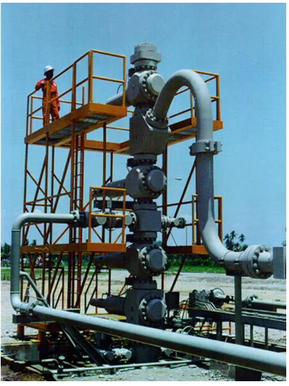
The OFE development project in the refurbishment of critical equipment is a systematic process as suggested on API spec 6A for re-manufacturing annex H [2]. Fig. 2 is the general Christmas tree assembly as critical equipment in the good field.
Fig. 2 Example of Christmas tree OFE
B. The Risk Management Process in Oil Development Project
Generally, a project risk management (PRM) has been developed to associate the process model in the literature [6]:
1) Plan Risk Management: It is defining how to conduct risk management activities for OFE project. The risk management plan is vital to communicate with an agreement and knowledge supported by all stakeholders to ensure a risk management process is performed effectively over the project life cycle.
2). Identify Risk: Make a List of all potential impact on the project [6] .It’s a process of detection which a risk may be affecting and dangerous forwards the project. The objective is for the PM to anticipate event occurred of the risk. Identifying risk is a typical continuous iterative process that causes the risk to exist and identified during project through its life cycle.
3) Qualitative and Quantitative Analysis: In practice, these are the methods in nature to further analysis by assessing the probably and impact of the risk and used a numerical data collection. This process is to obtain risk assessment documentation [6].
4) Risk Prioritization: It can be conducted as long as a measurement of priority system is used and taking from qualitative and quantitative risk list into account with rank.
5) Risk Response: To develop option and action to enhance opportunities and reduce/eliminate a thread to
project objectives. This process is following the qualitative and quantitative risk analysis process. Selected the optimum risk response from each option is required to address the risk.
6) Monitoring Risk: It can be monitored along the process in progress. Implementation of risk response plan, tracking the risk and evaluate with risk response. Evaluating implementation risk assessment effectiveness and review to issue a trigger impulse to support make a decision of significant change for risk assessment.
C. Techniques for Risk Identification by Using Fishbone Diagram (Outline)
A fishbone diagram or cause and effect analysis is a graphical representation of root-cause of the problems. This is a typical analysis of potential failure with use a group and breaks down into detailed sources [7].
This method was developed by Ishikawa [8]. It helps a user (engineer) to think and identify risk trough problem cause. To develop this method, there are major steps as follow to identify a potential problem, i.e. looking to the major factors, identifying the possible causes, and analyzing the cause-effect with a diagram. This is including which used a numerous problem or failure into risk management method [9].
The fishbone diagram helps a design engineer to identify a potential failure as guidance for their calculation from all aspect such material, manpower capability, process machine capability and own engineering role. Risk identification is to study a condition to realize a potential happen in product design inclusive interface in client equipment connection during project run [10].
Risk management is required to identify a potential risk anything and anywhere and anyhow from a product that can be possible a negative or positive impact in beginning process until used in field or client. To search the potential risk or potential failure can seek into two kinds of thing that from source analysis and problem analysis [6].
This fishbone analysis is commonly good in practice way to reveal inside picture of one issue. Even tough the analysis of the quality of the product are mostly performed by an organization; there is an opportunity to implement in engineering design stage activity during releasing the outcome of product design output to prevent any failure happened in next processes until product the is delivered in market or field.
The simple diagram of cause and effect analysis (Fishbone) as shown in Fig. 3.
Fig. 3 Model of fishbone analysis to the risk Possible cause/risk
Possible cause/risk
Possible cause/risk
Possible cause/risk Possible cause/risk
III.RESULT AND DISCUSSION
A. Risk Management Framework in Oil Field Development Project by Enclosing Fishbone Analysis
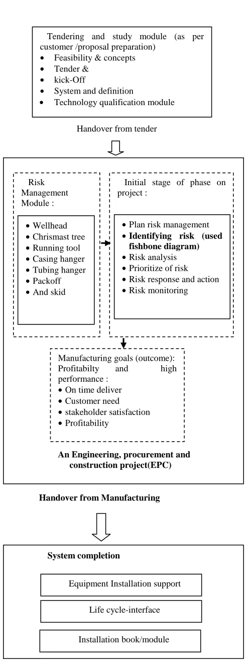
The used method is presented from the process of OFE that is focussing on the method in engineering stage and role which covers the risk management process that has a possibility to attach or enclose a fishbone diagram during their performing design package upon releasing into production floor and logistic. There are several techniques that commonly used in industry. Most electronic companies which are mass production used this technique tool for control the quality of the product. This situation brings this to propose the method in oil field equipment manufacturing to identify risk in engineering aspect to use the framework as shown in Fig. 4.
The risk in engineering area is a major risk. If poor design cause of time delivery, cost and quality achievement and then expertise person is required to focused on a resolution for project constraints on design and engineering. Several spare parts and material are quick difficult to supply with limitation sources and lead time. Supply Chain Management (SCM) become a critical thing because the demanding material and high dependence on supplier or vendor make a manufacturer at a high risk. Substitute material and deviation may be effect to quality and reliability a product or equipment and become a risk. This risk will be taken by an engineering side as they do for design calculation and analysis to releasing approval of the scenario to meet delivery on the project.
Product specification level is the requirement for all product including material selection such as temperature range, material grade and code, as well as manufacturing processes such welding and testing. There are five product specification levels: PSL 1, 2, 3, 3G and 4 in API 6A [2]. These five PSL designations define different levels of technical quality requirements. According to API 6A Annex A, selection of PSL should be based on a quantitative risk analysis, which is a formal and systematic approach to identifying potential hazardous events and estimating the likelihood and consequences to people, environment, and resources, of accidents developing from these events. PSL 1 includes practices currently being implemented by a broad spectrum of industries for recommended service conditions [2].
PSL 2 includes all the requirements of PSL 1 plus additional practices currently being implemented by a broad spectrum of the industry for a specific range of service conditions. PSL 3 includes all the requirements of PSL 2 plus additional practices currently being implemented by a broad spectrum of the industry for a specific range of service conditions [2]. PSL 3G includes all the requirements of PSL 3 plus additional practices currently being implemented by a broad spectrum of the industry for a specific range of service conditions. The designation PSL 3G is utilized only in those clauses, subclauses, and tables where it is necessary to define the additional gas testing requirements of equipment that can be gas-tested.
Fig. 4 Framework study to propose implementation fishbone diagram analysis into risk management in oil field development project
System completion
Installation book/module
Tendering and study module (as per customer /proposal preparation)
• Feasibility & concepts • Tender &
• kick-Off
• System and definition
• Technology qualification module
Handover from Manufacturing Risk
Management Module :
Initial stage of phase on project :
An Engineering, procurement and construction project(EPC) •Wellhead
•Chrismast tree •Running tool •Casing hanger •Tubing hanger •Packoff •And skid
•Plan risk management •Identifying risk (used
fishbone diagram) •Risk analysis •Prioritize of risk •Risk response and action •Risk monitoring
Manufacturing goals (outcome):
Profitabilty and high
performance : •On time deliver •Customer need •stakeholder satisfaction •Profitability
Handover from tender
Handover to customer Equipment Installation support
PSL 4 includes all the requirements of PSL 3G plus certain additional requirements and is intended for applications that exceed the service conditions usually identified within the scope and is normally used only for primary equipment. According to (API 6A) performance requirements are specific and unique to the product in the as-shipped condition. All products shall be designed to perform according to the requirements of service condition (temperature rating, pressure rating, material class rating, designed methods, tolerances/miscellaneous in design, design documentation, design review and design validation) and the relevant requirements specified for standard parts and accessories) while in the pressure and temperature ranges and used with the test fluids consistent with the material class for which they are rated. Other requirements specified by the purchaser may include load capability, cycles, lubrication and operating force or torque [2]. There are two performance requirement levels: PR1 and PR2 as also required [2].
Equipment shall be designed to operate at only the following maximum rated working pressures : 13,8 MPa (2 000 psi), 20,7 MPa (3 000 psi), 34,5 MPa (5 000 psi), 69,0 MPa (10 000 psi), 103,5 MPa (15 000 psi), 138,0 MPa (20 000 psi) [2].
Choosing the temperature rating is ultimately the responsibility of the user or customer. In making these selections, the user should consider the temperature the equipment can experience in drilling and/or production services) [2].
Equipment shall be designed with materials, including metallic’s, that meet the requirements. It does not define either the present or the future wellhead environment but provides material classes for various levels (PSL) of the severity of service conditions and relative corrosively [2].
Corrosion is the disintegration of an engineered material into its constituent atoms due to chemical reactions with its surroundings. In the most common use of the word, this means electrochemical oxidation of metals in reaction with an oxidant such as oxygen. It happens because a colourless and poisonous gas that exist in many oil and gas wells. H2S causes embitterment of the metal, which eventually leads to sulphide stress cracking (SSC). H2S also lowers the pH of the water that it dissolves into3 requirements for SSC to occur such: chemical composition of the material is susceptible to H2S, the tensile stress acting on the body (including residual stress) and part is constantly exposed to H2S.
Documentation of designs shall include methods, assumptions, calculations and design requirements. Design requirements shall include, but not be limited to, those criteria for size, test and operating pressures, material, environmental and other pertinent requirements on which the design is based. Design documentation media shall be clear, legible, reproducible and retrievable. Design documentation shall be retained for five years after the last unit of that model, size and rated working pressure is manufactured. Design documentation shall be reviewed and verified by any qualified individual other than the individual who created the original design. Manufacturers shall document their design validation procedures and the results of design validation of designs. The design validation procedures,
including acceptance criteria. Additional validation procedures, including acceptance criteria, it specified by the manufacturer or purchaser [2].
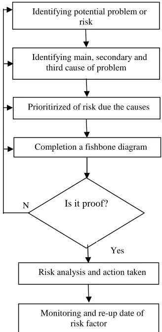
Fig. 5 Logic shame to implementation fishbone diagram analysis into risk management in oil field development project
B. Implementing Fishbone Diagram in Risk Management in Oil Field Development Project
To implement this method, the logic scheme of fishbone diagram in Fig. 5 may be used and followed. A special focusing and attention shall give to problem identifying as risk identification and risk formalization than following the risk analysis, prioritizing, action and monitoring. Fishbone diagram is used for root cause analysis to investigate the underlying causes of specific issues and event that commonly applied to quality objection in manufacturing and industry. The fishbone diagram is a good way to represent an easy method and standardized way to investigate cause and risk prediction base on the root of the processes in the flow of manufacturing and project [7].
In terms of making a Fishbone Analysis, there are several steps that must be done to be prepared : preparing a fish bone analysis session, identify consequences of risk or problems, identify the various categories of the main reasons, finding potential causes by way of brainstorming, reviewing each category of the main causes and reaching agreement on the causes that are most likely the risk happen.
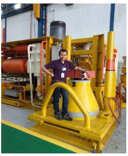
C. Case Example
The working of the proposed approach is provided with support and help of a case example of a field service for
N
Identifying potential problem or risk
Identifying main, secondary and third cause of problem
Prioritirized of risk due the causes
Completion a fishbone diagram
Is it proof?
Monitoring and re-up date of risk factor
equipment installation. In this case example, fishbone analysis for OFE installation service was conducted by Expert Engineer to analysis the effect of failure on the risk during installation equipment to attach to main equipment in the well field. To find out a risk, a survey and observed on the engineering activity was conducted to practitioner team in the industry. The 4 S's as used in the service industry provides a reference four main factors for initiating the construct of fishbone diagram that includes: Surroundings, Suppliers, Systems, Skills. The general of typical fishbone diagram on this example case as Fig. 7.
Fig. 6 Example OFE installation in well field
D. Limitation of Implementing the Fishbone Analysis in Risk Management in Oil Field Development Project
The fishbone method is an effective tool to find out the problem happened and proposed to implementing use to identify and find out the potential problem and risk [10]. As the fishbone is commonly are used in quality function and role, and the limitation is an organization shall emphasize that the method will be helpful in engineering aspect. However, the fishbone pattern had been implemented on several used well in optimizing in SAGD process (steam Assisted Gravity Drainage [11]. Fishbone method has also used in warehouse layouts to find the optimization model of design [12]. Some organization in industrial oil field equipment is a high demand for engineering responsibility on product design, and engineer would be expecting skill to have fishbone knowledge and strongly analysis skill beside of design in the product.
The advantage of Fishbone diagram is able to describe any problems that occur, can identify the risk or potential problem or failure happen. And everyone involved in it can offer suggestions that may be the cause of the problem. However, the disappoint of a fishbone diagram is based on
opinion in the design tool and limitation the ability of the team or user by visually in describing these problems using the method "level why" with deeply, unless the paper used properly, really big to fit those needs. As well as the voting is usually used to select the most likely causes and potential risk are listed on the chart.
To have strong on analysis of risk and potential issues and drawn onto fishbone analysis the engineer would be performed on communication with stakeholder including client, sales, supply chain, manufacturing department, logistic and service completion equipment. By improving effective communication in between an organization in the industry with stakeholder or vice versa would be an advantage to achieve project objectives.
Fig. 7 Example fishbone diagram to identify risk of OFE installation in well field
IV.CONCLUSION
The necessary implementation risk identification by using fishbone analysis on risk management for OFE development project has been discussed with taking literature, industry standard, and experimentally study. It is clear definition that risk can be managed and monitor by enclosing fishbone analysis than following an action on risk management concept. To get strong analysis performing by personal in an organization such engineer and PM, would like to implement two-way communications for stakeholders and PM team. The framework that added a Fishbone analysis method in engineering role may become a standard model and may work as a reference for academic and practitioners to help evaluate which risk management need to emphasize in order to maximize the organization in industry outcome from each stage of the model. The framework model may also use for reference of developing the oil field development project with simple process and can be developed with the same concept for the next wide development project in industry.
ACKNOWLEDGEMENT
We would like to thank Faculty Engineering Technology UTHM and grateful for industry partner in Batam island and Universitas Batam Indonesia to significant support on this research project.
Torque value Interface design
Manual operate book
Hydroulic/pneumatic
sources Material issues
Actuator valve not work Service engineer
REFERENCES
[1] M. Richard, S David in: Green Project Management, chapter 2, CRC Press NW (2011)
[2] T. Edition, C. Api, M. Annex, a S. Part, and O. F. U. S. National, “Specification for Wellhead and Christmas Tree Equipment,” vol. 2009, no. October 2010, 2013.
[3] J. Oehmen, B. Dick, U. Lindemann, and W. Seering, “Risk Management in Product Development - Current Methods,” 9th Int. Des.Conf. - Des.2006, Vols 1 2, no. 36, pp. 1551–1558, 2006. [4] A. Olechowski, J. Oehmen, W. Seering, and M. Ben-daya,
“ScienceDirect The professionalization of risk management : What role can the ISO 31000 risk management principles play ?,” JPMA, vol. 34, no. 8, pp. 1568–1578, 2016
[5] J. Bowers and A. Khorakian, “Integrating risk management in the innovation project,” Eur. J. Innov.Manag., vol. 17, no. 1, pp. 25–40, 2014.
[6] Project Management Institute, Project Management Body of Knowledge A Guide to the Project Management Body of Knowledge. 2000.
[7] M. Hekmatpanah, “The application of cause and effect diagram in the oil industry in Iran : The case of four liter oil canning process of Sepahan Oil Company,” ABJM, vol. 5, no. 26, pp. 10900–10907, 2011
[8] Ishikawa, K (1990); Introduction to Quality Control; ISBN 4-906224-61-X OCLC 61341428
[9] C. Dobrusskin, “On the identification of contradictions using Cause Effect Chain Analysis,” vol. 39, pp. 221–224, 2016
[10] T. O. N. Bose, The, “Application of Fishbone Analysis for Evaluating Supply Chain and Business Process-,”IJMVSC, vol. 3, no. 2, pp. 17–24, 2012
[11] Zhou, F. Zeng, and L. Zhang, “Improving Steam-Assisted Gravity Drainage performance in oil sands with a top water zone using polymer injection and the fishbone well pattern,” Fuel, vol. 184, pp. 449–465, 2016
![Fig. 1 Model of literature review [3]](https://thumb-us.123doks.com/thumbv2/123dok_us/10040659.1990692/2.595.311.552.265.465/fig-model-literature-review.webp)