FPGA CONTROLLER DESIGN AND SIMULATION
OF A PORTABLE DOUGH MIXING MACHINE
Joseph O. Inwelegbu and Thomas A. Nwodoh
Department of Electrical Engineering, Faculty of Engineering, University of Nigeria, Nsukka, Nigeria
Abstract
Biscuit and chocolate cookies are normally produced by industrial based processes and machinery using analog and IC gate-based Controllers. With the advent of Microcontrollers, Application Specific Integrated Circuits, Digital Signal Proces-sors (DSP) and Programmable Logic Devices, complex industrial systems and con-trols can now be integrated into portable embedded household electronic systems. In this paper, the design and simulation of a Dough Mixer Controller (DMC) with Proportional Integral Derivative (PID) closed-loop motor feedback control, is undertaken for a home-based biscuit Cookie machine. DC motor behaviour is modelled and simulated with Matlab/Simulink. Synthesizable VHDL Design and Simulation is carried out with Quartus II Web-Edition 9.0 and ModelSIM EDA software tools, using an Altera Field Programmable Gate Array (FPGA) devel-opment system to verify the PID algorithm applied. Simulation results show that the PID algorithm programmed into the FPGA-based controller, effectively main-tained the Permanent Magnet (PM) DC motor of the mixer at constant torque over an operational 3-speed range. The mixer agitated the 10g dough ingredients fed into the mixing compartment. Subsequently, the mixture resulted in the for-mation of a proteinous and coherent viscoelastic dough structure, consistent with published works on dough mix-texture. The dough can subsequently be baked into biscuit cookies.
Keywords: FPGA, VHDL, PID controller, Pulse Width Modulation, Full H-Bridge DC motor driver
1. Introduction
The DC motor, a power actuator is widely used in industrial applications. The speed of a DC motor can be adjusted with electronic con-trollers to a great extent, so as to provide easy control and high performance [1,2]. By means of various combinations of shunt, series, and
separately-excited field windings, DC motors (DCM) can be designed to display a wide va-riety of volt-ampere or speed-torque control characteristic; hence they have found use in many applications [3,4].
sim-plicity of use characterized earlier controllers. With rapid advances in control technology, more and more research on digital controllers with computer-based systems have been done in recent years [5,6,7]. Usually, when a Micro-processor or Digital Signal Processor (DSP) is used for digital control, the control algo-rithm is executed sequentially. Migrating to programmable logic control, offers high speed, parallel processing, concurrent processing and short development time, resulting in a fast time to market.
FPGAs consist of three major configurable elements, namely: Configurable Logic Blocks (CLBs) that provide the functional elements; Input/Output (I/O) Blocks (IOBs) that pro-vide interface between the package pins and internal signal lines; and Programmable in-terconnect resources that connect I/O of CLBs and IOBs onto the appropriate network. FPGA based digital controllers have become the most favorable choice for prototyping dig-ital systems. The control algorithms are de-veloped in VHDL which is now one of the most popular standard digital logic Hardware Description Languages (HDLs). It is sup-ported by all major Computer Aided Engi-neering (CAE) platforms, making it very ver-satile [8,9,10].
FPGA advantage lies in customizing pre-viously fixed generic hardware in Microcon-troller units (MCUs) or DSP chips. Hence, the optimized application-specific PWM block in the DMC of this paper, can replace the standard PWM block found in a MCU or DSP-based motor-control chip, and reduce the Total Harmonic Distortion (THD) due to the motor, by nearly 50% at a high modulation index [11]. Here, an Altera FPGA controller is designed and programmed to control the speed of the Permanent Magnet (PM) DCM of a portable dough mixing machine, using the Proportional Integral Derivative (PID)
algo-rithm with Pulse Width Modulated (PWM) signals.
2. Relevant Literature
FPGA-based PID control scheme have been widely applied to DCM control applications by many researchers. Abdelati presented the implementation of PID controller for a DCM on an FPGA board. Several modules neces-sary for building PID controllers on FPGAs which improve speed, accuracy, power, com-pactness, and cost effectiveness were outlined in the work [12,18].
Li et al implemented a parallel PID al-gorithm with fuzzy gain conditioner on an FPGA and conducted a simulation-based study [21]. Chen et al implemented a com-plete wheelchair controller on FPGA with par-allel PID algorithm [13]. Correia et al also presented a standard DCM speed control de-sign for a test car [14]. The LED, display and pushbutton modules were automatically gen-erated by an EDA system. The implemented platform permits: (a) to control directly the real vehicle using control commands that are sent using a keyboard and (b) to simulate the control process in a virtual environment, using a virtual instrumentation approach.
Gras et al reported the development of a prototype Micro Z-arm Mixer for measuring flour [17]. The instrument consists of a tem-perature controlled mixing bowl and a speed-controlled DCM. Results obtained with the mixer were highly correlated with those ob-tained with the conventional equipment.
Portable Dough Mixing Machine FPGA Controller 49
D
D
HPI
D
!
" #
Z D
$
%
&IZ
Figure 1: General model of a DCM.
Figure 2: Mathematical model of a DCM.
Kowalski et al presented the position con-trol of an unmanned electrical dual rotor he-licopter. The experimental tests were per-formed with the National Instruments indtrial computer with RIO PXI- 783 1R card us-ing LABVIEW software. The rotor speed was measured by an encoder for comparison with the estimated speed. A prototyping board is the central piece with a PC and motor drive circuit attached [36].
2.1. Mathematical model of a DCM The general model of the DCM is depicted in Figure 1. The applied voltage V(t) con-trols the angular velocity (t). The relations for the armature controlled DC motor are shown schematically in Figure 2.
The dynamical model of the DCM is given by the following equations [15],
Va(t) = La dia(t)
dt +Raia(t) +Vemf(t) (1)
Tm =J
dωm(t)
dt +Bωm(t) +T(t) (2)
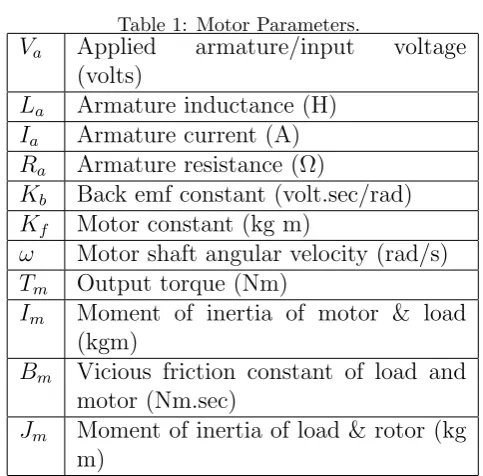
Where the parameters and variables are de-fined in Table 1 following.
Table 1: Motor Parameters.
Va Applied armature/input voltage
(volts)
La Armature inductance (H) Ia Armature current (A) Ra Armature resistance (Ω)
Kb Back emf constant (volt.sec/rad) Kf Motor constant (kg m)
ω Motor shaft angular velocity (rad/s)
Tm Output torque (Nm)
Im Moment of inertia of motor & load
(kgm)
Bm Vicious friction constant of load and
motor (Nm.sec)
Jm Moment of inertia of load & rotor (kg
m)
The output torque Tm of the motor is
pro-portional to the armature currentia, i.e. Tm = Ktia. By omitting the static friction, if one
regards the applied armature voltage Va(t) as
the input and the angular velocityωo(t) of the
motor shaft as the output and also assume
LaIm ≈ 0, the transfer function from (1) and
(2), is given as [15]:
G(s) = Kωo
s+ωo
(3)
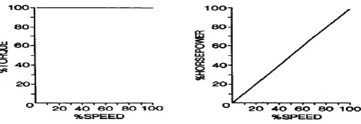
DC Motor at Constant Torque Oper-ation
Many industrial applications such as convey-ors, mixers, squeeze rolls, processing machin-ery, etc., require nearly constant torque over their operating speed range [16]. A PM DCM was chosen for this research, because they ex-hibit an approximate constant torque charac-teristic over their speed range as shown in Fig-ure 3, to deliver a constant torque to the agi-tator over varying speeds for uniform mixing of biscuit dough.
PWM Control
Figure 3: PM DCM Constant torque characteristics.
PWM, a time dependent varying output volt-age is achieved in the process of varying the pulse by controlling the switching of the input voltage for the off and on duration. Figure 4 shows a square wave PWM pulse with 50% duty cycle.
As shown, if the input voltage Vin can be
switched on and off frequently at the uniform rate then the total period T will be:
T =Ton+Tof f (4)
Where: Ton = ON time and Tof f = OFF
time. For a 50% duty cycle, the output volt-age is 0.5 * Vin. In this design, the Vin =
FPGA input voltage = 3V dc. This is boosted by the full H-bridge IC at 24V DC, to drive the mixer DCM. In general, the output volt-age is:
Vavg =
Ton Ton+Tof f
∗Vm
→Vavg = (D)∗Vm (5)
Where: Vavg = average output voltage, and D = duty cycle. The PWM signal from the PWM block of FPGA controls on and off pe-riod of each terminal of the full H-Bridge tran-sistor controlling the motor, and hence the speed.
Speed Control Methods of DC Motors The speed of a motor can be controlled by
open loop and closed loop control strategies. In the PID closed-loop control as applied in this research, the control value is dependent on the output speed of the motor. An open loop control does not. Figure 5, illustrates the losed-loop control of a DCM to maintain the controlled speed at the desired reference speed [18,19,20].
The control objective is to make the motor speed follow the reference input speed change by designing an appropriate controller. The goal is to eliminate the error between P the controlled variable (motor speed) and the de-sired speedPd. The value ofP is measured by
the sensor, an optical speed encoder, which is compared with Pd to generate the error e(t).
The controlled output u(t), is a function of
e(t). In this research, this is the PWM sig-nal, which is fed to the full H-Bridge driver to power the mixer motor.
PID Control Algorithm
In-Portable Dough Mixing Machine FPGA Controller 51
Figure 4: Square wave with 50% duty cycle.
GW G
L
Figure 5: Closed-loop speed control system
tegral terms, giving U(t) the output signal, as found in relevant literatures [21,22]. Con-sider the ideal PID controller written (assum-ing Uo = 0) in the continuous (analog) time
domain form as:
U(t) = Kpe(t)+Ki
Z t
o
e(t)dt+Kd de(t)
dt (6)
Where: Kp = proportional gain;Ti = integral
time; T d = derivative time; e(t) = tracking error. There are several methods to calculate
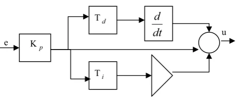
P,I and Dterms. The references [22,23] pro-vides the detail of all tuning methods, with their functional graphs. To design the dig-ital PID controller in an MCU or FPGA de-vice requires the standard PID controller with schematics in Figure 4, to be discretised. Tp, Ti, andTddenote the time constants of theP, I and D terms.
To discretise the controller requires the inte-gral and the derivative terms to approximate to forms suitable for computation by a com-puter. The transfer function of the system in
GW G
G
L
&
S
Figure 6: PID controller schematics.
Figure 6 is given as:
u
e(s) = H(s) =Kp
1 + 1
Tis
+Tds
(7)
The discretized digital controller is given as a difference equation by [24]:
U(n) = Kpe(n) +Ki n
X
j=0 e(j)
+Kd(e(n)−e(n−1)) (8)
Where e = error, K = KpT
Ti is the integral
coeffi-cient. To compute the sum, all past errors,
e(0). . . e(n), have to be stored. From equa-tion (8), the digital controller U(n) is given as:
Kp(en−en−1)+Kien+Kd(en−2en−1+en−2)(9)
This form of the digitized PID equation will be used for implementation of the DMC.
PID Tuning Methods
Tuning is the process of calculating the P, I
and D parameters for optimal gains to get an ideal response from a control system. The Trial and Error, Ziegler-Nichols, Cohen-Coon and Software tools, are Methods cited in sev-eral literatures to accomplish this [25]. Trial and Error Method was applied in this re-search.
Trial and Error Method
In this method, I and Dterms are set to zero first and the proportional gain is increased un-til the output of the loop oscillates. Once the
P andI have been set to get the desired fast control system with minimal steady state er-ror, the derivative term is increased until the loop is acceptably quick to its set point.
The Dough
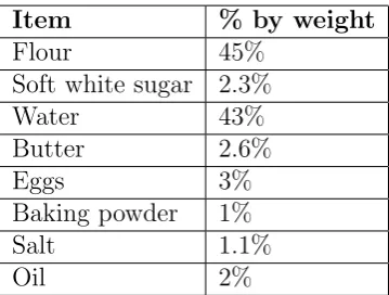
Dough is a paste made out of cereals by mix-ing flour with a small amount of water and/or other liquid. It is precursor to making breads, pancakes, noodles, crusts, pastry, cookies and similar items [26]. Dough is usually a non-Newtonian and viscoeleastic material, exhibit-ing bimgham plastic properties[27]. Cookie dough refers to a blend of cookie ingredients which has been mixed into a malleable form, later to be baked to individual cookies [28]. Biscuit dough may be composed of ingredi-ents listed in Table 2.
Dough can be mixed by an electric mixer [27]. Lindley has proposed a detailed review of mixing operations [29]. Biscuit cookies are made with the mixed dough by setting oven temperature of about 200◦C and baking time
Table 2: Typical Biscuit dough ingredients.
Item % by weight
Flour 45%
Soft white sugar 2.3%
Water 43%
Butter 2.6%
Eggs 3%
Baking powder 1%
Salt 1.1%
Oil 2%
of about 5 minutes, depending on the oven. The mixing time is related to the mixing index
M, by the formula:
lnM =−Ktm (10)
(10) Where K = mixing rate constant, which varies with the type of mixer and the nature of the components, and t(sec.) = mixing time. The smaller the mixing index is, the better the mixing will be. The mixing rate constant
K, depends on the characteristics of both the mixer and the liquids. The effect of the mixer characteristics on K is given by:
K ∝ D 3N D2
TZ
(11)
Where D (metres) = the diameter of the agitator, N(rev/s) = the agitator speed,
Dt(metres) = the vessel diameter and Z(metres) = the height of liquid.
3. Material use for implementation
Portable Dough Mixing Machine FPGA Controller 53
3.0.1. Software:
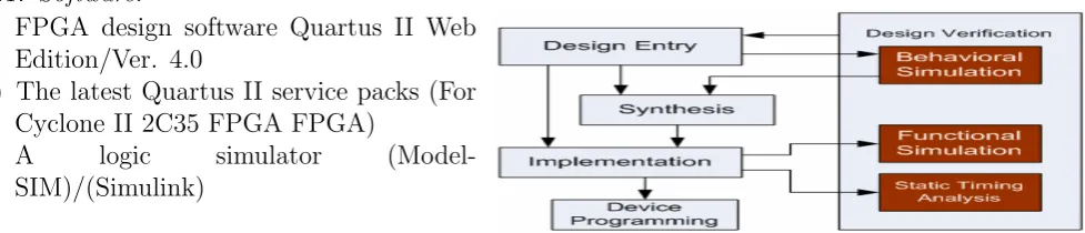
(a.) FPGA design software Quartus II Web Edition/Ver. 4.0
(b.) The latest Quartus II service packs (For Cyclone II 2C35 FPGA FPGA)
(c.) A logic simulator (Model-SIM)/(Simulink)
3.0.2. Hardware:
(a.) DE2 FPGA development board from Al-tera
(b.) A computer system (c.) 24V, DCM
(d.) (d.) L298 (46V, 4A) Full H-bridge motor driver IC
(e.) PC type ATX-300Watts power pack (f.) Optical speed encoder
(g.) Dough mixer container and planetary mixing apparatus
(h.) Tachometer for measuring motor speed in RPM
(i.) Laboratory Microscope, for observing dough microstructure
(j.) Wattmeter, for measuring motor power consumption
(k.) Connectors and cables
3.0.3. Mixer Compartment and Apparatus
Aluminum alloy dough pan with non-stick coating is used. The dimensions of the pan are 5.29 X 5.29 X 5.49 (inches). The tapering and rounded corners of the pan produces an approximate volume of 2230 cm3 [31].
4. Methodology
Figure 7 shows the design steps for any programmable logic device [32].
A detailed explanation of the design methodology steps can be found in relevant literatures [32].
Figure 7: Programmable logic design methodol-ogy.
4.1. Hardware implementation
This section discusses the functional mod-ules of the Dough-Mixer Controller shown in Figure 8.
DE2 FPGA development system
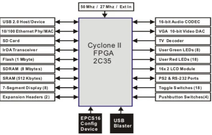
The Altera DE2 board block diagram shown in Figure 9 below features a state-of-the-art CycloneTM II EP2C35 FPGA in a 672-pin package [30]. All important components on the board are connected to pins of this device, allowing the user to control all aspects of the board’s operation.
User Interface
In this research, through the 3-switch/key in-built in the DE2 system shown above, the user inputs an 8-bit value, that specifies the mixer motor LOW/MEDIUM/HIGH speeds of (100/200/300) RPM. This module also han-dles the bounce effect and associated scanning of the switches and the multiplexed 7-segment display units [18].
Optical speed Encoder function
The speed output of the motor is mechanically coupled through an optical encoder. The volt-age encoded speed output (Vf), is fed back to
FPGA through the ADC block. The refer-ence input (Vr) from the speed switch, is then
compared with Vf. The difference (ef)
! "#$%&
"#$%&
'%(
)%%
* +# , -.
'%(
! /
. )%& , 01,203
0/
Figure 8: DMC Architecture and functional modules.
Portable Dough Mixing Machine FPGA Controller 55
PWM and PID algorithm. Speed control is achieved when the sensed speed equals refer-ence speed and error signal (e) given by equa-tion (12) equals zero.
ef =Vr−Vf (12)
In Figure 10(a) and (b), a rotating slotted disk was mounted on motor shaft with a fixed 10 tracks, slotted disk. The frequency of the output waveform fout is given by:
fout =
N rpm
60 (13)
Whererpm= speed in revolutions per minute, and N = number of slots in disc. So, from equation (13), the maximum speed of the PM DCM is given by,
rpm= fout60
N =
50∗60
10 = 300RP M From Figure 10(b), Chip LM324 is used to convert the output square pulses to digi-tal form, readable by ADC block of FPGA. When theVout of photodiode is less thanVref,
the output of LM324 will be 0V (Low) and 5V (High), if vice-versa. The output signal from LM324 has a frequency given by equa-tion (13), and is read by the ADC block of the FPGA, as a representation of the actual switch programmed speed.
PM DC Motor (24V)
The mixer motor and dough container used is same as that used in [31]. Motor and Pul-ley specifications : ECM Motor CA-161200-T, 01R06, 24 V DC, 30 W.
Motor Shaft: 2275 RPM Full speed, 1800 RPM Pulse Speed
Pulley Ratio: (130 teeth on kneading blade shaft / 20 teeth on motor shaft) = 6.5 turn down ratio
Mixer Blade Rotation: 350 RPM, Maximum PWM Speed
Motor maximum Load = 0.58 Amps, 67 Watts.
%,%)-.4%
., 861"9$ 6"3:.
5 .;'% 861<9$ 63:.
Figure 11: DCM drive shaft and Mixer agitator shaft and pulley system.
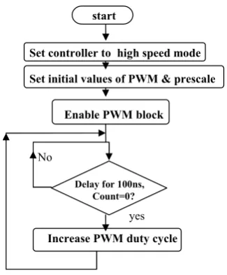
PWM BlockPWM systems control direc-tion, speed, and average torque of a motor. The PWM block of the FPGA interfaces to the motor through the H-bridge driver. It sends speed modulated signals to control duty cycle of full H-bridge DCM driver, through MOSFETs (IRFZ 740). Power is supplied to the motor in square wave of constant voltage but varying pulse-width, determined by equa-tion (4). The speed of a DCM is a funcequa-tion of the input power and drive characteristics. The modulating signal is supplied in 8-bit dig-ital format. With the 50MHz synchronization clock, a minimum pulse width of 100 ns for the synchronization clock period is obtained. A PWM frequency of about 50 Hz is found suitable. To generate this, the modulating sig-nal is multiplied by 212 and a 20-bit counter with 50MHz clock is fired. This counter is compared with the scaled modulating signal. If the scaled modulating signal is larger, the PWM output is set to one, otherwise, it is set to zero, thus the PWM algorithm flowchart shown in Figure 12, is implemented success-fully.
Mixing Apparatus
56 J.O. INWELEGBU and T.A. NWODOH
/
9)
'!
+
Figure 10: (a) Basic configuration (b) Schematic circuit.
%,%)-.4%
'%-.'%(
%&52 )67
<
-.)&&%
#)
%%#$
Figure 12: PWM flowchart.
therefore a small mixer with planetary agita-tor is adequate.
4.2. Software implementation
The controller software embedded within the target CyclonerII 2C35 FPGA running at 50 MHz clock calculates the necessary duty cycle and generates PWM signals for the full H-bridge driver through the PWM block. Us-ing the PID algorithm (shown in Figure 13) implemented in the PID block, the DCM speed is maintained at the required constant value. Figure 14, shows the DMC system con-trol blocks, Figure 15, shows the digital PID
controller equation block. Figure 16 shows the hierarchical diagram of the PID controller Im-plementation. Quartus II Ver. 4.0 and Mod-elSim XE III 6.3c software tools were used for building and testing these modules.
PID Algorithm Description
The PID block is implemented in VHDL lan-guage using dedicated libraries from Altera. The flowchart of the algorithm is shown in Figure 13.
Software Implementation of the PID Algorithm
VHDL software modules used include the key scanning and 7-segment multiplexed display routines, PWM block and the PID block and the system reset. To resolve the digital PID equation (8) of the PID block, VHDL libraries built for algebraic manipulation in VHDL are used. Several works aided this research [33, 34]. A digital PID controller can be repre-sented by the following expression [33]:
u[k] = u[k−1] +e[k](kp+kd+ki)
+e[k−1](ki −kp−2kd)
+e[k−2]kd (14)
This is another form of equation (8). Equation (14) is represented in Figure 15. The register error block stores values of e[k], e[k−1] and
Portable Dough Mixing Machine FPGA Controller 57
Figure 14: DMC system control blocks.
%$))%%))
($%#$ (
($6$%#$4+)&65
: ,,%)
%)%%%)))
%)%&$))'&)# %%))&$
%)%#
&$))$#
%)%)
$=
<
=)
%,'%22
,%)$ %%
Figure 13: Flowchart for PID algorithm.
. Figure 15:( 5>225Digital PID controller equation block
implementation in programmable logic.
(e[k−1] = e[k] and e[k−2] = e[k−1]). The output register block stores u[k] and u[k−1]. The implemented controller can be visualized in the blocks presented in Figure 14. Four main blocks are observed:
• Error Detecting Block: This block is used for the comparison of the signs TRA-JECTORY (user motor speed, through 3-switches) and ENCODER (Feedback speed read from optical encoder). (+ or sign).
>%%>8
>
,>#$
> >
.>%
>?>@
,>#>,5>
Figure 16: Hierarchical Diagram of PID controller Implementation.
• Control Register Block: it implements the control registers, responsible for the programming of parameters in the FPGA.
• Power Interface Block: it converts the bi-nary word supplied by PID controller in a pattern of digital signs to control the PWM block [36].
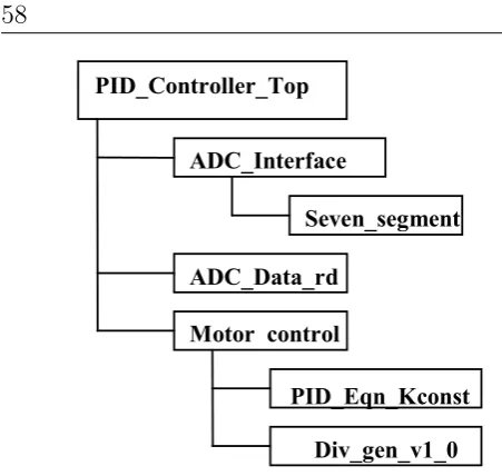
4.2.1. Hierarchical structure of the PID con-troller Software
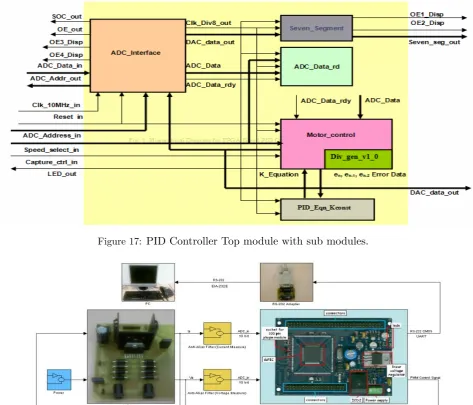
The hierarchical structure of the PID con-troller software implementation is shown in Figure 16. It consists of a top level module called PID controller Top, with functional sub-modules.
PID Controller Top Module
The PID Controller Top module, instantiates the sub modules ADC interface, ADC Data Read and Motor control. It interconnects all the signals and interacts with the external world.
Coregen Divider Module
This is Xilinx/Altera specific module Div gen v1 0, used in the present design.
In-stantiated in Motor Control Module to divide the calculated PID value Vn to get the equiv-alent binary value, which has to be sent to DAC.PID Equation Calculation Module The calculated errors en, en-1 and en-2 with their polarities, is fed to this module from mo-tor control module. This module calculates the PID equation,
Kp(en−en−1)+Kien+Kd(en−2en−1+en−2)(15)
(15) This is a form of the discretized digital controller in equation (8). The constants Kp, Ki and K values are 3, 2 and 1 respectively,
calculated by trial and error method of PID described in section (1.6.1).
5. Simulation of the Controller
Portable Dough Mixing Machine FPGA Controller 59
Figure 17: PID Controller Top module with sub modules.
Figure 18: DMC - FPGA experimental setup. Courtesy: http://dev.emcelettronica.com/print/51811.
Table 3: Synthesis report of the controller (CycloneTM II EP2C35 FPGA logic elements utilization).
Device Spec. of theCycloneTMII EP2C35 FPGA Used by this design
Number of CLBs used 1536 757
Number 4- input LUTs 6144 2648
Number of IOBs 142 39
6. Results and Discussions 6.1. Experimental setup
Figure 18 in the next page, shows the ex-perimental setup. The HP laptop PC running SIMULINK, Quartus II and ModelSIM soft-wares is connected to the DE2 board, through a serial (RS-232) interface. The input inter-faces to the DE2 development system includes the optical speed encoder circuit, the mixer 3-speed toggle switch and the power supply pack, providing +5V DC for logic, +3V DC for the FPGA and +24V DC for the Mixer motor and H-bridge driver. The DE2 out-put interface includes the 3-element seven-segment display and the full H-Bridge mo-tor driver, activated by the controllers PWM block.
Dough Mixing Results
Approximately 10 grams of dough ingredients listed in Table 1 was placed within the mixer chamber. While mixing, torque responses and shaft speeds were collected with tachometer at mixing speeds of 300, 200 and 100 RPM, representing the 3-speed range of the con-troller. For each scenario, torque responses and agitator speeds were collected over a 10-minute interval. Results show that typical dough development times at 100 RPM (LOW-speed) are about 12 minutes, 8 minutes at 200 RPM (MED-speed) and about 5 minutes at 300 RPM (HIGH-speed), averaging optimum dough development time at about 8 minutes. This result agrees fairly well with reviewed lit-eratures, using horizontal and planetary mix-ers [35].
Dough Tensile Properties
The tensile properties of the dough also changed systematically as the dough develops. The maximum tensile force that the dough ex-erts on the agitator as it adheres to the dough surface gets smaller. This is a combination of surface thickness and dough’s cohesive prop-erties. This is supported by results of
fun-damental rheological measurements [35], and also observed from the mixing curve shown in Figure 19.
Mixer power consumption profile The dough mixing curve also shows that the motor power consumption reduced (measure-ments with a wattmeter) after about 6 min-utes, typical of dough when the tensile force exerted on the agitator declined as dough complete development time was approached.
Dough Microscopy
Dough structure was observed under a micro-scope. The microstructure of the dough sam-ples mixed at 100 RPM was quite different from the microstructure of dough mixed at 300 RPM. The 100 RPM set was less devel-oped with coarser protein network, than the dough developed at 300 RPM. Indeed by com-parison, the general effect of higher mixing speed is a finer, more homogenous protein net-work [35].
6.2. Experimental results
Experiment is conducted to verify the con-ventional PID control of the PM DCM of the DMC for speed control. Trial and Er-ror Method was used to tune the PID con-troller. Effective motor speed control was achieved with optimum PID coefficients of P=4, I=0.001 and D=4. In Figure 20, the result of the speed control experiment showed noise behaviour. This is due to the change in sign of error as the motor speed changes to gradually lock at 300 RPM when speed error approaches zero.
Portable Dough Mixing Machine FPGA Controller 61
Figure 19: Dough Mixing curve.
feeds back to the motor through DAC block. The motor started running at set speed as ob-served from a tachometer when the current output speed equals the set speed. For an-other speed, the above procedure is repeated by changing the switch selection. Changing the speed, the ADC voltage also changed. Measured ADC and equivalent Hex values for different set speeds were tabulated in Table 4. It was observed that the current speed, which displays on the onboard 7- segment display, equals the set speed value. The change in the motor speed for different switch combinations can also be observed accordingly.
7. Conclusions
A closed-loop PID algorithm, implemented on FPGA was proposed, designed and simu-lated. The performance is verified and tested. The results demonstrate that FPGAs are well suited for implementation of complex motor control and estimation algorithms due to their parallel and high speed execution character-istics. The VHDL software developed, con-tains a set of building blocks, each geared to-wards a specific algorithm. The test results also showed that with PID algorithm control, the steady-state error is eliminated and the desired output speed is obtained. The FPGA
Table 4: Results of DCM speed control system for various set speeds.
SW. No
Toggle Switch Posi-tion
Set Speed (rpm)
Equiv-alent HEX value
Measured ADC volt-age(V)
1. 000 300 12C 4.5
2. 001 200 C8 2.4
3. 010 100 64 0.64
implementation reduced the total hardware complexity and cost. Simulation results show that when the speed is changed, the motor speed locks to the set speed, when the current error en, previous error en-1 and previous to the previous error en-2 becomes zero.
References
1. Henao H., Capolino G. A., Methodologie et application du diagnostic pour les sys-temes electriques, Article invit dans Revue de l’Electricit et de l’Electronique (REE), No. 6, (in French), Jun. 2002, p. 79 86.
Figure 20: Experimental result of conventional PID control (motor speed scale = X 10 RPM).
3. M.S. Jr. Tomlinson, D.J. Walker, M.A. Sivilott. A digital neural network architec-ture for VLSI. Proc. International Joint
Conference on Neural Networks, pp.
545-550, 1990.
4. Brown, S.D., Francis, R.J., Rose, J., and Vranesic, Z.G. Field-Programmable Gate Arrays. Kluwer Academic Publishers,1996.
5. Dinavahi, V.R.; Reza Iravani, M.; Bonert, R. Real-time digital simulation of power elec-tronic apparatus interfaced with digital con-trollers. , IEEE Trans. Power Delivery, Vol-ume: 16 Issue: 4, Oct. 2001 Page(s): 775-781.
6. A. de Castro, P. Zumel, O. Garcia, T. Riesgo, J. Uceda. Concurrent and simple digital controller of an AC/DC converter with power factor correction based on an FPGA. IEEE Trans. Power Electronics. Vol. 18 pp. 334 343, 2003.
7. Shih-Liang Jung, Meng-Yueh Chang, Jin-Yi Jyang, Li-Chia Yeh, Jin-Ying-Yu Tzou. De-sign and implementation of an FPGA-based control IC for AC-voltage regulation. IEEE Trans. Power Electronics. Vol. 14 pp. 522 532, 1999.
8. http://www.ijetch.org/papers/90New.pdf
9. S. Nerto, S.Bolognani, M. Ceschia, A. Paccagnella, M. Zigliotto. FPGA-based ran-dom PWM with real-time dead time com-pensation. Proc. IEEE PESC03, Vol 2, pp.15-19, (2003).
10. A. Fratta, G.Griffero and S. Nieddu. Com-parative Analysis among DSP and FPGA-based Control Capabilities in PWM Power Converters. The 30th Annual Conference of the IEEE Industrial Electronics Society, Nov. 2004.
11. Monmasson E., Cirstea, M. FPGA Design Methodology for Industrial Control Systems – A review. IEEE Trans. on Industrial Elec-tronics, Vol. 54, No. 4, August 2007.
12. www.iugaza.edu.ps/.../volume%2014-%20Issue%201%20-studies%20-7.pdf
13. R.-X. Chen, L.-G. Chen, and L. Chen. System Design Consideration for Digital Wheelchair Controller. In IEEE Transac-tions on Industrial Electronics, Vol.47, No.4, Aug. 2000, pp. 898-907.
14. http://www.gigiroy.com/index fig-ure/Control 2004 finalised paper 084.pdf
15. DORF, R. C.BISHOP, R. H. Modern
Portable Dough Mixing Machine FPGA Controller 63
1990.
P. Kachroo and P. Mellodge, Mobile Robotic Car Design, McGraw-Hill, New York, 2005.
16. http://www.usmotors.com/Products/dc hsc.pdf
17. GRAS, P. W. VARGA, J. RATH, C. TM-SKZI, S. FODOR, D. SALG, A. BKS, F. Screening for Improved Water Absorption and Mixing Properties Using Four Grams of Flour: A New Small-Scale Farinograph Type Mixer. In: Proceeding of 11th Inter-national Cereal and Bread Congress, Broad-beach, Qld, Australia (2000).
18. Mohamed Abdelati. FPGA-Based PID ControllerImplementation. The Islamic University Of Gaza.
19. Y. F. Chan, M. Moallem, W. Wang. Ef-ficient implementation of PID control algo-rithm using FPGA technology. Proceedings of the 43ed IEEE Conference on Decision
and Control, V5, PP. 4885-4890, Bahamas
2004.
20. J. Tang. PID controller using the TMS320C31 DSK with on-line parameter adjustment for real-time DCmotor speed and position control. IEEE International Symposium on Industrial Electronics, V2, PP 786-791, Pusan 2001.
21. Ang K., Chong G., Li Y. PID control sys-tem analysis, design, and technology. IEEE Trans. Control System Technology, vol. 13, p. 559 576, Jul. 2005.
22. http://www.Wikipedia.org/wiki/PID con-troller
23. Popov A., Farag A., Werner H. Tuning of a PID controller Using a Multi-objective Op-timization Technique Applied to A Neutral-ization Plant. 44th IEEE Conference on De-cision and Control, and the European Con-trol Conference 2005.
24. R. Isermann. Digital Control Systems. Springer-Verlag, 1989.
25. Lee, Y., Lee, J., Park, S. PID Controller Tuning for Integrating and Unstable Pro-cesses with Time Delay. Chem. Eng. Sci.,vol. 55, pp. 3481-3493, 2000.
26. http://www.wikipedia.com/dough.htm
27. http://www.correllconcepts.com/Encyclo-pizza/05 Dough-making/ 05 dough-making.htm# Toc533730361
28. http://www.wikipedia.com/Cookie dough.htm
29. Lindley, J.A. Mixing processes for agricul-tural and food materials: Part 1. Funda-mentals of Mixing, Journal of Agricultural Engineering Research 48: 153 - 170, 1991
30. www.ece.rochester.edu/courses/ECE112/...-/DE2 UserManual.pdf
31. http://www.engr.uky.edu/ aseeched/papers-/2001/a0322.pdf
32. Modelsim Xilinx Edition, Xilinx Inc. 2005.
33. Samet, L. Masmoudi; N. Kharrat, M.W. Kamoun, L. A digital PID Controller for Real Time and Multi Loop Control: a Com-parative Study. IEEE International Confer-ence on Electronics, Circuits and Systems, pp. 291 - 296, vol.1, 1998.
34. Klotchkov, I. V.; Pedersen, S. A Codesign Case Study: Implementing Arithmetic
Func-tions in FPGAC’s. IEEE 1996.
35. http://ses.library.usyd.edu.au/bitstream/21-23/2569/1/QWCRC%20Report%202.PDF