Vol.7 (2017) No. 4
ISSN: 2088-5334
Hammerstein Model Based RLS Algorithm for Modeling the
Intelligent Pneumatic Actuator (IPA) System
Siti Fatimah Sulaiman
1,2, M.F. Rahmat
1#, A.A.M. Faudzi
1,3, Khairuddin Osman
2, N.H. Sunar
1and
Sy Najib Sy Salim
41
Department of Control and Mechatronics Engineering, Universiti Teknologi Malaysia, 81310 UTM Johor Bahru, Johor Darul Takzim, Malaysia
E-mail: [email protected], #[email protected], [email protected] 2
Department of Industrial Electronics, Universiti Teknikal Malaysia Melaka, Hang Tuah Jaya, 76100 Durian Tunggal, Melaka, Malaysia E-mail: [email protected]
3
Centre for Artificial Intelligence and Robotics, Universiti Teknologi Malaysia, 81310 UTM Johor Bahru, Johor Darul Takzim, Malaysia
4
Department of Electrical Engineering Technology, Universiti Teknikal Malaysia Melaka, Hang Tuah Jaya, 76100 Durian Tunggal, Melaka, Malaysia
E-mail: [email protected]
Abstract— An Intelligent Pneumatic Actuator (IPA) system is considered highly nonlinear and subject to nonlinearities which make
the precise position control of this actuator is difficult to achieve. Thus, it is appropriate to model the system using nonlinear approach because the linear model sometimes not sufficient enough to represent the nonlinearity of the system in the real process. This study presents a new modeling of an IPA system using Hammerstein model based Recursive Least Square (RLS) algorithm. The Hammerstein model is one of the blocks structured nonlinear models often used to model a nonlinear system and it consists of a static nonlinear block followed by a linear block of dynamic element. In this study, the static nonlinear block was represented by a deadzone of the pneumatic valve, while the linear block was represented by a dynamic element of IPA system. A RLS has been employed as the main algorithm in order to estimate the parameters of the Hammerstein model. The validity of the proposed model has been verified by conducting a real-time experiment. All of the criteria as outlined in the system identification’s procedures were successfully complied by the proposed Hammerstein model as it managed to provide a stable system, higher best fit, lower loss function and lower final prediction error than a linear model developed before. The performance of the proposed Hammerstein model in controlling the IPA’s positioning system is also considered good. Thus, this new developed Hammerstein model is sufficient enough to represents the IPA system utilized in this study.
Keywords—pneumatic; system identification; hammerstein; RLS; valve deadzone
I. INTRODUCTION
Pneumatic system is one type of actuator that is commonly used in industry other than hydraulic, electrical, thermal, and magnetic. This type of actuator will only operate when sufficient compressed air supplied to it. However, like most real systems, pneumatic actuator system is a system that is not linear. This is due the issues such as valve deadzone, air leakage, friction effect, and etc. that are presented in the system [1],[2]. Thus, the modeling process of pneumatic system becomes complicated because of these
issues. Factors that make the system not linear should be taken into account during the modeling process in order to represent the overall system precisely. Over the past decade, many studies have been done to model the entire pneumatic system. Review of previously studies summarized that there are two approaches commonly used by researchers to model the pneumatic system (either linear or non-linear); a theoretical (first principle) and experimental approach [3]-[11].
alternative and easily deal with the complex system or process [12],[13] are the reasons why the latter approach is selected to be employed.
In system identification, there are a few structure of model that can be utilized to represent the system [14]. Recently, researchers have shown an increased interest of using block-oriented or block-structured nonlinear model in modeling the system. A block-oriented nonlinear model is a model that consist a series of blocks that represent both memoryless nonlinearity and linear dynamic of the system based on input and output measurement of the system [15]. Extensive review revealed that a Hammerstein model is among the block-oriented nonlinear model of choice for modeling any system [16]-[20] and studies in [21]-[23] proved that a Hammerstein model can also be used to model the pneumatic actuator system.
Basically, a Hammerstein model consists of a static nonlinear block and linear dynamic block in cascade. In this study, the static nonlinear block of Hammerstein model will be represented by a deadzone of the pneumatic valve, while the linear block will be represented by a dynamic element of the system. Previously studies on modeling the nonlinear system using Hammerstein model also reported that a recursive and iterative algorithm is often a choice to be used as a parameter estimator for the model [16]-[18],[20]. Iterative algorithm is often used in off-line estimation, while recursive algorithm is often used in on-line estimation [20]. Based on the reviews, this study proposes a Hammerstein model as a new model for a pneumatic system utilized in this study and Recursive Least Square (RLS) algorithm as the parameter estimator for the developed Hammerstein model.
This rest of the paper is organized as follows: The IPA system operations and its components are described in Section 2. The methodology and procedures in modeling the IPA system using system identification approach, and the simulation and experimental results based on the new developed model are discussed in Section 3, and the overall findings are concluded in Section 4.
II. MATERIAL AND METHOD
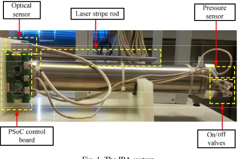
The pneumatic actuator system, namely the Intelligent Pneumatic Actuator (IPA) system utilized in this study is classified as the linear double-acting cylinder type with 0.01mm position accuracy. The system is equipped with five main components (as illustrated in Fig. 1); the pressure sensor, optical sensor, laser stripe rod, on/off valves, and Programmable System on Chip (PSoC) control board. Each of these components has their own function in ensuring the IPA system works well, and each of them is interconnected with each other.
In this study, two valves have been used for controlling the IPA positioning system. Both valves were used to control the inlet and outlet air of the cylinder, and a Pulse Width Modulator (PWM) signal was used to drive these valves. The PWM signal will behave according to the current pressure readings given by the pressure sensor and current position readings given by the optical sensor. While the PSoC control board will act as the “brain” to control the whole operation of IPA system. The system is said to be so-called “intelligent” since it integrates actuator, microprocessor and sensors together in one system [24].
Fig. 1 The IPA system
System identification has been employed as a modeling approach to represent the IPA system utilized in this study. System identification concept can be as simple as a “blind” approach using black-box model concept to obtain a linear and nonlinear model of the system/framework in view of measured exploratory information. Generally, modeling of the system using system identification approach will go through these four accompanying procedures:
A. Experimental Design and Data Collection
For the technique and procedures utilized for designing the experiment, the previous research in [25]-[28] were referred. The components used during the process of collecting data have been listed in Table 1 and the IPA system’s specifications have been described in Table 2.
TABLEI
LIST OF COMPONENTS USED FOR DATA COLLECTION
Component Model Quantity Remarks
Actuator (Double Acting)
KOGANEI-HA: Twinport Cylinders
1
Optical Sensor AEDR-8300 1 Counter Input Pressure Sensor KOGANEI:
PSU-EM-S
1 Analog Input Valves
(On/Off)
KOGANEI:
EB10ES1-PS-6W
2 Analog Output
TABLEII
THE IPA SYSTEM’S SPECIFICATIONS Parameters Value Remarks
Actuator Diameter
40mm
Rod Diameter 16mm Rod Stroke 200mm Maximum Force
(At 0.6MPa)
120N
Ambient Force 0N Specific Heat
Ratio
1.4 ISO 6358
Temperature 294.5K ISO 6358
2000 measurements of input and output data with
experiment. The data contains 2000 data points of signal applied to the valves (input data) and 2000 measurements of the position signal (output data). The signal applied to the valves is a continuous step signal with amplitude ±255, and specially designed for the on/off valves of IPA system. While the output signals represent the position of IPA’s stroke in mm. The plot of input and output data are shown in Fig. 2.
0 2 4 6 8 10 12 14 16 18 20
-255 0 255
Time (second)
C
o
n
tr
o
l
si
g
n
a
l
(a)
0 2 4 6 8 10 12 14 16 18 20
0 20 40 60 80 100 120 140
Time (second)
P
o
si
ti
o
n
(
m
m
)
(b)
Fig. 2 The plot of collected data from real-time experiment: (a) input, (b) output
B. Model Structure Selection
In this study, the Hammerstein model or so-called a block-oriented or block-structured model was used in order to represent the real IPA system. The basic structure of a Hammerstein model consists of a static nonlinear block and linear dynamic block in cascade, as illustrated in Fig. 3. In this study, the static nonlinear block was represented by a nonlinear deadzone of the IPA valve, while the linear block was represented by a linear dynamic of IPA system itself. and represents the input, internal variable, noise and output signals, respectively.
Fig. 3 The basic structure of a Hammerstein model
As previously described, a valve deadzone of IPA system will be considered as a nonlinearity block of the Hammerstein model proposed in this study. A nonlinear valve deadzone in IPA system can be described as a situation where the cylinder stroke does not give any response (extend or retract) for a given range of input voltage to the valve,
until the input voltage reaches a particular value. The analytical expression of the valve deadzone for IPA system utilized in this study was referred from [21],[29] and can be expressed as Equation (1), while its graphical representation can be illustrated as in Fig. 4.
(1)
where and are the deadzone points, and the corresponding segment slopes, and the input and output signals of the nonlinear valve deadzone.
Fig. 4 A graphical representation of the valve deadzone for IPA system
In this study, an auxiliary function called as switching function expressed in Equation (2) and Equation (3) was introduced in order to write the behavior of the deadzone in Equation (1) so that it is linear in parameter [21].
(2)
(3)
Thus, the deadzone equation (Equation (1)) can be represented as Equation (4).
(4)
In this study, the linear block of the Hammerstein model (illustrated in Fig. 3) is represented by a linear dynamic of IPA system and a third order Auto-Regressive with Exogenous input (ARX) has been considered as a model structure in order to describe the system. Thus, the linear part of the Hammerstein model represented in a discrete-time ARX model structure can be written as Equation (5).
(5)
, and
where is the number of system poles, the number of system zeros, the pure delay system, and is the shift operator. So,
Equation (5) can also be written in the form of summations as in Equation (6).
(6)
Substituting Equation (4) into Equation (6) gives Equation (7).
(7)
Then, the complete Hammerstein model for IPA system written in regression equation can be expressed as Equation (8).
(8)
where the regressor vector,
and the parameter vector,
C. Parameter Estimation
In parameter estimation procedure, the mathematical model estimated by a particular estimation technique is measured in term of how accurate the model prediction output compared to the actual or measured output. In this study, the Recursive Least Square (RLS) algorithm will be used to determine the coefficients or parameters of the Hammerstein model. The RLS algorithm has been considered to be utilized in this study since it can provide faster convergence speed/rate and control performance, and it also does not exhibit the eigenvalues spread problem. The RLS algorithm employed in order to estimate the regression equation (Equation (8)) are listed as in Equation (9) to Equation (12).
(9)
where,
(10)
(11)
(12)
where is the least squares weighting factor, the matrix that is proportional to the variance of the previous estimates, the forgetting factor, the current estimation error, the parameter vector, the information vector, and the output vector.
D. Model Validation
In model validation, the validity between the measured and developed Hammerstein model under a validation requirement was checked in order verify that the identified Hammerstein model represents IPA system adequately. In this study, the Akaike’s Model Validity Criterion was employed and the model was validated based on poles location, best fit, loss function and final prediction error. Observing the location of the poles of the system is highly necessary since it provides the information about the system’s stability. The developed Hammerstein model is said to be stable if it manage to keep the location of the poles of the linear model in the range of -1 to 1 (unit circle). Besides, the developed Hammerstein model is also considered acceptable if it manage to provide the model with higher best fit, lower loss function and lower final prediction error. The equation used to determine the percentage of best fit, loss function and final prediction error can be represented as in Equation (13), Equation (14) and Equation (15), respectively.
(13)
where is the measured output, the estimated output and the mean value of the measured output.
(14)
where,
where is the number of data points and the estimation error.
(15)
III.RESULTS AND DISCUSSION
This study presents a new modeling for Intelligent Pneumatic Actuator (IPA) system using nonlinear system identification approach. The aim of this study is to model the entire IPA system using Hammerstein model and estimate all the parameters of the model using a Recursive Least Square (RLS) algorithm. Table 3 shows the estimated parameter values for Hammerstein model obtained using RLS algorithm.
TABLEIII
HAMMERSTEIN MODEL PARAMETER VALUES Block Parameter Estimated
Value
Actual Value
Nonlinear (Valve Deadzone)
1.4120 1.4100 -1.5010 -1.5000
2.3810 2.3800 3.4710 3.4600
Linear (Dynamic of IPA System)
-1.8200 -1.8690
1.0010 0.9976
-0.1808 -0.1284
7.4980×10⁻⁴ 15.6700×10⁻⁴
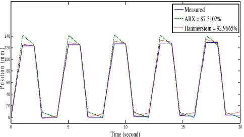
To confirm the acceptance of the developed Hammerstein model, the model has been validated according poles location of a linear ARX model, best fit, loss function and final prediction error. The estimated linear ARX model using RLS algorithm have resulted the entire poles lie inside a unit circle (0.9994, 0.4103±0.1121i), thus proved that the linear ARX model is stable. Meanwhile, the plot in Fig. 5 illustrates the output fittings between the developed Hammerstein model and previous linear ARX model (the model used in previous research) against the measured output (position).
It can be seen that both models produced a good fitting, however, Hammerstein model has managed to give a better fitting than linear ARX model. This indicates that the developed Hammerstein model successfully represents the real IPA system utilized in this study and the addition of nonlinear block (nonlinear valve deadzone) in the model very helpful to get a better model.
0 5 10 15 20
0 20 40 60 80 100 120 140
Time (second)
P
o
si
ti
o
n
(
m
m
)
Measured ARX = 87.3102% Hammerstein = 92.9665%
Fig. 5 The output fittings for a developed Hammerstein model and previous linear model
Apart from the 5.6563% improvement on fitting, the developed Hammerstein model also managed to reduce loss function and final prediction error by 3.5490×10⁻³ and 3.5439×10⁻³, respectively. Summary of the best fit, loss function and final prediction error for both models are tabulated in Table 4.
TABLEIV
MODEL VALIDATION VALUES Criteria
Model
Linear ARX Hammerstein
Best Fit (%) 87.3102 92.9665
Loss Function 4.4000×10⁻³ 0.8510×10⁻³
Final Prediction Error 4.4000×10⁻³ 0.8561×10⁻³
Open-loop and closed-loop test were also conducted in order to test the functional reliability of the estimated Hammerstein model to represent the real IPA system. Fig. 6 show the corresponding responses between simulated Hammerstein model and real-time IPA system for open loop test. As seen in Fig. 6, the simulated Hammerstein model has managed to provide a response that is similar to the real IPA system.
Closed-loop test was also performed on the developed Hammerstein model in order to test its ability to control the IPA positioning system. In this study, a simple Proportional-Integral (PI) (Kp=14 and Ki=1) is used as a controller and the
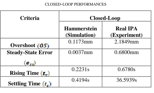
corresponding responses when the set-point to be reached is fixed and unfixed were compared. Fig. 7(a) and Fig. 7(b) illustrate the simulated and actual response of the IPA’s stroke position for fixed and unfixed set-point, respectively. From both plots, it can be stated that Hammerstein model developed in this study can be used to represent the real IPA system, which the response from the simulation was better than the real-time experiment. This is because the simulation does not take into account other nonlinearity factors such as water leakage, friction, air compressibility, etc. as in the real-time experiment. The performance between developed Hammerstein model (simulated) and real IPA system (experiment) for fixed position were compared and summary of the data obtained are tabulated in Table 5.It can be seen from Table 5 that the experiment has provided a higher value for overshoot, steady-state error, rising time, and settling time than simulation. However, the results obtained from the experiment is still acceptable in this study as the overshoot and steady-state error are <10% and <2%, respectively.
0 2 4 6 8 10
0 100 187.54
Time (second)
P
o
si
ti
o
n
(
m
m
)
Experiment Simulation
0 10 20 30 40 50 0
50 100
Time (second)
P
o
si
ti
o
n
(
m
m
)
Reference Simulation Experiment
(a)
0 3 6 9 12 15 18 21 24 27 30 33 36 39 42 45 48 50
0 30 60 90 120
Time (second)
P
o
si
ti
o
n
(
m
m
)
Reference Simulation Experiment
(b)
Fig. 7 Closed-loop test: (a) fixed set-point, (b) unfixed set-point
TABLEV
CLOSED-LOOP PERFORMANCES Criteria Closed-Loop
Hammerstein (Simulation)
Real IPA (Experiment)
Overshoot 0.1173mm 2.1849mm Steady-State Error 0.0037mm 0.6800mm
Rising Time 0.2231s 0.6780s
Settling Time 0.4194s 36.5939s
IV.CONCLUSION
This paper presents a new modeling of Intelligent Pneumatic Actuator (IPA) system using Hammerstein model based a Recursive Least Square (RLS) algorithm. An experimental approach, known as system identification technique was used to develop the model of IPA system used in this study. The nonlinear and linear block for a Hammerstein model was represented by valve deadzone and third-order ARX model for IPA system, respectively. The RLS algorithm was employed to estimate all the parameters for a Hammerstein model. Validation through Akaike’s Model Validity Criterion shows that the developed Hammerstein model is acceptable as it managed to provide a higher fitness, lower loss function and lower final prediction error than the linear model developed before. Thus, shows that the model is good enough to represent the real IPA
system utilized in this study. Besides that, the developed Hammerstein model also proved to be used as a model for the purpose of controlling the position of IPA system. Future study investigating the suitable controller to improve the transient response of the IPA positioning system, especially in real-time environment will be considered as the next stage of this study.
ACKNOWLEDGMENT
The authors would like to acknowledge Universiti Teknologi Malaysia (UTM), Universiti Teknikal Malaysia Melaka (UTeM) and Ministry of Higher Education (MOHE) of Malaysia for their support. The great thanks also go to all of the people who contributed in this study.
REFERENCES
[1] S. N. S. Salim, M. F. Rahmat, A. A. M. Faudzi, N. H. Sunar, Z. H. Ismail, and S. I. Samsudin, “Tracking performance and disturbance rejection of pneumatic actuator system,” in IEEE 2013 9th Asian
Control Conference, 2013, p. 1.
[2] R. Ghazali, Y. M. Sam, M. F. Rahmat, A. W. I. M. Hashim, and Zulatman, “Performance comparison between sliding mode control with PID sliding surface and PID controller for an electro-hydraulic positioning system,”International Journal on Advanced Science Engineering Information Technology, vol. 1, pp. 447-452, Jan. 2011. [3] K. Hamiti, A. Voda-Besancon, and H. Roux-Buisson, “Position
control of a pneumatic actuator under the influence of stiction,” Control Engineering Practice, vol. 4, pp. 1079-1088, 1996. [4] J. Wu, M. Goldfarb, and E. Barth, “On the observability of pressure
in a pneumatic servo actuator,” Journal of Dynamic Systems, Measurement, and Control, vol. 126, pp. 921-924, 2004.
[5] C. R. Burrows and C. R. Webb, “Use of root loci in design of pneumatic servo-motors (pneumatic servomotor synthesis by root loci technique providing direct insight into effects of parameter changes on system response,” Control, vol. 10, pp. 423-427, 1966. [6] I. G. French and C. S. Cox, “Modelling, design and control of a
modern electropneumatic actuator,” in IEE Proceedings D - Control Theory and Applications, 1990, p. 145.
[7] M. Sorli, L. Gastaldi, E. Codina, and S. de las Heras, “Dynamic analysis of pneumatic actuators,” Simulation Practice and Theory, vol. 7, pp. 589-602, 1999.
[8] E. Richer and Y. Hurmuzlu, “A high performance pneumatic force actuator system: part II – nonlinear controller design,” Journal of Dynamic Systems, Measurement, and Control, vol. 122, pp. 416-425, 2000.
[9] A. Messina, N. I. Giannoccaro, and A. Gentile, “Experimenting and modelling the dynamics of pneumatic actuators controlled by the pulse width modulation (PWM) technique,” Mechatronics, vol. 15, pp. 859-881, 2005.
[10] S. Ning and G. M. Bone, “Development of a nonlinear dynamic model for a servo pneumatic positioning system,” in IEEE International Conference in Mechatronics and Automation, 2005, p.43.
[11] G. Carducci, N. I. Giannoccaro, A. Messina, and G. Rollo, “Identification of viscous friction coefficients for a pneumatic system model using optimization methods,” Mathematics and Computers in Simulations, vol. 71, pp. 385-394, 2006.
[12] L. Ljung and T. Glad, Modelling of Dynamic Systems, Prentice-Hall, Inc. Upper Saddle River, NJ, USA, 1994.
[13] D. Hanafi, M. S. Suid, M. N. Ribuan, R. Omar, M. N. M. Than, and M. F. Rahmat, “Speed effect to a quarter car ARX model based on system identification,” International Journal on Advanced Science Engineering Information Technology, vol. 7, pp. 468-474, 2017. [14] L. Ljung, System Identification ToolboxTM User’s Guide, Mathworks,
2015.
[15] X. P. Xu, F. Dai, F. Wang, and F. C. Qian, “An identification method for a block oriented model,” in International Conference on Artificial Intelligence and Industrial Engineering, 2015, p. 425.
[17] W. Lin, H. Zhang, and P. X. Liu, “A new identification method for Hammerstein model based PSO,” in Proceedings of the 2006 IEEE International Conference on Mechatronics and Automation, 2006, p.2184.
[18] K. S. Narendra and P. G. Gallman, “An iterative method or the identification of nonlinear system using a Hammerstein model,” IEEE Transactions on Automatic Control, pp. 546-550, 1966. [19] W. X. Zhao and H. F. Chen, “Recursive identification of
Hammerstein system with ARX subsystem,” in Proceedings of the 25th Chinese Control Conference, 2006, p. 473.
[20] J. Chen, X. Wang and R. Ding, “Gradient based estimation algorithm for Hammerstein systems with saturation and dead-zones nonlinearities,” Applied Mathematical Modelling, vol. 36, 238-243, 2012.
[21] A. C. T. de Cequeira, M. R. B. G. Vale, D. G. V. da Fonseca, F.M.U. de Araújo, and A. L. Maitelli, “Estimation and compensation of dead-zone inherent to the actuators of industrial processes,” in 7th
International Conference on Informatics in Control, Automation and Robotics, 2010, p. 62.
[22] X. Shi and H. T. Zhang, “Modeling of pneumatic muscle actuators based on Hammerstein system,” in Proceedings of the 35th Chinese Control Conference, 2016.
[23] N. H. Sunar, M. F. Rahmat, Z. H. Ismail, A. A. M. Faudzi, and S. N. S. Salim, “Model identification and controller design for an electro-pneumatic actuator system with dead zone compensation,”
International Journal on Smart Sensing and Intelligent System, vol. 7, pp. 798-819, 2014.
[24] A. A. M. Faudzi, K. Suzumori and S. Wakimoto, “Development of pneumatic actuated seating system to aid chair design,” in IEEE/ASME International Conference on Advanced Intelligent Mechatronics, 2010, p. 1035.
[25] S. F. Sulaiman, M. F. Rahmat, A. A. M. Faudzi, and K. Osman, “Design of unconstrained and constrained model predictive control for pneumatic actuator system: set-point tracking,” in 2015 IEEE Conference on Systems, Process and Control, 2015, p.112.
[26] S. F. Sulaiman, M. F. Rahmat, A. A. M. Faudzi, and K. Osman, “Disturbance rejection using model predictive control for pneumatic actuator system,” in 2016 IEEE 12th International Colloquium on
Signal Processing & its Applications, 2016, p. 285.
[27] S. F. Sulaiman, M. F. Rahmat, A. A. M. Faudzi, and K. Osman, “Linear and nonlinear ARX model for intelligent pneumatic actuator systems,” Jurnal Teknologi, vol. 78, pp. 21-28, 2016.
[28] S. F. Sulaiman, M. F. Rahmat, A. A. M. Faudzi, K. Osman, S. N. S. Salim, S. I. Samsudin, and A. R. Azira, “Enhanced position control for pneumatic system by applying constraints in MPC algorithm,” International Journal of Electrical and Computer Engineering, vol. 7, pp. 1633-1632, June 2017.