ISSN 2466-4294 (online) | rad-journal.org Vol. 2 | Issue 3 | pp. 164 – 168, 2017 doi: 10.21175/RadJ.2017.03.034 Original research paper
THE DEVELOPMENT OF THE LIQUID CHROMATOGRAPHY PROCESS
FOR THE SPENT NUCLEAR FUEL REPROCESSING TECHNOLOGY
*L. N. Podrezova
**, V. I. Volk, K. N. Dvoeglazov, S. N. Veselov
JSC A.A. Bochvar VNIINM, Moscow, Russia
Abstract. In spent nuclear fuel (SNF) reprocessing technology, the hydrometallurgical scheme in the version of the classic PUREX process was today accepted. However, in this case mass-transfer operations require significant aqueous flows. The volume of these streams subsequently becomes a liquid radioactive waste (LRW). The reducing of the waste solutions volume in the general SNF recycling process, with the following minimizing of LRW volume, was based on the use of alternative mass-transfer process – liquid chromatography (LC). Uranium-plutonium extract purification by LC process in the simulating SNF reprocessing process was carried out. The dynamic experiments on a laboratory glass column packed with a porous granular high surface material were successfully performed, and the effectiveness of the purification process was evaluated. On the laboratory liquid chromatography column (LCC), a series of dynamic experiments were carried out in order to obtain the original data for the design of a pilot unit. Key words: Extraction, liquid chromatography, mass transfer, reprocessing, spent nuclear fuel, uranium extract
* The paper was presented at the Fifth International Conference on Radiation and Applications in Various Fields of Research
(RAD 2017), Budva, Montenegro, 2017.
1.INTRODUCTION
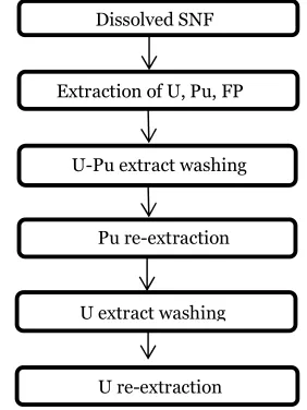
The principal hydrometallurgical schematic of spent nuclear fuel (SNF) reprocessing accepted nowadays consists of the following processes [1,2]:
Figure 1. Schematic diagram of the hydrometallurgical SNF reprocessing
In conventional extraction processes all mass-transfer interactions are carried out in the same way
regardless of the extractor type (mixer-settler, extraction column, centrifugal extractor). Thus there is a dispersion of one phase (discontinuous phase) into another phase (continuous phase), followed by creaming and coalescence of the discontinuous phase droplets into its own continuous phase [3].
However, at the stages of U-Pu extract washing and final uranium extract purification where it is necessary to remove the trace amounts of the impurities, significant amounts of water streams are required. The volume of these streams subsequently becomes a liquid radioactive waste [4].
Therefore, the reducing of the waste solutions volume is an obvious decision that corresponds to the minimization of the liquid radioactive waste volume in the general SNF recycling process. The decision is based on the use of alternative mass-transfer process - liquid chromatography. During the LC process, a significantly less amount of the aqueous solution is used at a flow ratio of extractant/aqueous solution from 40 to 100, and as a result, it causes much less LRW formation (from 8 to 20 times).
2.THE SCHEME OF THE LIQUID CHROMATOGRAPHY
PROCESS
The process was based on mass-transfer operations between the aqueous (stationary) phase and organic (mobile) phase. Pore space of the inert packing of the column (for example grains of silica gel) was U re-extraction
U-Pu extract washing Extraction of U, Pu, FP
165
impregnated by the stationary phase and mobile phase was flowing through the intergrain space. As it passed through the column organic phase was purified from the impurities.
For the SNF reprocessing technology, the LC process was revised and worked out as follows: the stationary phase was an aqueous solution, the composition of which was determined by a specific task, the solution was impregnated to porous grains of a column packing, the mobile phase was flowing in an intergranular space and a large interface area provided an efficient mass-transfer (back extraction) (Figure 2).
Figure 2. Diagram of extract purification process by the method of liquid chromatography
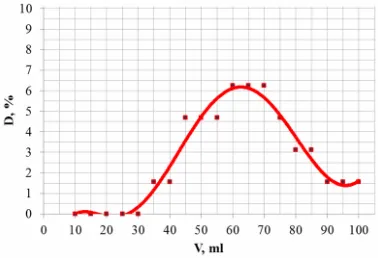
One of the most important indicators of the process efficiency of the liquid chromatography column was the output curve of the impurities concentration with respect to the volume of regenerate.
To determine this parameter, LC columns overloading experiments were carried out using a tracer. Overloading completeness was evaluated by the color intensity of the exiting aqueous solution by the photo colorimeter. As a reference solution, the uncolored 1 mol/l of nitric acid was used.
The results of experiments on the colored aqueous solution substitution through the lower column separation chamber are shown in Figure 3.
Figure 3. Tracer output curve in coordinates D = f (V), showing the column regeneration process
As it could be seen from the figure, the output curve has almost the symmetrical peak corresponding to the volume of 55 ml, which is equal to the column effective volume (52 ml).
3.METHODS AND EQUIPMENT
The valence state of Pu in the course of experiments was monitored spectrophotometrically. Absorption spectra of the solutions were recorded in the wavelength range from 400 to 700 nm on a Perklin Elmer Lambda 35 UV/VIS spectrophotometer. The concentration of the Tc, U and Pu in aqueous solutions was determined on an ICP mass spectrometer.
The concentration of the Tc in solutions was also determined from the specific activity of an aliquot of the Tc in the UltimaGold scintillator on a SCS-50M spectrometer.
As a stationary aqueous phase, nitric acid solutions of organic hydrazine derivatives (Diformylhydrazine and Carbohydrazide) were used. The derivatives were obtained by the interaction of hydrazine with formic acid or with 1 mol/l of nitric acid. 30% of TBP in the isopar-M was used as the organic phase.
The acidity of the solutions and the concentration of the reducing agents were analyzed using a Mettler Toledo DL50 auto-titrator.
A liquid chromatography column was developed and created for the bench testing of the LC process. The scheme of the LC column design is shown in Figure 4 [5].
1 - vertical column with a packed section; 2, 3 - the upper and the lower phase separation chamber; 4, 5, 6, 7 - inputs
and outputs of the phases; 8, 9 – two-point alarms of the interface; 10, 11- overflow windows, 12 - nozzle with a full-way
valve.
Figure 4. Liquid chromatography column design
4.TESTING THE LC PROCESS UNDER LABORATORY
CONDITIONS
Over the past few years, the LC process was developed and it passed a series of tests.
166
4.1. Purification of U-Pu extracts from the fissionproducts
The LC process can be used to purify the U-Pu extract from the fission products, using nitric acid as the stationary impregnated phase. It can be a more effective alternative to the process of the U-Pu extract washing in the apparatus with operation principle of emulsification - delamination.
The experiments of the U-Pu extract purification were performed by the authors [5] on real SNF of VVER-1000 with burn up of 42.5 GW∙d/t of uranium after 15 years of cooling.
The extract composition that was obtained after the dissolution and extraction was as follows: U-95 g/l, Pu – 1.1 g/l, HNO3- 6 g/l.
The extract purification process was performed in a glass laboratory column. The solution of 1 mol/l of HNO3 was an impregnated stationary phase. During
the experiment, 90 column volumes of U-Pu extract were passed through the column. The purification efficiency was evaluated by the activity of the extract output portions.
Uranium extract decontamination factors were as follows: from Eu – 2500, from Cs – 3×10⁵, from
Np – 20, from Am –12.
The value of the purification factors proved the high efficiency of the LC in the U-Pu extract washing operation at a favorable flow ratio: organic phase/water phase ≈ 90.
4.2. U-extract purification from technetium Another possible application of the LC process is uranium extract purification from microquantities of the Tc, which content in the uranium product is regulated by the ASTM C 787-90 standard. The conventional process of uranium extract washing from the Tc generates a large amount of LRW using for these purposes the apparatus with the operation principle of emulsification - delamination. To test the feasibility of an effective change to the LC process, the following experiment was carried out.
The prepared extract was of the following composition: 30% TBP in a dodecane, [HNO3] = 0.12 mol/l, [Tc] = 6.2 mg/l.
As a stationary phase was used the solution of 1 mol/l of diformylhydrazine with 0.1 mol/l of nitric acid. An organic solution containing technetium passed through a column by the upflow mode. The specific load on the packing cross section was 2 m3/(m2·h).
After a certain period of time, the organic phase was taken for the Tc analysis, and the detection limit was 0.01 mg/l. The process of uranium extract purification from technetium proceeded efficiently. The technetium slip in the exit organic solution occurred under the extractant/aqueous solution ratio from 40 to 100.
4.3. U-extract purification from Pu and Tc To assess the possibility of uranium extract purification from the Tc and residual Pu, following experiment was performed.
As a stationary phase, an aqueous solution which comprises a balanced mixture of reductants was used,
one of which (carbohydrazide) had the best kinetic parameters for Pu(IV)→Pu(III) reduction, the other (diformylhydrazine) – for Tc (VII)→Tc (IV) reduction[6,7,8].
The initial extract composition was: [U] =96 g/l, [Tc] = 2.4 mg/l, [Pu] =1 mg/l, [HNO3] = 0.08 mol/l.
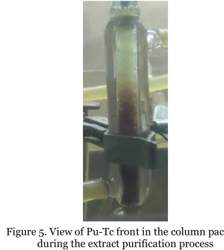
In total, 3 cycles of uranium extract purification from plutonium and technetium traces were performed during the experiment and, accordingly, this led to 3 stages of unloading and regenerating of the packing layer (Figure 5).
The duration of the extraction stage before the extract/aqueous solution ratio of 53 regularly provides the residual content of plutonium and technetium in the purified extract below the detection limit.
The Tc detection limit of the used analysis method was less than 1.0 mg/l, the Pu detection limit was less than 10 mg/l. The extract decontamination factors in each cycle corresponded to the values of not less than 2.4·103 and 102, respectively.
During each cycle, there was a steady progress of technetium and plutonium front at the silica gel packing, wherein an intermediate gas emission was noted.
Figure 5. View of Pu-Tc front in the column packing during the extract purification process
In the course of the experiment, the efficiency of extract purifying from the Pu and Tc was proved at a favorable ratio of organic and aqueous fluxes.
5.BENCH-TESTS OF LC PROCESS IN MIXED URANIUM
-PLUTONIUM NITRIDE FUEL REPROCESSING TECHNOLOGY
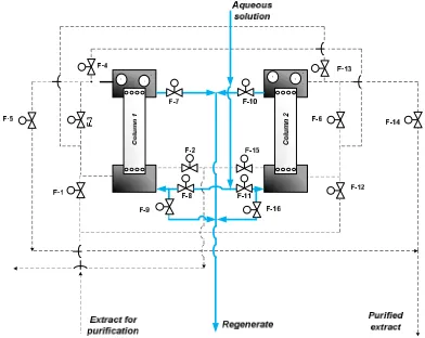
To provide the connection of the continuous organic flow movement during the extraction process and cyclically-periodic LC columns operation mode, two columns were combined into the liquid chromatography unit (Figure 6).
167
disconnected for the regeneration. The second column of the unit ran in the main purification mode. After the regeneration was complete, the column 1 came into operation in a stand-by mode. All solutions were feed into the unit columns in an upflow mode.
Figure 6. Scheme of the flow lines of the liquid chromatography unit and the control and management
system binding
In the technological scheme of mixed uranium-plutonium nitride spent fuel reprocessing, LC units correspond to the following objectives: unit 1 provides
a concentrating
U-Pu extract purification from the fission products at the stage of hydrometallurgical reprocessing; unit-2 provides uranium extract purification from concomitant technetium and plutonium as well as a total decontamination factor of 108. The estimated
effective volume of each column of the refining bench is 1010 ml.
Running of the extraction technology on uranium solutions
Table 1 shows the composition data of initial solutions. The feed solution simulated SNF nitrate solution that was directed to the extraction stage after the dissolution. The extractant composition was (31.8 ± 2.0) vol. percent of TBP in a hydrocarbon diluent C-13. After 29 working hours of LC unit, about 12 liters of the extract were passed through it. Decontamination factors were determined by the difference in input/output organic flow components concentrations of LC unit.
Table 1. Composition of uranium nitrate solutions – feed solution simulators
Component name Feed flow, g/l
[U] 314.8
[HNO3] 284.8
[La] 1.68
[Ce] 0.89
[Ba] 1.11
[Mo] 0.79
[Nd] 2.66
[Zr] 2.03
From the graph in Figure 7 it is seen that LC unit provided uranium purification from impurities – simulators fission products, and decontamination factor for the individual elements was in the range of 3.0 – 18.0.
However, at the 29th hour of the extract purification process, the resource of an aqueous solution was almost exhausted and column regeneration was required.
Figure 7. Extract decontamination factors from simulators of fission products during the first test
The LCC regeneration process was accompanied by a significant decrease in the U and HNO3 content
(Figure 8) in the regenerating solution.
Figure 8. Changes in [U] and [HNO3] in the column
regenerate of unit-1, after 29 hours of operation
This indicates the effectiveness of the column regeneration by the volume of an aqueous solution less than the effective column volume.
Figure 9. Extract decontamination factors at unit-1 from fission products simulators during the second test
168
product simulators in time by the analysis of the inputextract to unit-1 and the output extract during the second test on uranium solutions.
From the given graphs, it is seen that the best decontamination factors were achieved at the 13th hour of the process. Further purification was performed, but with the less efficiency.
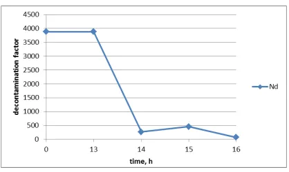
Especially high decontamination factors were obtained for Nd (Figure 10).
Figure 10. Extract decontamination factors at unit-1 from Nd during the second test
Based on the data obtained during the second tests, the extract feed change could be recommended from the first column to the second one after 14 hours of the operating time in a set mode to carry out the overloading of the first column work-off aqueous phase.
The next step was an equipment cascade test on uranium-plutonium solutions, liquid chromatography units operated stably, the control equipment carried out a changeover of the feeding flows in accordance with the scheduled operation modes.
During the tests, the ratio of extractant/aqueous solution was maintained at the values close to 15.
6.CONCLUSION
On the basis of the investigations and tests of the LC process, as applied to the SNF reprocessing technology, the efficacy of the process for extract purifying in general was demonstrated.
The opportunity of the impurities concentration in a small volume of regenerating solution was demonstrated, i.e. a significant increase in the values of the extractant/aqueous solution ratio regarding the ratio for conventional SNF handling technology was obtained.
The engineering equipment of the liquid chromatography units showed a stable operation and provided uninterrupted extract purification during the long-term tests at the pilot testing facility of SNF reprocessing.
Acknowledgement: The authors express their gratitude to main laboratory staff of JSC “Siberian Chemical Combine” for the assistance provided in tests of liquid chromatography process at the pilot testing facility.
REFERENCES
1. А. И. Холькин, В. В. Белова “О классификации экстракционных процессов А. М. Розена,” Химическая технология, т. 17, но. 4, стр. 146 – 154, 2016. (A. I. Kholkin, V. V. Belova, “On the classification of the extraction processes,” Chemical Technology, vol. 17, no. 4, pp. 146 – 154, 2016.)
2. Н. Н. Пономарев-Степной “Двухкомпонентная ядерная энергетическая система с замкнутым ядерным топливным циклом на основе БН и ВВЭР,” Атомная энергия, т. 120, но. 4, стр. 183 – 190, 2016. (N. N. Ponomarev-Stepnoy, “Two-component nuclear power system with a closed nuclear fuel cycle based on FR and VVER,” Atomic energy, vol. 120, no. 4, pp. 183 – 190, 2016.)
3. У. Д. Джемрек, Процессы и аппараты химико-металлургической технологии редких металлов, Москва, Россия: Атомиздат, 1965. (U. D. Jemrek Processes and apparatuses of chemical and metallurgical technology of rare metals, Moscow, Russia: Atomizdat, 1965.)
4. А. А. Копырин, Технология производства и радиохимической переработки ядерного топлива, Москва, Россия: Атомэнергоиздат, 2006. (A. A. Kopyrin, Production and radiochemical reprocessing technology of nuclear fuel, Moscow, Russia: Atomenergoizdat, 2006.)
5. В. И. Волк и др, “Способ проведения массообмена в системе двух несмешивающихся жидкостей и устройство для его осуществления,” RU 2 454 270 C1, июнь, 2012. (V. I. Volk et al., “The mass transfer method in the system of two immiscible liquids and device for the implementing,” Patent RU 2 454 270 C1, Jun. 2012.)
Retrieved from:
http://www1.fips.ru/Archive/PAT/2012FULL/2012.06. 27/DOC/RUNWC1/000/000/002/454/270/DOCUME NT.PDF
Retrieved on: Jan. 28, 2017
6. V. N. Alekseenko et al., “Reduction of Pu(IV) by carbohydrazide in aqueous solutions and in two-phase systems with tributyl phosphate,” J. Radioanal. Nucl. Chem., vol. 304, no. 1. pp. 201 – 206, Apr. 2015. DOI: 10.1007/s10967-014-3882-7
7. V. Volk, E. Pavlyukevich, K. Dvoyeglazov, L. Podrezova, S. Veselov, “Investigation of diformylhydrazine interaction with Pu in technological media of extraction SNF reprocessing,” in Proc. Actinides - 2013, Karlsruhe, Germany, 2013, pp. 1-72.