[Babu* 4(5): May, 2017] ISSN 2349-4506
Impact Factor: 2.785
G
lobal
J
ournal of
E
ngineering
S
cience and
R
esearch
M
anagement
ANALYSIS AND IMPLEMENTATION OF D-SSVR FOR LOAD FLOW SOLUTION
IN RADIAL DISTRIBUTION SYSTEMS
Ch.Lenin Babu*, G.Hanumantha Reddy, P.Vinod Kumar
*
Assistant Professor, Department of EEE, S V Engineering College For Women, Tirupati, Andhra
Pradesh-517507
DOI: 10.5281/zenodo.801285
KEYWORDS
:
Radial distribution system, Load flows, D-SSVR, Voltage improvement.ABSTRACT
In this paper, optimal location of Static Series Voltage Regulator (SSVR),a member of D-FACTS devices family, for voltage improvement and loss reduction in distribution system, is implemented. A simple and modified method for node and line identification used in load flow calculations for solving radial distribution network is presented. In order to minimize line losses of power systems, it is crucially important to define the location of SSVR to be placed in the given distribution system. D-SSVR is a distribution static Series voltage regulator, which corrects the voltage magnitude at the load end irrespective of voltage disturbances at the source. The proposed method is successfully applied to the IEEE-15 bus and IEEE-29 bus distribution systems.
INTRODUCTION
The modern power distribution network is constantly being faced with an ever-growing load demand. Distribution networks experience distinct change from a low to high load level every day. Electric load growth and higher regional power transfers in a largely interconnected network becoming more complex and less secure power system operation. Power generation and transmission facilities are unable to meet these new demands. Electrical power losses in distribution systems correspond to about 70% of total losses in electric power systems. These electrical losses can be considerably reduced through the installation and control of reactive support equipments, such as capacitor banks, reducing reactive currents in distribution feeders and so on. One of the most severe problems faced by distribution networks operators is voltage drop along distribution feeders, which is caused by real and reactive power flow. Voltage control is a difficult task because voltages are strongly influenced by random load fluctuations. Voltage profile can be improved and power losses can be considerably reduced by installing Power Devices or Controllers at suitable location. These controllers which are also named Distribution Flexible AC Transmission System (D-FACTS) and are a new generation of power electronics-based equipment aimed at enhancing the reliability and quality of power flows in low-voltage distribution networks. Among the various power devices, Distributed Static Series Voltage Regulator (D-SSVR) is considered in this paper which is a modified form of DVR and the method for modeling D-SSVR is considered in modified load flow computations. Further the optimal location is identified to place D-SSVR for the purpose of loss reduction and voltage improvement.
[Babu* 4(5): May, 2017] ISSN 2349-4506
Impact Factor: 2.785
G
lobal
J
ournal of
E
ngineering
S
cience and
R
esearch
M
anagement
Series FACTS controllers Shunt FACTS controllers
Combined series – series FACTS controllers Combined series – shunt FACTS controllers
Distribution FACTS Controllers:
Distribution Power Devices is classified into three categories by their structures such as Dynamic Voltage Restorer (DVR), Distributed SSVR (D-SSVR) and Solid-State Breaker (SSB). Among these devices, D-SSVR and the DVR share a similar architecture and both are based on the voltage source converter. DVR and DSSVR are connected in series with the line.
Proposed Distributed SSVR:
Distribution Static series voltage regulator (D-SSVR), is utilized to compensate power quality problems and also it can quickly regulate its susceptance to provide dynamic reactive compensation and regulate the bus voltages in the power system. The D-SSVR is a series-connected, solid-state switching power converter that provides flexible voltage control at the point of connection to the utility distribution feeder for power quality (PQ) improvements such as unbalanced load, voltage sag, voltage fluctuation and voltage unbalance and also exchanges both active and reactive power (voltage) with the distribution system by varying the amplitude and phase angle of the converter. A voltage-source converter is a power electronic device, which can generate sinusoidal voltage with any required magnitude, frequency and phase angle. The VSC is used to either completely replace the voltage or to inject the ‘missing voltage’. The ‘missing voltage’ is the difference between the nominal voltage and the actual. The converter is normally based on some kind of energy storage, which will supply the converter with a DC voltage. D-SSVR belongs to the series voltage controller.
Structure of D-SSVR:
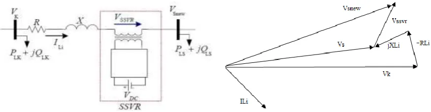
D-SSVR, which is schematically shown in below figure consists of energy storage device, voltage source converter, a coupling transformer connected in series to the distribution network through a coupling transformer.
Figure-1: A typical model of SSVR and Phasor diagram of reactive power exchange
In this model, D-SSVR is capable of injecting active power in addition to reactive power. Since this device is utilized in steady-state condition for long term, because of limited capacity of energy storage system, it cannot inject active power to the system for long term for voltage regulation purpose. Therefore, for the steady-state application, D-SSVR consists of a small DC capacitor and a voltage source converter and the steady-state power exchange between D-SSVR and the ac system is reactive power. The VSC connected in series with the ac system provides a multifunctional topology which can be used for up to three quite distinct purposes:
Voltage regulation and compensation of reactive power Correction of power factor
[Babu* 4(5): May, 2017] ISSN 2349-4506
Impact Factor: 2.785
G
lobal
J
ournal of
E
ngineering
S
cience and
R
esearch
M
anagement
Operation of D-SSVR:
D-SSVR is to suppress voltage variation and control reactive power in phase with system voltage. It can compensate for inductive and capacitive currents linearly and continuously. The VSC converts the dc voltage across the storage device into a set of three-phase ac output voltages. These voltages are in phase and coupled with the ac system through the reactance of the coupling transformer. Suitable adjustment of the phase and magnitude of the D-SSVR output voltages allows effective control of active and reactive power exchanges between the D-SSVR and the ac system. Such configuration allows the device to absorb or generate controllable active and reactive power. The real power exchanges between the inverter and the AC system can be controlled by altering the phase angles between the inverter output and the AC system voltages. The inverter supplies real power to the AC system if the inverter output voltage is made to lead the corresponding AC system voltage. Conversely, the inverter absorbs real power from the AC system, if the inverter output voltage is made to lag the AC system voltage. There are two techniques for controlling the SSVR. The first technique, referred to as phase control, is to control the phase shift to control the SSVR output voltage magnitude. The other technique referred to as Pulse Width Modulation (PWM), allow for independent control of output voltage magnitude and phase shift (phase angle of the output voltage); in this case, the DC voltage is controlled separately from the AC output voltage.
Radial Distribution System Load Flow Method:
Load flow is a very important and fundamental tool for the analysis of any power system and is used in operational as well as planning stages. Load flow analysis of distribution system has not received much attention unlike load flow analysis of transmission systems. However some work has been carried out on the load flow analysis of distribution network. Generally, distribution networks are radial and the R/X ratio is very high compared to a transmission system. This makes the distribution system ill-conditioned. That is why the conventional load flow method such as Newton-Raphson, (NR) and the Fast Decoupled Load Flow (FDLF) method and their modification are not suitable for solving the load flow problem of such an ill-conditioned system. For most of the cases NR and FDLF methods failed to converge in solving the load flow problem of distribution system or converged in high iterations. Distribution Power Flow is an important tool for the analysis of distribution system and it is used in the operational as well as in planning stages. The distribution load flow method is used to calculate the voltage at each bus and total real and reactive power losses.
Consider a single line diagram of two buses of a radial distribution system as shown in Figure-2. Let the number of branches be “nb”, the number of buses “t” and are related through, t = nb+1..
Figure 2: Single line diagram of two buses of a distribution system
Where “R” and “X” are resistance and reactance of the branch. “PLk”and “QLk”are the active and reactive powers of node k. “ILi” is the current flowing in the line. Subscript ‘L’ in “PLS” and “QLS” refers to the load connected at Sth bus. Initially, a flat voltage (1 p.u) at all the nodes is assumed and load currents and charging currents of all the loads are computed using eqns. (1) and (2).
The load current of node k is given by
( )
( )
( )
* ( )
Lk Lk
Lk
P
k
jQ
k
I
k
V
k
for k = 2,3,……nb (1)
The charging current at node k is given by
0
( )
( ) * ( )
Ck
I
k
y k
V k
for k = 2,3,……nb (2)[Babu* 4(5): May, 2017] ISSN 2349-4506
Impact Factor: 2.785
G
lobal
J
ournal of
E
ngineering
S
cience and
R
esearch
M
anagement
i.e.,1 1
( ) ( ) ( )
nb nb
Lk Ck
k n i n
I n I k I k
(3)Where branch impedance is given by Z = R + j X. Therefore, if it is possible to identify the nodes beyond all the branches, it is possible to compute all the branch currents.
A generalized equation of receiving-end voltage, sending-end voltage, branch current and branch impedance is given by V (a2)= V (a1) - I (i) * Z (i) (4)
Where “i”is the branch number
a1 = RE(i) and a2 = SE (i) and RE (i) is the receiving end, SE (i) is the sending end of branch i. The real and reactive power loss of branch “i” are given
Lreal (i) = |I (i) |2 * R (i) and
Lreactive (i) = |I (i) |2 * X (i) (5)
The load flow method of radial distribution network can be solved in three sets of operations: Identification of the nodes beyond all the branches.
Determination of branch currents. Determination of the nodal voltages.
Identification of the nodes beyond all the branches:
By using below algorithm we can find the identification of nodes beyond all branches Step 1 : read the system data.
Step 2 : i =1
Step 3 : k = i + 1, set ip = 0
Step 4 : nc = 0; If {RE (i) = SE (k)} and {ip = 0} go to step 10; Otherwise go to step 12 Step 5 : if {ip = 0} go to step 10;
Otherwise go to step 6 Step 6 : it = 1
Step 7 : if {RE (i) = ie (i, ip+1)} then nc = 1 Otherwise go to step 8;
Step 8 : it = it +1
If {it ≤ ip} go to step 7; Otherwise go to step 9 Step 9 : if {nc = 1} go to step 12;
Otherwise go to step 11 Step 10 : ie (i, ip + 1) = RE (i)
Step 11 : ip = ip +1; IN (ip) =1;
ie(i, ip + 1) = RE(i) N(i) = ip + 1
Step 12 : s = s + 1; if {s ≤ nb} go to step 6; Otherwise go to step 13
Step 13 : if {iP =0}; go to step 14; Otherwise go to step 15 Step 14 : ie(i, ip + 1) = RE(i);
N(i) = ip + 1; go to step 15 Step 15 : i = i + 1; If {i ≤ nb-1}go to step 3;
Otherwise go to step 16
[Babu* 4(5): May, 2017] ISSN 2349-4506
Impact Factor: 2.785
G
lobal
J
ournal of
E
ngineering
S
cience and
R
esearch
M
anagement
Determination of branch currents:
The load current and charging current of each node are calculated by using equations (1) and (2) and identification of nodes are determined. Then it is easy to calculate the branch current is given by
1 1
( ) { ( , )} { ( , )}
nb nb
k k
I i IL ie i k IC ie i k
(6)
Determination of the nodal voltages:
To determine the voltage at each node in radial distribution network, the modified load flow method is used and the algorithm is as follows.
Step 1 : Read the line and load data.
Step 2 : Determine the nodes beyond each branch and their total number.
Step 3 : Initialize the voltage of all nodes to 1p.u and phase angle to zero.
Step 4 : Find all load currents and charging currents of each nodes using Equations (1) and (2) by using these, branch currents are determined given in Equation (3).
Step 5 : Calculate the voltages and phase angles at each node by using Equation (4). Step 6 : If the voltage at each node for two
successive iteration is within a certain tolerance (10-4p.u) the solution is reached go to step 8 else, repeat step 5 to 7 until convergence is reached. Step 7 : Read the results
PROPOSED METHODOLOGY
In this paper, a modified load-flow technique implementing D-SSVR is considered for solving radial distribution networks. The proposed method involves only the evaluation of a simple algebraic expression of receiving-end voltages. The proposed method can be used to find out the voltages of nodes, D-SSVR voltage, phase angle and injected reactive power by SSVR. These are used to determine the load currents in the proposed load flow method, and power losses. A single-phase equivalent circuit of two buses of a distribution system and its phasor diagram after installing D-SSVR are shown in Figures-3 and 4 respectively. Generally, voltage of buses in the system is less than 1 p.u. and it is desired to compensate voltage of interested bus (Vs) to 1 p.u. by using D-SSVR.
Figure 3: Single line diagram of two buses of a distributionSystem with D-SSVR and its phasor diagram
[Babu* 4(5): May, 2017] ISSN 2349-4506
Impact Factor: 2.785
G
lobal
J
ournal of
E
ngineering
S
cience and
R
esearch
M
anagement
By installing Static series voltage regulator (SSVR), in distribution system, all nodes voltage, especially the neighboring nodes of SSVR location, and branches current of the network, change in the steady-state condition.SSVR is used to suppress voltage variations and control reactive power in phase with system voltage. It can compensate for inductive and capacitive currents linearly and continuously.
The following algorithm describes implementation for modeling of D-SSVR in modified load flow method to determine the voltages at each node, real and reactive power losses in radial distribution network.
Algorithm with D-SSVR:
Step 1 : Read the line and load data.
Step 2 : Determine the voltages and losses by using modified load flow method without installing D-SSVR.
Step 3 : Install SSVR and it is desired to compensate voltage of interested bus (VS) to 1 p.u.
and find out injected reactive power, phase angle and D-SSVR current (ID-stat) by using Phasor diagram method given in eqn. (3.21), eqn. (3.20) and eqn. (3.23) respectively
Step 4 : Determine voltages by using Eqn. (3.9) and run modified load flow method again. Step 5 : Then repeat step.2 and again place D-SSVR at another location and similarly
repeat step.3 and 4 to find at all nodes and find out losses.
Step 6 : Read the results and find out the node at which minimum losses are obtained and it is selected for optimum location for D-SSVR.
In this modified load flow method line charging capacitance is also taken into account in the above algorithm which is actually neglected in the load flow method presented.
RESULTS AND DISCUSSION
In this paper, software program has been developed in MATLAB for simple and modified load flow method and optimal location of D-SSVR on radial distribution system. This MATLAB program is tested for two systems viz., IEEE-15 bus and IEEE-29 bus systems.
The Load Flow Results of 15-bus system:
Table-1: Voltages of the system after running the load flow
Node No.
Voltage Magnitudes in p.u
before installing D-SSVR
Voltage Magnitudes after compensation in
p.u at 14th-node
1 1.0000 1.0000
2 0.9720 0.9793
3 0.9574 0.9704
4 0.9516 0.9679
5 0.9506 0.9652
6 0.9589 0.9707
7 0.9567 0.9698
8 0.9576 0.9697
9 0.9685 0.9749
10 0.9673 0.9719
11 0.9506 0.9669
12 0.9463 0.9639
13 0.9449 0.9623
[Babu* 4(5): May, 2017] ISSN 2349-4506
Impact Factor: 2.785
G
lobal
J
ournal of
E
ngineering
S
cience and
R
esearch
M
anagement
Table-2: Real and Reactive power losses of 15 – bus distribution system after installing the D-SSVR
Node No.
Real power losses (KW)
Reactive power losses (KVAR)
2 46.3284 43.1650
3 51.2095 47.9466
4 46.7527 43.8373
5 45.0766 42.5469
6 46.6060 43.9625
7 50.7457 47.6998
8 46.8227 47.6950
9 46.5731 43.7981
10 47.9420 44.9010 11 52.0156 48.7706 12 49.8216 46.7485 13 40.6550 37.8458 14 32.5829 29.7603
Without D-SSVR, and running load flow method the total real and reactive power loss of this system are 60.0628 KW and 55.5749 KVAR respectively. The minimum losses are obtained i.e., 32.5829KW and 29.7603KVAR of real and reactive power losses respectively, when the device is placed at node-14.
Load flow Results for 29-bus system:
Table-3: Voltages of the system before and after installing D-SSVR
Node No.
Voltage Magnitudes in p.u
before installing D-SSVR
Voltage Magnitudes in p.u
after installing D-SSVR
1 1.0000 1.0000
2 0.9797 0.9973
3 0.9603 0.9954
4 0.9505 0.9942
5 0.9444 0.9932
6 0.9228 0.9901
7 0.9100 0.9875
8 0.9041 0.9861
9 0.8946 0.9837
10 0.8837 0.9801
11 0.8755 0.9779
12 0.8720 0.9768
13 0.8635 0.9730
14 0.8563 1.0000
15 0.8524 0.8524
16 0.8504 0.8501
17 0.8477 0.8475
18 0.8470 0.8456
19 0.9603 0.9949
20 0.9592 0.9942
21 0.9577 0.9928
22 0.9565 0.9909
23 0.9505 0.9937
[Babu* 4(5): May, 2017] ISSN 2349-4506
Impact Factor: 2.785
G
lobal
J
ournal of
E
ngineering
S
cience and
R
esearch
M
anagement
25 0.9464 0.9890
26 0.9100 0.9890
27 0.9094 0.9885
28 0.9091 0.9879
Table-4: Real and Reactive power losses of 29 – bus distribution system after installing the D-SSVR at each node
Node No.
Real power losses (KW)
Reactive power losses (KVAR)
Node No.
Real power losses (KW)
Reactive power losses (KVAR)
2 223.7781 89.6930 16 246.8319 99.0341
3 217.3539 87.0042 17 180.5158 73.3967
4 220.8610 88.4823 18 229.8180 92.3106
5 235.4478 94.5879 19 229.3951 92.1527
6 197.6378 78.7914 20 235.3838 94.5248
7 201.3702 80.3570 21 228.1993 91.6744
8 235.1123 94.4421 22 231.8306 93.1107
9 191.3884 76.1947 23 226.4149 90.8675
10 195.4417 78.2509 24 222.1054 89.0657
11 185.1072 74.1731 25 251.2081 101.1378
12 209.5161 84.2813 26 215.2914 86.1978
13 223.8310 90.0338 27 241.4409 97.2383
14 177.2625 72.0702 28 232.8760 93.5262
15 205.5834 83.0338
When the proposed load flow method is executed without D-SSVR, the total real and reactive power loss of this system are 303.927 KW and 122.3292 KVAR respectively. The minimum losses are obtained i.e., 177.2625 KW
and 72.0702 KVAR of real and reactive power losses respectively, when the device is placed at node-14. Thus D-SSVR improves the voltage of both nearby downstream nodes and nearby upstream nodes, especially the nodes located between D-SSVR and the source.
CONCLUSION
A simple and modified load-flow technique has been proposed for solving radial distribution networks. The method has good and fast convergence characteristics compared with some other existing methods. Later Static series voltage regulator (SSVR) is applied to proposed load flow calculations in 15- and 29-bus IEEE test systems. The optimum location for SSVR is identified based on minimum losses. The results indicate that the proposed model can be applied for large distribution systems.
FUTURE SCOPE
The proposed method can be extended for a system with large number of buses and with multiple FACTS devices. Modeling of SSVR can be determined with the fuzzy sets for better results, as mathematical modeling is not necessary in fuzzy logic.
REFERENCES
1. Haque M. H., Capacitor placemebt in radial distribution systems for loss reduction, IEE Proc. Gener. Transm. Distrb., 1999, 146(5), p. 641-648.
2. Haque M. H., Efficient load flow method for distribution systems with radial or meshed configuration, IEE Proc. Gener. Transm. Distrb., 1996, 143(1), p. 33-38.
3. Jin M. A., Jianyuan X. U., Shenghui W. and XIN L, Calculation and analysis for line losses in distribution network, IEEE International Conference on Power system Technology, pp. 2537-2541, 2002.
[Babu* 4(5): May, 2017] ISSN 2349-4506
Impact Factor: 2.785
G
lobal
J
ournal of
E
ngineering
S
cience and
R
esearch
M
anagement
5. KERSTING, W.H.: ‘A method to teach the design and operation of a distributon system’, IEEE Trans.,1984, PAS-103, pp. 1945-1952
6. IWAMOTO, S., and TAMURA, Y.: ‘A load flow calculation method for ill-conditioned power systems’, IEEE Trans., 1981, PAS-100, 1736-1713.
7. BARAN, M.E., and WU, F.F.: ‘Optimal sizing of capacitors placed on a radial distribution system’, IEEE Trans., 1989, PWRD-2, pp. 735-743.
8. N. E. Chang, " Locating Shunt Capacitors on Primary Feeder for Voltage Control and Loss Reduction," presented at the IEEE Trans. (Power Apparatus and Systems),. vol. pas-88, no. 10, October 1969. 9. J. V. Schmill, "Optimum size and location of shunt capacitors on distribution feeders," IEEE Trans.
Power Apparatus and Systems, vol. 84, pp. 825-832, September 1965
10. TINNY, W.F., and HART, C.E.: ‘Power flow solution by Newton’s method’, IEEE Tram., 1967, PAS86, pp. 1449-1456
11. JASMON, G.B., and LEE, L.H.C.C.: ‘Distribution network reduction for voltage stability analysis and load flow calculations’, Electr. Power Energy Syst., 1991, 13, pp. 9-13.
12. JASMON. G.B. and LEE. L.H.C.C.: ‘Stability of load flow techniques for distribution system voltage stability analysis’, IEE Proc. C, 1991, 138, (6), pp. 479-484.
13. Baran M. E., WU F. F., Network reconfiguration in distribution systems for loss reduction and load balancing, IEEE Transactions on Power Delivery, 1989, 4(2), p. 1401-1407.