Volume 62, 2019, Pages 145–157
SUMO User Conference 2019
A Vehicle Device Tailored for Hybrid Trolleybuses and
Overhead Wires Implementation in SUMO
Jakub Sevcik and Jan Prikryl
University of West Bohemia, Pilsen, Czech Republic, Regional Innovation Centre for Electrical Engineering,
[email protected],[email protected]
Abstract
The electrification of transport is one of the key parts of the present aim to reduce undesirable vehicular emissions in the atmosphere. While the full electrification of per-sonal vehicles is mostly associated with employing a big battery pack on the board and charging on (static) charging stations, another interesting possibility appears in the case of public transport – dynamic drawing of the power from overhead wires. Regarding vehicles moving on the road, this concept is used by trolleybuses or hybrid trolleybuses, i.e. vehicles combining power from the overhead wires and batteries.
A replacement of classic buses (with a combustion engine) with (hybrid) trolleybuses is hardly possible without an appropriate adjustment of public transport lines and the necessary infrastructure. For this purpose, a simulation of the adjusted public transport service may be used to identify weaknesses of the proposed solution.
This paper presents a new vehicle device and a new additional part of road infras-tructure in SUMO. It introducesdevice.elecHybridbased on existingdevice.battery, extending its functionality and tailoring it for the needs of hybrid trolleybuses. In addition, overhead wires and traction substations are implemented. As the voltage and electric cur-rents in the overhead wires depend on traffic, the overhead wire parameters are optionally evaluated by a built-in electric circuit solver using Kirchhoff’s laws.
The proposed changes allow us to simulate hybrid trolleybus in-motion charging under the overhead wire. The extensions can be immediately used in micro-simulations or even (in a simplified version) in the meso-simulation mode.
1
Introduction
The reduction of greenhouse gas emissions belongs to one of the key targets in the EU climate and energy strategy. According to one of its key documents [2], almost a quarter of Europe’s greenhouse gas emissions is produced by transport. Moreover, transport is the main air polluter in cities. For this reason, the aim to move towards low- or zero-emission vehicles is given a great priority today.
in the case of public transport, where vehicles may be powered from overhead wires. In urban public transport, this principle is usually used by metro, trams, light rail and trains – with operation restricted on railways. Regarding vehicles moving on the road, this idea is adopted by trolleybuses.1
The concept of the trolleybus has been well-known, well-tested, and successfully used for decades. Unfortunately, trolleybus service has some drawbacks as well. The basic disadvantage in comparison to conventional buses (with a combustion engine) or opportunity-charged e-buses actually lies in complete dependency on overhead wires; the main pitfalls are typically caused by closed road segments or traffic accidents, when a trolleybus is unable to move away from overhead wires, or by power outages. Moreover, building the overhead wire infrastructure in less frequented areas like suburbs is often not economically feasible, and a vehicle with independent traction drive needs to be put in service.
These issues can be overcome by employing an additional independent energy source for the trolleybus — formerly in the form of auxiliary combustion engine, currently in the form of a small battery pack, resulting in ahybrid trolleybus (also called partial trolleybus or dynamically charged e-bus by some manufacturers) and incorportating this new vehicle type into the existing vehicle fleet.
This incorporation is suitable, first of all, for cities with highly developed overhead wire infrastructure2. However it is hardly possible without an appropriate adjustment of public
transport lines and the infrastructure. For successful and cost-effective deployment of hybrid trolleybuses it is necessary to optimize two sets of parameters:
1. Vehicle parameters, particularly the means of energy storage and storage capacity as a compromise between the vehicle mass, its driving range, dynamics and the lifetime of the energy storage system.
2. Infrastructure parameters, particularly the extent of sections with overhead wires, sizing of the overhead power lines, and capacity of traction power substations.
It is reasonable to use simulation software for the purpose of testing proposed configu-rations of parameters under representative traffic conditions and in exceptional situations – e.g. traffic congestions, traffic accidents, closed road segments, power outages, etc. Simulator package SUMO (Simulation of Urban MObility) [6] was selected by authors as an appropriate simulation tool for verifying various adjusted scenarios, since SUMO confirmed its successful applicability to problems connected with electromobility in many examples [5, 8, 9, 10], and since SUMO supports open source philosophy, so the potential modification of the simulator is clearly realizable.
The current versions of SUMO come with an electric vehicle (EV) model based on work of Kurczveil and colleagues [5], with its main part being vehicle’sdevice.battery, including the
energy consumption model for EVs implemented in class MSDevice Battery, and a charging
infrastructure that consists of chargingStation objects that allow also in-motion charging. Despite these extensions for EVs, it is not possible to simulate desired scenarios employing hybrid trolleybuses directly in SUMO without modifications of the simulator.
The proposed modifications shall be able to simulate a general hybrid vehicle combining the major kinds of propulsion systems that could appear in the future. In our specific case 1Dynamic drawing of the power from overhead wires is even tested for the purpose of freight road trans-portation – see e.g. term ”e-highways” (www.siemens.com/press/ehighway)
considering hybrid trolleybuses, it means to manage a simulation of a vehicle equipped with an electric powertrain that uses power from an overhead wire combined with an energy storage.
However, charging stations have been implemented in SUMO already, (hybrid) trolleybuses ordinarily use for charging overhead wires. Since there are many differences between these two kinds of charging infrastructure (for example while the charging station is commonly a solitaire infrastructure object, the overhead wires are a line-construction), it is not simply possible to correctly simulate them in the same or similar way. Moreover, we would like to simulate some advanced electrical properties such as voltage drops on overhead wires or current limits of a traction substation.
To the authors’ knowledge, no available simulator is able to simulate traffic systems and the power infrastructure at the same time. A comprehensive survey of simulation tools con-sidering electric vehicles and their impact to a power network can be found for example in [7]. The state of the art papers dealing with models of (hybrid) trolleybuses and electric power networks (e.g. [11,12]) usually propose a single-purpose simulator (implemented for example in Matlab/Simulink) and do not consider the surrounding traffic.
As our primary aim is to simulate the interaction of this group of electric vehicles with other traffic, we propose an implementation of overhead wires and traction substations in SUMO. The proposed changes allow us to simulate the in-motion charging of a hybrid trolleybus under the overhead wire and include the impact of the surrounding traffic concurrently.
The paper is further organized as follows: In Section2we list the main components of the simulated vehicle and infrastructure and we describe their properties in more detail. In the same section we show how to define the new objects in SUMO simulation and what type of output the implemented objects generate. In Section3we describe the implementation of the proposed objects in more detail, and in Section4 we show some results of evaluation and time requirements of the proposed changes.
2
Description of the simulation
Since we are concerned with the simulation of the fleet of hybrid trolleybus vehicles powered from overhead wires connected to a traction substation, our scenarios need to implement three new principal objects in SUMO:
1. a traction substation, 2. an overhead wire,
3. a hybrid trolleybus (or, in general, an electric hybrid vehicle).
An example of the relations among these objects is depicted in Figure1. There are several traction substations in the usual scenario, each traction substation providing energy for more than one overhead wire sections. Many hybrid trolleybuses could travel under each overhead wire section at a time.
2.1
Traction substation
Traction Substation I
Traction Substation II
Traction Substation III
Figure 1: An illustrative scheme of a simulated electric network and hybrid trolleybuses.
protection and some load restriction, because a too high current can cause damage to the overhead wire. In analogy with modern ITS systems, a future traction substation may also communicate with vehicles in order to e.g. balance the power consumption of all connected vehicles.
The proposed definition of the traction substation object in SUMO consists of three pa-rameters stated in Table1. The parameteridis unique and specifies each traction substation, parametervoltageis used for defining the output voltage of the traction substation (see section
2.2for more detail), and parameter currentLimit imposes the above mentioned over-current
protection (the electric current flowing from the traction substation does not exceed this limit). The syntax for defining the traction substation in a SUMO additional file (*.add.xml) is shown in Listing1.
Description of parameter Definition key Default value
Substation ID id mandatory
Voltage voltage 600 V
Allowed maximum current per wire currentLimit 400 A
Table 1: Traction substation parameters
Listing 1: Syntax for defining traction substation
<additionals>
<tractionSubstation id="NaDlouhych" voltage="600" currentLimit="800" ... />
</additionals>
2.2
Overhead wire section and segment
In the further text it is important to distinguish between the terms overhead wire section and overhead wire segment. While the overhead wire section describes the above mentioned branch of overhead wires, the term overhead wire segment is used in further text for defining
the object of the overhead wire on the one particular SUMO lane. Hence, an overhead wire
section is formed by several consecutive overhead wire segments.
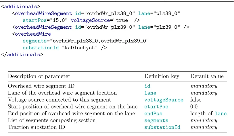
Each overhead wire segment (on regular, i.e. non-internal lanes) needs to be defined as an “additional object”, using additional file syntax. The syntax for the definition of both, an overhead wire segment and overhead wire section is demonstrated in Listing2. The position of
an overhead wire segment depends on the defined SUMOlane and the overhead wire section
needs to be connected to the specific traction substation by the parametersubstationId. All parameters of the overhead wire segment and the overhead wire section are defined in Table2.
Listing 2: Syntax for defining overhead wire on specific lane
<additionals>
<overheadWireSegment id="ovrhdWr_plz38_0" lane="plz38_0"
startPos="15.0" voltageSource="true" />
<overheadWireSegment id="ovrhdWr_plz39_0" lane="plz39_0" /> <overheadWire
segments="ovrhdWr_plz38_0,ovrhdWr_plz39_0"
substationId="NaDlouhych" /> </additionals>
Description of parameter Definition key Default value
Overhead wire segment ID id mandatory
Lane of the overhead wire segment location lane mandatory
Voltage source connected to this segment voltageSource false
Start position of overhead wire segment on the lane startPos 0.0
End position of overhead wire segment on the lane endPos length of lane
List of segments composing section segments mandatory
Traction substation ID substationId mandatory
Table 2: Overhead wire segment parameters
The definition of an overhead wire segment on any internal lane in the additional file is ignored and the building of the overhead wire on the internal lane is provided only by neigh-bouring overhead wire segments on the regular (non-internal) lanes. Overhead wire segments are automatically constructed on internal lanes if any overhead wire segments are specified on both regular lanes that are adjacent to an intersection and these segments are assigned to the same traction substation.
An important boolean parameter of overhead wire segment is voltageSource. If set to
true, the segment is marked as a physical connection point of a traction substation. If there is at least one segment with the defined voltage source, we use Kirchhoff’s laws for the evaluation of the electric circuit (see Section3) and for computing voltage drops due to wire length and vehicle consumption. In the opposite case, we use the definedvoltageof traction substation as a constant voltage on the whole section, neglecting Kirchhoff’s laws.
Listing 3: Example of output of overhead wire segments
<overheadWire-export>
<overheadWireSegment id="ovrhdWr_plz39_0" totalEnergyCharged="5.06"
chargingSteps="5">
<vehicle id="hT13_1" type="hybridTrolleybus"
totalEnergyChargedIntoVehicle="2.23"
chargingBegin="205.00" chargingEnd="206.00">
<step time="205.00" chargingStatus="charging" energyCharged="1.17"
partialCharge="1.17" voltage="750.00" efficiency="0.95"
actualBatteryCapacity="22833.14" maximumBatteryCapacity="46000.00"/> ...
</vehicle> ...
</overheadWireSegment> ...
</overheadWire-export>
2.3
Electric hybrid vehicle
The last component of the simulated network is the hybrid trolleybus or generally electric hybrid vehicle using a pantograph or trolley poles for drawing energy from the overhead wire in our scenario.
The implementation of this new vehicle device is based ondevice.batteryintroduced in [5]. The main motivation of implementation is driven by our need to use overhead wires for charging the onboard battery pack of a hybrid trolleybus and for providing power for the vehicle. Also, the proposed vehicle device shall be able to provide basic power management strategies that influence the energy flows within the vehicle – this way we also overcome the default behaviour of device.battery which would cause drawing of all energy through the battery pack which would have a negative impact on the battery lifespan.
The definition of the hybrid trolleybus using the proposed device objectdevice.elecHybrid in a SUMO route file (*.rou.xml) is similar to the definition of a vehicle usingdevice.battery (for completeness see Listing6and Listing7 in Appendix).
Assigning of thedevice.elecHybridto a vehicle is usually done in the SUMO configuration file (*.sumocfg) – see Listing4. In Listing4 you can see the definition of output as well. An example of output of thedevice.elecHybriditself is then shown in Listing 5.
Listing 4: Syntax for defining the type of a hybrid vehicle
<configuration> ...
<elecHybrid_device>
<device.elecHybrid.explicit value="hT13_1,hT13_2,hT13_3"/> </elecHybrid_device>
<output>
<elecHybrid-output.precision value="2"/>
<overheadWire-output value="overheadWire.out.xml"/> </output>
</configuration>
Listing 5: Example of output of elecHybrid device
<elecHybrid-export maximumBatteryCapacity="46000.00" vehicle="hT13_3">
<timestep time="0.00" energyConsumed="0.00" actualBatteryCapacity="23000.00"
overheadWireSegment="NULL" energyCharged="0.00" current="-nan(ind)"
circuitVoltage="-nan(ind)" speed="0.00" acceleration="0.00" distance="0.00"
x="10945.34" y="9736.09" z="333.51" slope="-1.54" lane="plz37_0"
posOnLane="70.00"/>
<timestep time="1.00" energyConsumed="4.21" actualBatteryCapacity="22999.79"
overheadWireSegment="ovrhdWr_plz37_0" energyCharged="-0.21" current="25.41"
circuitVoltage="596.21" speed="0.80" acceleration="0.80" distance="0.80"
x="10945.84" y="9736.71" z="333.49" slope="-1.54" lane="plz37_0"
posOnLane="70.80"/> ...
</elecHybrid-export>
3
Details of implementation
Since our aim is to deal with the simulation of hybrid trolleybus vehicles, we will describe the details of implementation with the stress on it. The simulated hybrid trolleybuses are usually equipped with a battery pack (with energy storage of size circa 20–60 kW h), which is charged from overhead wires. The traction energy is provided by overhead power lines in case that the vehicle travels under the wires, or drawn from the onboard battery pack in the opposite case.
The amount of energy drawn by the hybrid trolleybus from the overhead wire in one simu-lation step depends both on vehicle parameters and on parameters of the infrastructure. The energy required by each vehicle is the sum of energy needed for movement, energy needed for supplying of auxiliary systems on the board of the vehicle (currently defined with the parameter
constantPowerIntake– see Listing6in Appendix) and energy needed for continuous charging of the battery pack. The first two mentioned contributions are evaluated by the existing energy model of the electric consumption and we do not deal with this model in more detail in this paper. The amount of energy needed to charge the battery pack is influenced by the actual state of charge (SoC). If the demand for energy does not exceed the supply, dependent on the parameters of overhead wires and traction substations, the required amount of energy is fully provided by the overhead wire.
3.1
Overhead wires and traction substation
For simulation of the overhead wire and traction substations we introduce two new classes: MSElecSubstationandMSOverheadWire. The latter represents an overhead wire segment and it has been derived fromMSChargingStation(which in turn is inherited fromMSStoppingPlace class). As there are no required stops to charge a trolleybus, the stopping place functionality is in fact never used — we use the base class only to check the existence of an overhead wire segment on a lane (or more precisely on a certain position of the lane).
There are two main components of the class MSOverheadWire. It is the method
MSOverheadWire::addOverheadWire() and the constructor of MSOverheadWire. During the
creation of the object MSOverheadWire::MSOverheadWire – representing an overhead wire
segment – by the constructor a subroutine addOverheadWire() is called. This
subrou-tine pushes (adds) a pointer to the overhead wire segment into a data member vector
myOverheadWireSegments as the part of an object of class MSElecSubstation, and option-ally creates some circuit Elements with relevant Nodes. Circuit,ElementandNodeare classes of a built-in circuit solver based on work of Essam et al. [1].
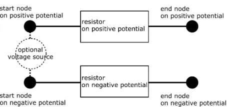
In the case of trolleybuses, there are two overhead wires3, the first on the positive
poten-tial and the second on the negative potenpoten-tial. For this reason, each overhead wire segment (corresponding to single SUMO roadlane) is composed of two resistor Elements (representing a resistance of the overhead wire with the positive potential and with the negative potential respectively) and of four Nodes (each resistor is connected to the start node and the end node). These Nodes are shared with neighboring segments of the overhead wire. Optionally, there could be a voltage source Element between two Nodes (each assigned to a different potential – positive one and negative one). For better understanding, the scheme of the electric circuit corresponding to one overhead wire segment is depicted in Figure2.
Figure 2: Scheme of the part of the electric circuit corresponding to the overhead wire segment on a selected lane.
The resistance R of resistor element on the positive or negative potential of the overhead wire segment is dependent on the overhead wire segment lengthdwith relation
R= ρ Sd,
whereρis resistivity of the overhead wire material andSis the cross-section of the wire. Default values are set asρCu= 1.69×10⁻⁸Ω m andS = 1.5×10⁻⁴m2.
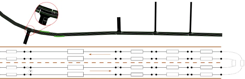
An example of a basic overhead wire circuit after initialization and before adding a vehicle withdevice.elecHybridis depicted in Figure 3.
Figure 3: Scheme of the electric circuit corresponding to the overhead wire on a selected route. (A detail to GUI shapes of overhead wires is zoomed.)
3.2
Vehicle device elecHybrid
The implementation of device.elecHybrid is slightly different for the microscopic mode and
for the mesoscopic mode due to different hook methods being available for each of the simulation modes.
3.2.1 Microscopic elecHybrid
The basic power management of the vehicle and the management of trolleybus parts in the
circuit is in the case of micro-simulation handled by MSDevice ElecHybrid::notifeMove()
method. First, attention is paid to the correct detection of possible change in overhead wire segments. Moreover, it is possible to use an overhead wire segment on the neighboring lane (of the same direction), since such behavior is typical for the real situation as well.
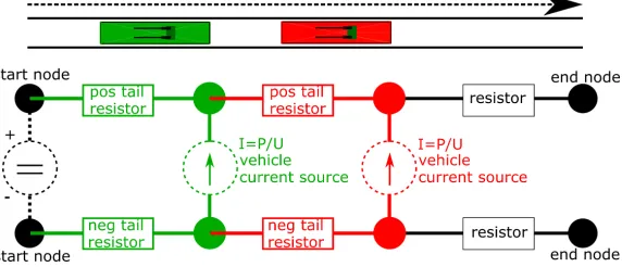
After the successful overhead wire detection, the traction substation that feeds the wire is identified. Then, it is necessary to connect the vehicle to the electric circuit described in Section 3.1. Each vehicle equipped bydevice.elecHybrid and using overhead wires is represented in the electric circuit as a current source Element. This representation allows us to simulate the consumption of the trolleybus as an electrical appliance and ensures the possibility to extend the simulation to handle energy recuperation inside the overhead wire circuit in the future. The current source Element is connected to the circuit with the help of two additional circuit Nodes and two resistor Elements that correspond to overhead wire resistance (the wire on the positive and negative potential is divided into two segments by Nodes of the added vehicle). The scheme of the connection is depicted in Figure4.
Figure 4: Scheme of the connection of two vehicles withdevice.elecHybrid to the overhead wire circuit.
3.2.2 Mesoscopic elecHybrid
In the mesoscopic mode, a simplified management of the on-board energy storage and the simplified co-operation between the vehicle and overhead wires is implemented in meth-odsMSDevice elecHybrid::notifyEnter()andMSDevice elecHybrid::notifyLeave(). In comparison with the microscopic simulation, inputs of the model of the electric energy con-sumption are mean values of entered parameters (speed, acceleration, ...) on a meso-segment of the lane.
4
Evaluation and Results
In this section we discuss the differences between the approach using Kirchhoff’s laws and the approach assuming the same constant voltage everywhere on the overhead wire from SUMO user point of view. The former approach enables to consider e.g. voltage drops, but it requires more computational time in the comparison to the latter approach.
An example of evaluation of the overhead wire voltage, current drawn from the overhead wire by the hybrid trolleybus, and the electric power of the hybrid trolleybus is depicted in
Figure 5. These results are obtained by the simulation employing Kirchhoff’s laws. You can
see the non-constant voltage on the overhead wire. It influences values of the current, because the product of the voltage and current is equaled to the electric input power.
On the other hand, employing of Kirchhoff’s laws in the simulation strongly influences the computational time. A comparison of a computational time (measured on a personal computer with Intel Core i7, 2.3 Ghz) can be seen in Figure6. We depict a duration of simulation without any surrounding traffic in the left graph of Figure6and with a surrounding traffic (1000 cars) in the right graph of Figure6. The comparison assumes the worst case — all vehicles equipped bydevice.elecHybridare moving under the same overhead wire section (thus the solution of the electric circuit is the most complicated).
In the reference implementation we solve the circuit in each simulation step separately for
each vehicle equipped by device.elecHybrid. A simplification that employs a lazy circuit
Figure 5: Example values of electric quantities logged by a hybrid trolleybus vehicle. Note that the peak power consumption of 300 kW is due to combined charging of the battery pack and acceleration of the vehicle.
Figure 6: A comparison of the execution time in dependency on number of vehicles equipped by device.elecHybrid employing Kirchhoff’s laws (blue line) and assuming constant voltage (red line), without any surrounding traffic (left) and with the surrounding traffic incorporating 1000 cars (right).
5
Conclusion
We have proposed novel vehicledevice.elecHybridand new infrastructure objects – the over-head wire and the traction station. With these instruments, we are able to simulate hybrid trolleybus vehicles and their consumption with stress on electric quantities, such the electric current and electric voltage.
with different parameters), a supercapacitor pack (excellent short-time energy storage), an on-board electric generator (i.e. “series hybrid”, generator powered by diesel/gas/. . . ), or a fuel cell or another alternative fuel technology. Moreover, it is important to handle different charging
modes like opportunity charging (with using the already implementedchargingStation),
in-motion charging (using overhead wires or dynamic chargingStation) or charging using
on-board devices (e.g. electric generator).
With new device.elecHybridwe are able to use basic power management strategies that
influence the maximum amount of energy drawn by a vehicle. Ideally, it shall be possible to use a more advanced collaborative strategy to manage energy transfer between vehicles or between vehicles and traction substations. This can be a topic of further work, as well as the acceleration of the circuit network solver closely discussed at the end of Section4.
6
Acknowledgments
This research has been supported by the Ministry of Education, Youth and Sports of the Czech Republic under the project OP VVV Electrical Engineering Technologies with High-Level of Embedded Intelligence CZ.02.1.010.00.018 0690009855 and by UWB Student grant project no. SGS-2018-009.
Appendix
Example of syntax for initializing vehicle equipped withdevice.elecHybrid
Listing 6: Syntax for defining the type of a hybrid vehicle
<routes>
<vType id="hybridTrolleybus" accel="0.7" decel="1.0" length="12"
maxSpeed="18.0" sigma="0.0" minGap="2.5" color="0,1,0"
emissionClass="Energy/unknown" vClass="bus" guiShape="bus/trolley"> <param key="maximumBatteryCapacity" value="46000"/>
<param key="vehicleMass" value="13000"/> <param key="frontSurfaceArea" value="7.5"/> <param key="airDragCoefficient" value="0.59"/> <param key="internalMomentOfInertia" value="0.01"/> <param key="radialDragCoefficient" value="0.5"/> <param key="rollDragCoefficient" value="0.061"/> <param key="constantPowerIntake" value="6000"/> <param key="propulsionEfficiency" value="0.9"/> <param key="recuperationEfficiency" value="0.9"/> </vType>
</routes>
Listing 7: Syntax for hybrid trolleybus vehicle definition
<routes>
<vehicle id="hT13_1" type="hybridTrolleybus" depart="1.00" departLane="0"
<param key="actualBatteryCapacity" value="23000"/>
<stop busStop="busstop_8417432" duration="15.00" until="60"/> ...
<stop busStop="busstop_9965301" duration="180.00" until="2400"/> </vehicle>
</routes>
References
[1] Ahmad Essam, Ahmad Khaled, Omnia Zakaria, and Mary Nader. Circuits Solver Operation Manual, 2017. Available: www.github.com/rka97/Circuits-Solver [Accessed: 12-Feb-2019]. [2] The European Commission. A European Strategy for Low-Emission Mobility. The European
Commission, Brussels, 2016.
[3] Ga¨el Guennebaud, Benoˆıt Jacob, et al. Eigen v3. http://eigen.tuxfamily.org, 2010.
[4] Chung-Wen Ho, A Ruehli, and Pierce Brennan. The modified nodal approach to network analysis. IEEE Transactions on circuits and systems, 22(6):504–509, 1975.
[5] Tam´as Kurczveil, Pablo ´Alvarez L´opez, and Eckehard Schnieder. Implementation of an energy model and a charging infrastructure in sumo. In Michael Behrisch, Daniel Krajzewicz, and Melanie Weber, editors, Simulation of Urban Mobility, pages 33–43, Berlin, Heidelberg, 2014. Springer Berlin Heidelberg.
[6] Pablo Alvarez Lopez, Michael Behrisch, Laura Bieker-Walz, Jakob Erdmann, Yun-Pang Fl¨otter¨od, Robert Hilbrich, Leonhard L¨ucken, Johannes Rummel, Peter Wagner, and Evamarie WieBner. Mi-croscopic traffic simulation using sumo. InThe 21st IEEE International Conference on Intelligent Transportation Systems. IEEE, 2018.
[7] Khizir Mahmud and Graham E Town. A review of computer tools for modeling electric vehicle energy requirements and their impact on power distribution networks. Applied Energy, 172:337– 359, 2016.
[8] Ricardo Maia, Marco Silva, Rui Ara´ujo, and Urbano Nunes. Electric vehicle simulator for energy consumption studies in electric mobility systems. InIntegrated and Sustainable Transportation System (FISTS), 2011 IEEE Forum on, pages 227–232. IEEE, 2011.
[9] Deborah Perrotta, Jos´e Luiz Macedo, Rosaldo J. F. Rossetti, Jo˜ao Luiz Afonso, Zafeiris Kokkino-genis, and Bernardo Ribeiro. Driver attitude and its influence on the energy waste of electric buses. In Michael Behrisch, Daniel Krajzewicz, and Melanie Weber, editors,Simulation of Urban Mobility, pages 99–108, Berlin, Heidelberg, 2014. Springer Berlin Heidelberg.
[10] Insaf Sagaama, Amine Kchiche, Wassim Trojet, and Farouk Kamoun. Proposal of more accurate energy model of electric vehicle for sumo. In2018 14th International Wireless Communications & Mobile Computing Conference (IWCMC), pages 464–469. IEEE, 2018.
[11] Mohammed Salih, D Baumeister, M Wazifehdust, P Steinbusch, M Zdrallek, S Mour, P Deskovic, T K¨ull, and C Troullier. Impact assessment of integrating novel battery-trolleybuses, pv units and ev charging stations in a dc trolleybus network. In2nd E-Mobility Power System Integration Symposium, 2018.
[12] Girts Stana and Viesturs Brazis. Trolleybus motion simulation by dealing with overhead dc network energy transmission losses. In2017 18th International Scientific Conference on Electric Power Engineering (EPE), pages 1–6. IEEE, 2017.