NUMERICAL SIMULATION OF FLUID FLOW AND HEAT TRANSFER
IN A MEMS-BASED MICRO CHANNEL HEAT SINK
Md. Farhad Ismail
a,*, M.A.I. Rashid
b, M. Mahbub
b aSchool of Engineering Science, Simon Fraser University, BC, Canada V3T 0A3 b
Bangladesh University of Engineering & Technology (BUET), Dhaka, 1000, Bangladesh
A
BSTRACTCarbon nanotube (CNT) has been proven to be an effective material for the thermal management of MEMS-based devices due to its superior thermal conductivity. At the same time, micro-channel heat-sinks are widely used in electronic products as a high performance heat transfer device because of its simple construction, easy fabrication process and effective heat removal capability. A numerical study has been carried out to investigate the thermal-fluid characteristics of the aligned and staggered MWCNT (multi walled CNT) based micro pin fins having 650 µm long with hydraulic diameter of ~130 µm. Average heat transfer coefficients have been obtained for effective heat fluxes ranging from 50 to 130 W and Reynolds numbers from 14 to 160. The influence of various fluids, fluid velocity; fluid conductivity, fin material, fin conductivity, fin geometry and fin orientations on cooling effects have also been investigated and compared in this study.
Keywords: Cooling effects, fin orientation, MEMS, MWCNT, Thermal-fluid characteristics.
1. INTRODUCTION
Electronic devices require more effective thermal enhancement system to maintain its operating temperatures at a satisfactory level due to the increase of power density. Micro-channel heat sinks provide an effective way of cooling microchips. Micro-channels provide enhanced heat transfer ability due to having a smaller hydraulic diameter. Numerous authors have investigated CNTs as thermal interface materials in micro-channels for cooling. Carbon nanotubes (CNTs) were discovered in 1991. They are allotropes of carbon with a nanostructure that have a length-to-diameter ratio greater than 1000000. A CNT is formed when the two-dimensional sheet of graphene is rolled into a seamless cylinder. Based on the chemical arrangement of carbon atoms, a discrete number of unique CNTs can be formed. A thermal conductivity of CNT up to 6600W/m·K has been reported. Copper, silver and gold, which are some of the best known thermally conductive materials, have thermal conductivities of 400 W/m·K, 430 W/m·K and 320 W/m·K at room temperature respectively. As a new material, CNTs are attracting more and more attention, and they are potentially very useful in nanotechnology, electronics, optics and aeronautics (Xu et al., 2006; Liu et al., 2008; Zhu et al., 2005; Hone, 2000).
Single phase cooling using CNTs with water as cooling medium on the other hand was researched by Mo et al. (2005). They applied different heat rates to the base of the silicon microchannel while holding the pressure drop across the device constant. In general we found that the presence of MWNTs results in enhanced heat removal from the silicon minichannel. In Fig. 1, the technique of heat transfer with CNT is shown.
Fig. 1 Heat transfer by CNT
Flows over intermediate size pin fin banks have been commonly used in turbine cooling systems to increase the internal heat transfer characteristics. The pin height-to-diameter, H/d, ratios of typical heat sinks used for such applications were between ½ and 4. A concise review of staggered array arrangements for intermediate pin sizes was provided by Armstrong et al. (1988). The vast majority of studies on intermediate size pin fins were performed with air at turbulent flow conditions. It was found that the average heat transfer coefficient for relatively short pin fins was lower than for long cylinders. The reduction was attributed to a decrease in the near-wall cylinder heat transfer relative to the heat transfer away from the wall where the cylinder was unaffected by the end-walls. Thus, at low Reynolds number the effect of endwalls is expected to be prevalent over a significantly broader range of H/d values compared to high Reynolds numbers. However, the extent of this effect can currently not be fully determined since very little data are available on laminar Reynolds numbers (especially for Re<100).
*Corresponding Author, E-mail: [email protected]
Frontiers in Heat and Mass Transfer
Micro-channel cooler is a very promising approach to meet the requirements of microelectronics package cooling. A lot of investigations about micro-channels have been undertaken in the past years. However, as the trends in the electronics industry moves towards higher packaging density, the high-pressure drop problem limits the performance of traditional silicon heat sink. Replacing the silicon fins with nanotube fins to enhance the thermal exchange rate between cooling liquid and substrate is one way to overcome this problem. Channels are etched and covered by plexiglass on the top and ultimately formed a complete structure. The basic principle of micro-channel heatsink is that bottom is in touch with the heat and fluid flows through the entrance to the export to take away heat. In practice, with increasing heat, when the micro-cooler maximum temperature exceeds the fluid’s temperature, convection heat is generated between wall and fluid until the heat balance is stabilized and micro-cooler works into the stable working condition (Wang et al., 2009; Zhong et al. , 2007) Replacing the silicon fins with nanotube fins or growing aligned nanotubes on the whole substrate to enhance the thermal exchange rate between cooling liquid and substrate is one way to overcome this problem (Kordas et al., 2007; Dietz et al., 2008; Jakaboski et al. ,2004). To promote a good thermal contact on the interfaces between the multi-walled CNTs and their growth substrate, adhesion layers consisting titanium, molybdenum or chromium are often deposited onto the substrates before fabrication (Hone, 200; Liu, 2008; Xu, 2006). Other studies showed that the multi-walled CNT free ends’ interface had a significantly higher resistance compared to that at the multi-walled CNT growth substrate interface; and this problem could be solved by using a thin layer of indium to weld the multi-walled CNT ends to the substrate (Tong et al., 2007).
2. CNT BASED MICRO-COOLER
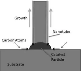
CNT as fin material was introduced by Liu [2] and his research group in 2004. By combination of the high thermal conductivity material with the high heat transfer efficiency structure, it is a tempting and promising scheme for thermal issues in electronics. A bare silicon chip was chosen as the substrate. In chemical vapor decomposition process, nano-particles of a catalyst are deposited on a substrate surface before being inserted into a tube furnace. A carbon containing gas, such as acetylene then flows through the tube furnace at high temperatures, leading to decomposition of the gas into carbon atoms. The nano-particles of catalyst attract these carbon atoms, initiating CNT growth (Thostenson 2001). This process is illustrated in Figure 2. After CVD synthesis, CNTs array (Kolasinski, 2006; He et al., 2007) was grown from the catalyst as cooling fins (Fig. 2). Finally, a lid was bonded to seal the CNTs and form the microchannels.
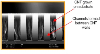
Figure 3 shows the SEM pictures of the one-dimensional and two-dimensional CNT array respectively. Carbon nanotubes are grown using a vapor-liquid-solid (VLS) technique. VLS describes the action of liquid catalyst particles becoming super saturated with a vapor and the subsequent forming a solid crystal structure. Specifically, growth occurs via a process of diffusion of the precursor into the catalyst particle, adsorption of reactive species onto the catalyst surface, and subsequent surface reactions with the precursors to create the nanotube. This process is illustrated in Fig. 2. Typically, transition metals such as Fe, Ni, Co, or Mo are used as catalysts for carbon nanotube synthesis. These metals have proven effective because of their ability to absorb the carbon based reactant gases. The adhesion of the CNT to its growth
surface is a function of the catalyst’s adhesion to the substrate and the CNT’s adhesion to the catalyst (Shenoy et al., 2011).
Fig. 2 Growth of carbon nano tube on the Silicon substrate
Fig. 3 SEM picture of CNT with grown on a flat silicon substrate (Liu et al., 2008).
3. CFD SIMULATION MODEL
3.1. Theoretical Analysis
A coolant flows through a micro channel heat sink takes away heat from heat component attached below (constant heat flux). The top face is made of insulated material (such as glass) and the bottom material is silicon. The heat transfer contains two parts: conduction in the solid and convection between the solid and coolants. By continuities of temperature and heat flux, the solid region and fluid region are coupled. Some simplifying assumptions are considered as follows:
(1) Flow is assumed to be laminar; (2) Incompressible flow;
(3) Hydro dynamically and thermally fully developed flow; (4) No radiation of the wall;
(5) Negligible convection of air out of the cooling assembly; (6) Constant solid and fluid properties.
(7) A no-slip boundary condition and no interfacial resistance are applied to each of the interfaces
In the case of devices with MWCNTs, even though in reality the MWCNTs act as a nano-structured porous medium, the software limits us to assume them as a solid entity (Shenoy et al., 2011). The fins are considered as a bulk medium with anisotropic thermal conductivity 300 W/m-k in the vertical z-direction and 30W/m-K in the horizontal x- and y-direction (Wang et al., 2009; Ismail et al., 2011).
3.2.Mathematical Model
In this study, the boundary conditions and computational domain are considered for three dimensional cases. Tin is inlet temperature of the
straight or parallel plate fins were investigated and compared with elliptical pin fin heatsink in their work. In this study, heat transfer capacity of aligned and staggered micro-pin fin array is investigated. For this comparison the following assumptions are made: ST=SL=1.5 D;
where D is nano-tube diameter, 1 mm. The height of each nano-tube is, H=0.65 mm. The comparison is made for 36 micro pin fins. Kosar et el., 2005-2006 gave detailed description for measuring the hydraulic diameter (for compact heat exchanger) of the channel.
Fig. 4 3D computational model for aligned circular pin-fin heat sink
Fig. 5 Typical Model of a compact heat exchanger
Fig. 6 Model of the in line and staggered pin fin arrangement.
The energy conservation equation, which can theoretically predict the value of temperature rise between the inlet and outlet, is used for simulation validation in this work. Following the adiabatic boundary conditions in this simulation, the energy supplied by the chip should be equal to the heat removed by the water Eq. (1) and thermal resistance is measured using the following equations Eq. (2).
, ( )
fVcp f Tout Tin Wchip
ρ − = (1)
( base in) /
R= T −T Q (2)
where, V is volume flow rate, Cp,f is specific heat of fluid at constant
pressure, Tout is outlet fluid temperature, Tin is inlet fluid temperature
(20°C); ρ is fluid density and WChip or Q is power generated from chip
in Watt.
Fig. 7 Comparison between CFD simulation results and experimental result
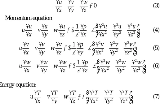
For the three dimensional analyses the mathematical equations can be written in the following form-
Continuity equation-
u v w 0
x y z
∂ +∂ +∂ =
∂ ∂ ∂
(3) Momentum equation
2 2 2
2 2 2
1
u u u p u u u
u v w
x y z ρ x ν x y z
∂ + ∂ + ∂ = − ∂ + ∂ +∂ +∂
∂ ∂ ∂ ∂ ∂ ∂ ∂ (4)
2 2 2
2 2 2
1
v v v p v v v
u v w
x y z ρ y ν x y z
∂ + ∂ + ∂ = − ∂ + ∂ +∂ +∂
∂ ∂ ∂ ∂ ∂ ∂ ∂ (5)
2 2 2
2 2 2
1
w w w p w w w
u v w
x y z ρ z ν x y z
∂ + ∂ + ∂ = − ∂ + ∂ +∂ +∂
∂ ∂ ∂ ∂ ∂ ∂ ∂ (6)
Energy equation:
2 2 2
2 2 2
T T T T T T
u v w
x y z α x y z
∂ + ∂ + ∂ = ∂ +∂ +∂
∂ ∂ ∂ ∂ ∂ ∂ (7)
4. MESH GENERATION
Conjugate heat transfer module is used to treat the solid and fluid as a unitary computational domain, and to solve the above governing equations simultaneously. The mesh in every channel should be fine enough (Fig.8), thermal conductivity of MWCNT is very high in z-direction (400 W/m-K) and low in x and y z-direction (40 W/m-K). Different kinds of mesh numbers had been carried out and compared with the maximum fin temperature. The comparison graph is showed that there is not much difference in the results. So, the influence of amount of mesh can be neglected in the certain region.
Fig. 8 Mesh sensitivity test-maximum fin temperature for different mesh number
5. NUMERICAL SIMULATION
The generated heat of CPU/Chip is dissipated by the coolant. Therefore, it is also necessary to understand the coolant temperature distribution flowing through the mini-fin heat sink.
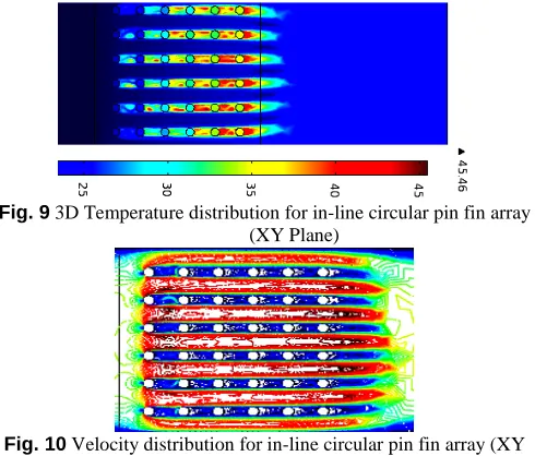
The lowest and highest temperatures occur at the entrance region and outlet region of the heat sink, respectively. Fluid temperature tends to increase as the fluid flows close to the outlet region. This is because the heat transfer rate from the heat sink to the coolant increases. The low temperature region of the heat sink occurs at the entrance region. This is because the heat transfer coefficient increases in this region. From Fig. 9-14 we different types of investigation are shown for two types of fin arrangements.
Fig. 93D Temperature distribution for in-line circular pin fin array (XY Plane)
Fig. 10 Velocity distribution for in-line circular pin fin array (XY Plane)
Fig. 11Pressure contour for in-line circular pin fin array (XY Plane)
Fig. 12Temperature distribution for staggered circular pin fin array (XY Plane)
Fig. 13 Velocity Contour for staggered circular pin fin array (XY Plane)
Fig. 14 Pressure Contour for staggered circular pin fin array (XY Plane)
6. SIMULATION RESULTS AND ANALYSIS
Here three dimensional models are simulated for different types of fin geometry; different fluid and fluid velocity. The inlet velocity is set 200 C. The simulation is conducted for constant heat flux condition and the heat flux range is varied from 15 W/cm2 to 40 W/ cm2.
6.1.Effects of fin material:
Fig. 15 Maximum fin temperature variation with the Velocity for different material
Fig. 16Variation of Nusselt Number for different conductivity of CNT
6.2.Effects of heat flux and fluid:
Maximum thermal resistance as a function of heat flux is also investigated here considering water as cooling fluid and assuming the velocity 0.75 m/s (Fig. 17). The heat transfer capability is dependent on the properties of working fluid, the most frequently used coolant in the micro channel heat sink is water. Better results may be possible with other fluids. So, one of the methods for changing heat transfer is to use the different working fluids. Here, the model was simulated for four fluids- water, ethylene glycol, FC-72, FC-77- from 3M Company (Fig.18).
Fig. 17 Variation of thermal resistance for different heat flux
Fig. 18 Variation of thermal resistance for different fluid velocity
6.3.Effects of heat sink geometry
It is investigated that the maximum fin temperature is decreased with the increase of the number of fin array (Fig. 19). But after a certain increase of array the temperature of the assembly again increases. It is because the coolant does not get enough space to take the heat from the array. The model was also investigated for different fin height and channel width (Fig. 20-21).
Fig. 19 Variation of Fin temperature with the Number of fin array
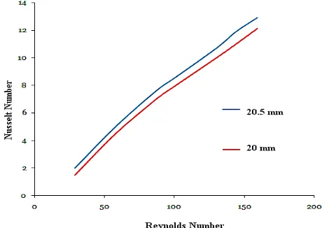
Fig. 21 Variation of Nusselt Number for different width of the channel
7. DISCUSSION
This simulation work presents the thermal performance of a MEMS based micro heat sink. Figure 22 shows the difference between the available theoretical value of Nusselt number (Zukauskas et al., 1972) and our numerical results. Figure 23 shows that staggered arrangement of CNT fins show greater heat transfer performance.
Fig. 22 Comparison between theoretical and current numerical result
Fig. 23 Variation of Nusselt Number for different configuration of CNT based fins.
In order to present the numerical results in a more general manner and to perform comparison with large scale correlations, the Nusselt Number is derived from the heat transfer coefficient data. The average Nusselt numbers are shown in Fig. 22 as a function of the Reynolds number along with correlations (Zukauskas, 1972) obtained on large scale systems. While attempting to compare the Nusselt number obtained in the current study with the available correlations reported in archival literature it is apparent that very few correlations provide a proper base for comparison, particularly, for flow over intermediate size pin fins at Reynolds numbers ranging from ~5 to ~160. Correlations developed for pin fins between 1< (H/d) <4 are mostly available for turbulent Reynolds numbers (Çengel et al., 2001; Panton, 1996) and were obtained based on experimental results using air.
A remarkable number of studies have been carried out to find the correlations for laminar flow across long tubes/pin fins to evaluate the Nusselt number. It can be seen that at low Reynolds number the numerical Nusselt numbers are considerably lower than all other correlations by a large factor. Zukauskas et al. (1972) correlations were recommended for long tubes and do not account for endwall effects (endwall effects account for the interaction between the pin fins and the base on which they reside-top and bottom walls). The low Nusselt number values (compared to large scale correlations’ prediction) can be linked to endwall effects, which result in lower heat transfer coefficients for the intermediate pins compared to long pin fins at reduced Reynolds numbers (Kosar et al., 2005). An additional factor that might adversely contribute to the lower heat transfer coefficients at low Reynolds numbers arises from a delay in flow separation. For long cylinders, flow separation commences at Re~4 leading to a formation of two attached steady standing eddies (Shair et al., 1963 ), which increases the heat transfer coefficient for fins in the following row and the average heat transfer coefficient. Flow over a cylinder confined by two endwalls with a finite and relatively small aspect ratio is modified by the presence of the walls in a manner which tends to delay separation to higher Reynolds number (Nishioka et al., 1965; Damerow et al., 1972; Metzger et al., 1982). Furthermore, the more compact the tube bank is, the larger the Re number range is in which non-separating flow is preserved (Peles et al., 2005). Thus, heat transfer enhancement is delayed to higher Reynolds number as H/d and the pitch-to-diameter ratio diminish (Kosar et al., 2005).
coolant temperature and heat sink temperature, higher heat flux gives heat transfer coefficient higher than those lower ones. Figure 23 also shows the variation of the average heat transfer coefficient calculated from the present study increases with increase of coolant Reynolds number of various geometrical configurations. It is seen that staggered configuration have showed better performance than that of in line CNT configuration. It is due to the increase of turbulence inside the staggered array.
8. CONCLUSIONS
Effective heat removal rate and cooling performance of MEMS-based devices having different types of fin configuration have been investigated numerically in this paper. Effect of coolant conductivity, coolant velocity, heat generation, fin material, fin arrangements etc. is also considered. It is found that water (de-ionized) shows better thermal performance among all other coolants considered in this paper. The results also indicate that the cooling efficiency is dependent very much on the number of fin rows, fin height, fin material and fin arrangements. More fin rows is beneficial for cooling capability. The results obtained in this work may be very useful for the selection of coolant used in CNT based micro-fin array. The advantage of using a carbon nano-structured based pin fin heat-sink instead of the Al/Cu-based pin fin heat sink is that it reduces the weight and the dimensions of it. Despite low weight and volume consumption of carbon nanostructures, they show high mechanical and thermal strengths which increase the reliability of electronic devices.
ACKNOWLEDGEMENT
This work was supported by the department of Mechanical engineering of Bangladesh University of Engineering & Technology (BUET).
REFERENCES
Armstrong, J., and Winstanley, D., 1988, “A Review of Staggered Array Pin Fin Heat Transfer for Turbine Cooling Applications,” ASME, International Gas Turbine Conference and Exhibition, 32nd, Anaheim, CA, May 31-June 4, 1987, pp.12.
http://dx.doi.org/10.1115/1.3262173
Brigham, B. A., and Van Fossen, G. J., 1984, “Length to Diameter Ratio and Row Number Effects in Short Pin Fin Heat Transfer,” ASME J. Eng. GasTurbines Power, 106(1), pp. 241–245.
http://dx.doi.org/10.1115/1.3239541
Çengel, Y. A., and Turner, R. H., 2001, Fundamentals of Thermal-Fluids Sciences, McGraw Hill, Boston, pp. 575–577.
Chapman, C.L., Lee, S., and Schmidt, B.L., 1994, “Thermal Performance of an Elliptical Pin Fin Heatsink,” Proceedings of the Tenth IEEE Semiconductor Thermal Measurement and Management Symposium (Semi-Therm), San José, California, February 1-3, pp. 24-31.
http://dx.doi.org/10.1109/STHERM.1994.288998
Damerow, W. P., Murtaugh, J. C., and Burgraf, F., 1972, “Experimental and Analytical Investigation of the Coolant Flow Characteristics in Cooled Turbine Airfoils,” NASA Contract Rep. NASA CR, CR-120883.
Dietz, C.R., and Joshi, Y.K., 2008, “Single-phase forced convection in microchannels with carbon nanotubes for electronics cooling applications,” Nanoscale and Microscale Thermophysical Engineering. 12 (3), 251–271.
http://dx.doi.org/10.1080/15567260802171937
He, X., Wu, F., Zheng, M., 2007, “The synthesis of carbon nanoballs and its electrochemical performance,” Diamond and Related Material, 16, 311.
http://dx.doi.org/10.1016/j.diamond.2006.06.011
Hone J., 2004, “Carbon Nanotubes: Thermal properties,” Dekker Encyclopedia of Nanoscience and nanotechnology, pp. 603-610.
Ismail, M.F., Rashid, M.A.I., Mahbub, M., 2011, “CFD Analysis for Optimum Thermal Design of a Carbon Nanotube based Micro-channel Heatsink”, Engineering Journal (EJMET, Thailand), Vol. 15, No. 4, ID- 171, 2011.
http://dx.doi.org/10.4186/ej.2011.15.4.11
Jakaboski, B.E., and Rightley, M., 2004, “Forced convection in a microchannel heat sink using carbon nanotubes for heat transfer enhancement,” Heat Transfer, vol. 2, pp. 227–233.
http://dx.doi.org/10.1115/IMECE2004-60876
Jun X, Timothy S., 2006, “Enhancement of thermal interface materials with carbon nanotube arrays,” International Journal of Heat and Mass Transfer, 49, pp. 1658–1666.
http://dx.doi.org/10.1016/j.ijheatmasstransfer.2005.09.039
Kordas, K., Toth, G., Moilanen, P., Kumpumaki, M., and Uusimaki, A., 2007, “Chip cooling with integreted carbon nanotube microfin architecture”, Applied Physics Letters 90, 123105.
http://dx.doi.org/10.1063/1.2714281
Kolasinski, K.W., 2006, “Catalytic growth of nanowires: Vapor-liquid-solid, vaporsolid-Vapor-liquid-solid, solution-liquid-solid and solid-liquid-solid growth,” Current Opinion in Solid State & Materials Science, 10, 182. http://dx.doi.org/10.1016/j.cossms.2007.03.002
Kosar, A., Mishra, C., and Peles, Y., 2005, “Laminar Flow Across a Bank of Low Aspect Ratio Micro Pin Fins,” ASME J. Fluids Eng., 127(3), pp. 419–430.
http://dx.doi.org/10.1115/1.1900139
Kosar, A., and Peles, Y., 2006, “Thermal-Hydraulic Performance of MEMS-based Pin Fin Heat Sink,” ASME Journal of Heat Mass Transfer, 128, pp. 121-131.
http://dx.doi.org/10.1115/1.2137760
Liu, J., Fu, Y, Wang, and T., 2008, “Recent Progress of Carbon Nanotubes as Cooling Fins in Electronic Packaging”, International Conference on Electronic Packaging Technology & High Density Packaging.
http://dx.doi.org/10.1109/ICEPT.2008.4607067
Metzger, D. E., Fan, Z. N., and Shepard, W. B., 1982, “Pressure Loss and Heat Transfer through Multiple Rows of Short Pin Fins,” Proceedings of the 7th International Heat Transfer Conference, Munich, Germany, Vol. 3, pp. 137–142.
Nishioka, M., and Sato, H., 1973, “Measurements of Velocity Distributions in the Wake of a Circular Cylinder at Low Reynolds Number,” J. Fluid Mech., 65, pp. 97–112.
http://dx.doi.org/10.1017/S0022112074001273
Panton, R., 1996, Incompressible Flow, 2nd ed., Wiley, New York, pp. 384–400.
Peles, Y., Kuo, C. J., Kosar, A., Mishra, C., and Schneider, B., 2005, “Forced Convective Heat Transfer Across a Pin Fin Micro Heat Exchanger,” Int. J. Heat Mass Transfer , 48(17), pp. 3615–3627. http://dx.doi.org/10.1016/j.ijheatmasstransfer.2005.03.017
Shair, F. H., Grove, A. S., Petersen, E. E., and Acrivos, A., 1963, “The Effect of Confining Walls on the Stability of the Steady Wake Behind a Circular Cylinder,” J. Fluid Mech., 17, pp. 546–550.
http://dx.doi.org/10.1017/S0022112063001506
Shenoy, S., Tullius, J.F., and Bayazitoglu, Y., 2011, "Minichannels with carbon nanotube structured surfaces for cooling applications," International Journal of Heat and Mass Transfer 54, pp.5379–5385. http://dx.doi.org/10.1016/j.ijheatmasstransfer.2011.08.005
Steinke, M.E., Kandlikar, S.G., 2006, “Single-phase liquid heat transfer in plain and enhanced microchannels,” Proceedings of the ASME 4th International Conference on Nanochannels, Microchannels and Minichannels, Parts A and B, ASME, Limerick, Ireland, pp. 943–951. http://dx.doi.org/10.1115/ICNMM2006-96227
Tong T., Zhao Y., Delzeit L., Kashani A., Meyyappan M. and Majumdar A., “Dense Vertically Aligned Multiwalled Carbon Nanotube Arrays as Thermal Interface Materials”, IEEE Transactions
on Components and Packaging Technologies, vol. 30 (2007), pp. 92-99. http://dx.doi.org/10.1109/TCAPT.2007.892079
Thostenson, Erik T., Zhifeng Ren, and Tsu-Wei Chou. "Advances in the Science and Technology of Carbon Nanotubes and Their Composites: A Review." CompositesScience and Technology 61 (2001): 1899-912.
http://dx.doi.org/10.1016/S0266-3538(01)00094-X
Wang, B. X. and Peng , X.F., 1994, “Experimental investigation on
liquid forced convection heat transfer through microchannels,” Int. J. Heat and Mass Transfer, vol. 37, pp. 73–82.
http://dx.doi.org/10.1016/0017-9310(94)90011-6
Wang, S., Zhang, Y., Fu, Y., Wang, X., Cheng, Z., 2009, “A Study of Heat Transfer Characterstics of the Micro- Channel Heatsink,” International Conference on Electronic Packaging Technology & High Density Packaging, pp.255-259.
Zhimin, M., Raluca, M. , Anderson, J., Eleanor, E.B., Campbell, D., and Liu, J., 2005, “Integrated Nanotube Microcooler for Microelectronics Applications,” Electronic Components and Technology Conference, pp.51-54.
http://dx.doi.org/10.1109/ECTC.2005.1441244
Zhong, X., Yi, F., Johan, L., Zhang, Y., Teng, W., and Zhaonian, C., 2007, “A Study of CFD Simulation for On-chip Cooling with 2D CNT Micro-fin Array,” International Symposium on High Density Packaging and Microsystem Integration , China, pp.442-447.
http://dx.doi.org/10.1109/HDP.2007.4283649
Zhu, L., Y. Sun, J. Xu, Zhang, Z., Hess, D. W. , and Wong, C. P., 2005, “Aligned Carbon Nanotubes for Electrical Interconnect and Thermal Management,” Proceedings of The 55th Electronic Components and Technology Conference, 31 May 2005, Lake Buena Vista, FL USA,pp.44-50.
http://dx.doi.org/10.1109/ECTC.2005.1441243