Organized by G. V. S. E. T., Jaipur. Available Online at www.ijpret.com360
INTERNATIONAL JOURNAL OF PURE AND
APPLIED RESEARCH IN ENGINEERING AND
TECHNOLOGY
A PATH FOR HORIZING YOUR INNOVATIVE WORK
MATHEMATICAL MODELING AND STRESS ANALYSIS OF VALVE GEAR TRAIN OF
DIESEL ENGINE AT VARIABLE VALVE LIFT
R S RAJPUT1, ANSHUL GANGELE2, NEERAJ KUMAR3
1.Research Scholar- Mechanical Engineering Department, Suresh Gyan Vihar University, Jaipur, Rajasthan 2.Professor -Department of Mechanical Engineering, Sandip University, Nashik, Maharashtra.
3.Professor & Head -Department of Mechanical Engineering, Suresh Gyan Vihar University, Jaipur, Rajasthan
Accepted Date: 19/03/2018; Published Date: 01/04/2018
Abstract:Dynamic forces are the results of varying turning moment, vibration and changes in loads on the engine. This leads to massive contact stresses in cam and follower of the engine which is responsible for changes in the timing of valve opening and closing. This paper defines a methodology to estimate the Hertzian contact stresses through the dynamic analysis with the aid of computer simulation (MATLAB). A dynamic force, which leads to wear and loss of power, may be the cause of the premature failure of the system. The inertia forces provide more accurate analysis of stresses of mating parts in line contact, which is crucial in estimation of wear also. The crucial variables, contact loads and relative motion, have been deduced by mathematical modeling of kinematics and dynamics of valve train system. The flat-faced tappet has been used with Polydyne cam profile. This modeling provides estimates of dynamic forces, Hertzian stresses in cam and follower which may prolong the life of engine.
Keywords: Six phase transmission line; fault analysis.
Corresponding Author: R S RAJPUT
Access Online On: www.ijpret.com
How to Cite This Article:
R S Rajput, IJPRET, 2018; Volume 6 (8): 360-368 PAPER-QR CODE
SPECIAL ISSUE FOR
NATIONAL LEVEL CONFERENCE
Organized by G. V. S. E. T., Jaipur. Available Online at www.ijpret.com361 INTRODUCTION
Befitting valve gear train system of any four stroke internal combustion engine is the key to control the operation of inlet and exhaust valves. Due to the strict norms of BIS, it is desirable to minimize the exhaust emission in accordance with engine’s power output and torque [1].
Sudden changes in accelerationresult in greater Hertz pressures in the cam and follower system
[6,15]. These higher Hertz stresses follow the acute subsurface fatigue, which initiates below tenths of millimeters of cam surface. Also considerable sliding wear occurs at lower velocities since the elastohydrodynamic lubrication properties are degenerated leading to higher friction between cam and follower [4, 5, 7, 10, and 11]. Extreme tribological conditions are observed in valve gear train system owing to fluctuations in cycling loading and abrupt change of relative sliding speed. Also the operation of valves is influenced by stiffness and damping characteristics of elements such as valve spring and valve seat, inertia and geometry of components and frictional behavior of mating components. Valve opening and closing is dependent upon the mechanical and dynamic factors, hence to have smooth operation, it relies upon geometry of elements as well as on vibration. Both shape and thickness of fluid-film between cam and follower depend on the applied load and relative speed [12, 13, and 14]. In the current analysis a flat faced follower is used. However the analysis can also be easily exposed to other geometries of followers.
Earlier cams have SHM and Cycloidal motion but nowadays they have polynomial motion of
5th or 6th-order, which gives better performance at high speeds [2, 16].
THE KINEMATIC MODEL OF CAM AND FOLLOWER
In this analysis, a Polydyne [2 and 3] of 6-order is taken. The equation of motion for this cam is:
Lift,
6 5 4 3 64 192 192 64 L Y
(0 ) (1)
Velocity,
6 5 5 4 4 3 3 2 384 960 768 192 L V (2)
Acceleration,
6 4 5 3 4 2 3
2 384 2304 3840 1920
L A (3)
Jerk,
6 3 5 2 4 3
3 768 4608 11520 7680
L J (4)
Where t
=Angular velocity of camshaft = 60
2N
Organized by G. V. S. E. T., Jaipur. Available Online at www.ijpret.com362 = Constant (max. angle of rise or fall)
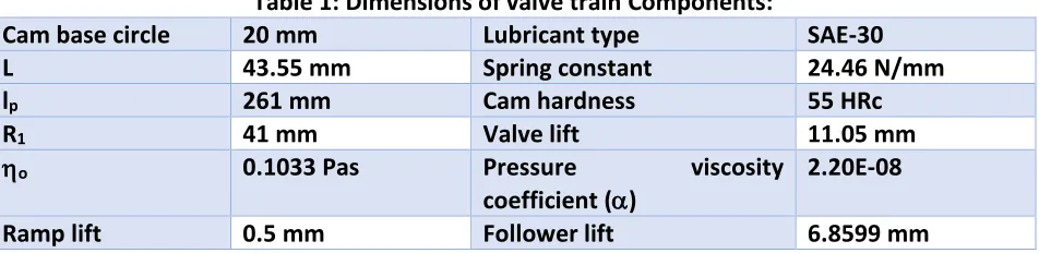
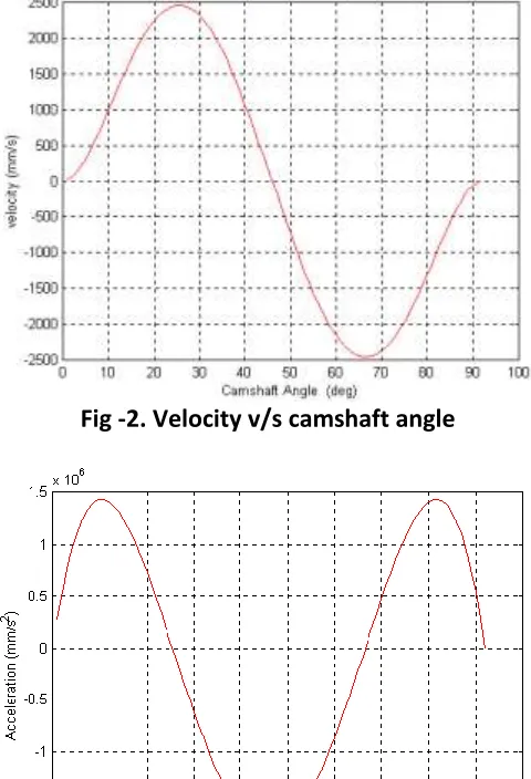
The dimensions and other parameters are given in table-1 below. The pertaining graphs have been obtained through a MATLAB program for the above equations showing displacement, velocity, acceleration and jerk at 3200 rpm.
Table 1: Dimensions of valve train Components:
Cam base circle 20 mm Lubricant type SAE-30
L 43.55 mm Spring constant 24.46 N/mm
lp 261 mm Cam hardness 55 HRc
R1 41 mm Valve lift 11.05 mm
o 0.1033 Pas Pressure viscosity
coefficient ()
2.20E-08
Ramp lift 0.5 mm Follower lift 6.8599 mm
Figure-1 shows the displacement of follower with a maximum value of 6.8599 mm that occurs
at 45o of cam rotation.
Figure-2 shows the velocity (in mm/s) v/s camshaft angle (degree). At 10o, the value of velocity
is 1000 mm/s. maximum velocity occurs at 25o and 66o.
Figure-3 shows acceleration (in mm/s2) v/s camshaft angle. Maximum acceleration occurs at
10o and 45o.
Figure-4 shows jerk (in mm/s3) v/s camshaft angle. Jerk produces shock loads and causes undue
vibrations and stresses. Jerk has been a main source of trouble in earlier cam profiles but in this case jerk is finite and results into smaller shock loads.
Organized by G. V. S. E. T., Jaipur. Available Online at www.ijpret.com363 Fig -2. Velocity v/s camshaft angle
Organized by G. V. S. E. T., Jaipur. Available Online at www.ijpret.com364 Fig-4. Jerk v/s camshaft angle
DYNAMIC MODEL OF VALVE GEAR TRAIN
Following assumptions are made in development of the model for the dynamic analysis of the
valve gear system[1]:
1. All the components are rigid.
2. Tappet and pushrod are coplanar and in the axis of symmetry.
3. Lift delay due to the cam follower inclination is ignored.
4. Valve inclination in the any other plane is ignored.
Organized by G. V. S. E. T., Jaipur. Available Online at www.ijpret.com365 Fig-5. Schematic diagram of pushrod type valve train system with flat-faced follower
Downward force on the valve due to masses of components
) )( 5
. 0
(mv mkv mvz mvs gav
(5)
Downward force on the valve during suction
o c v P d P d D 2 2 2 4 4 ) ( (6) Upward force on the valve due to gas pressure
4 2 g v P D (7)
Hence contact force between rocker arm and valve
o c v g v v L v vs vz kv v P d P d D P D K F a g m m m m F 2 2 2 2 3 4 4 4 5 . 0 (8) Contact force of bearing of rocker arm 2 1 1 1 1 1 3 k k k k k d R gR m ge m J i R F F (9) Contact force between follower and pushrod
F mkg Fk
F2 3 (10)
Contact force between cam and follower
m m
a g
F
Organized by G. V. S. E. T., Jaipur. Available Online at www.ijpret.com366 HERTZ PRESSURE
For calculating the Hertz’s pressures, the theory of rolling contact [6] has been used.
RON R
b E F P
p n H
1 1 418
. 0
' 1
(12)
Where
2
p o p
a r h RON
2 2 2 1
2 1 '
1 1
5 . 0 1
E E
E
SPRING FORCE AND INERTIA FORCE
Spring force[2] is given by,
Fs = spring constanttotal valve lift
Inertia force is given by,
Fi = total mass of the components acceleration
RESULTS
Hertz pressures 441 and 940 MPa have been obtained at 3200 rpm of engine at top of the
Inlet and Exhaust cam (450 of cam angle) respectively. Maximum shear stress was 282 N/ mm2
in the exhaust cam.
Table 2: Hertz pressure at top of the cam (450 of cam angle)
Speed(rpm) Hertz pressure (N/mm2)
Inlet cam Exhaust cam
3200 441 940
Table 3: Spring force and Inertia force (at the top of the cam) Speed (rpm) Spring force (N) Inertia force (N)
Inlet Exhaust
Organized by G. V. S. E. T., Jaipur. Available Online at www.ijpret.com367 CONCLUSION
The design of diesel engine valve gear train is so intricate, leading to many problems while analyzing the contact forces. For cam materials, the usual permissible Hertzian pressure is between 850 to 1000 MPa. In this paper, obtained Hertz pressures are below the permissible limit. Exhaust cam had higher stress than inlet cam. Hence at the exhaust cam side, Hertz pressure shall be minimized by modifying the cam profile or a higher surface hardness may be used.
This dynamic model has limitation of damping and vibration effects hence the prediction of wear at higher speeds (above 3200 rpm) may deviate considerably from the actual results, because this has not been included in the analysis.
REFERENCES
1. Avsac, Jurij, Marcic, Milan and Oblak, Maks, “Valve Gear Refinement”, Journal of Mechanical
Design (Transactions of ASME), pp. 86-90, vol.-124, 2002.
2. Norton, Robert L., “Design of Machinery”, McGraw-Hill International, pp. 332-339, 1992.
3. Shigley, Joseph Edward and Uicker, John Joseph, Jr., “Theory of Machines and Mechanisms”,
McGraw-Hill International, pp. 219-218, 1995.
4. More, Desmond F., “Principles and Application of Tribology”, Pergamon Press, pp. 177-185,
1975.
5. Hutchings, I. M., “Tribology: Friction and Wear of Engineering Materials”, Edward Arnold
Press, London, pp. 82-108, 1992.
6. Stachowiak, G. W. and Batchelor, A. W., “Engineering Tribology”, Tribology Series-24,
ELSEVIER, Amsterdam, pp. 348-351, 1993.
7. Suh, N. P., “Tribophysics”, Prentice-Hall, Inc., Eaglewood Cliffs, pp. 200-205, 1986.
8. Samuels, L. E., Doyle, E. D. and Turly, D. M., “Sliding Wear Mechanism”, American Society for
Metals, pp. 13-18, 1981.
9. Dowson, D. and Higginson, G. R., “Elasto-Hydrodynamic Lubrication”, Pergamon Press, pp.
64-71, 1977.
10. Jang, Siyoul and Park, Kyoungkuhn, “Dynamic EHL Film Thickness in Cam and Follower
Contacts in Various Valve Lifts”, Society of Automotive Engineers, pp. 1-17, 2000-01-1789, 2000.
11. Houpert, L. and Hamrock, B. J., “Fast Approach for Calculating Film Thickness and Pressures
Organized by G. V. S. E. T., Jaipur. Available Online at www.ijpret.com368
12. Dowson, D., Taylor, C. M. and Zhu, G., “A Transient Elastohydrodynamic Lubrication
Analysis of a Cam and Follower,” Journal of Physics: Applied Physics, 1992, Vol.25, pp A-313-A320
13. Dowson, D., Harrison, P. and Taylor, C. M., “The Lubrication of Automotive Cams and
Followers,” Mechanism and Surface Distress, 12th Leeds-Lyon Conference, 1985, pp305-322
14. Scales, L.E., Rycroft, J. E., Horswill, N. R. and Williamson, B. P., “Simulation and Observation
of Transient Effects in Elastohydrodynamic Lubrication,” SAE 961143
15. Dritsas, G., and Papadopolous, C. A., “Design evaluation of a follower cam with variable
valve lift mechanism", International Journal of Structural Integrity, Vol. 4 Issue: 1, pp.7-22, 2013
16. Rajput, R.S., Gangele, Anshul and Israr, Mohammad, “Modeling and simulation for dynamic