Available Online at www.ijpret.com 241
INTERNATIONAL JOURNAL OF PURE AND
APPLIED RESEARCH IN ENGINEERING AND
TECHNOLOGY
A PATH FOR HORIZING YOUR INNOVATIVE WORK
STRENGTH AND STABILITY OF FLY ASH SLOPE USING REINFORCEMENT
DR. DHATRAK. A. I1, LANGOTE. R. V.2
1. Associate Professor, Department of Civil Engineering, Government College of Engineering, Amravati, Maharashtra, India. 2. PG Student, Department of Civil Engineering, Government College of Engineering, Amravati, Maharashtra, India.
Accepted Date: 05/03/2015; Published Date: 01/05/2015
\
Abstract: At present about 150 million tons of ash is being produced annually from the coal
based thermal power plants in India. Fly ash is produced as the by-product of coal combustion. If there is no reuse of this material, it becomes the waste and it must be stored in the landfills or tailing dams. These ways of storing may create huge environmental problems. Considering these factors, effective utilization of fly ash in geo-technical constructions as a replacement to conventional earth materials needs special attention. In this paper, a review of studies carried out by different researchers on fly ash as a backfill and fill material in earth structures and slopes along with the various reinforcements have been presented. Test results indicated that the inclusion of reinforcement in the fly ash decreased settlements and improves the load carrying capacity of the footings.
Keywords: Plastic Waste chips, Rubber tyre shreds, Fly ash, backfill, fill Reinforcement
Corresponding Author: DR. DHATRAK. A. I
Access Online On:
www.ijpret.com
How to Cite This Article:
Available Online at www.ijpret.com 242 INTRODUCTION
The fly ash disposal requires a large land area and acquiring open lands in developing countries such as India is not easy, where the land-to-population ratio is small. As large quantity of ash is available as a waste its bulk utilization is essential which is possible only through geotechnical applications such as Fill materials for low-lying areas, Construction fill materials on weak compressible soils, Backfill materials in retaining structures, sub-base materials for pavements and Construction of earth embankments. The Fly ash utilization in India is less than 25% of the total fly ash produced. In this direction over the past few years many researchers have attempted to convert this waste into useful civil engineering construction material. Hence, the proper utilization fly ash is major concerned in India. The performance of such materials can substantially be improved by introducing reinforcing element in the direction of tensile strain. Materials such as Plastic Waste and rubber tyre shreds as reinforcement with fly ash are less costly and locally available in huge quantity. If these materials are used effectively, the rural economy can get uplift and also the cost of construction also reduced.
LITERATURE REVIEW
The details of literature revived have been reported for study of fly ash as a backfill and fill material with different reinforcement and also provided a basis for understanding the behavior of randomly oriented plastic waste and rubber tyre shreds on strength and stability of fly ash. Some of related works are discussed below,
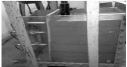
Lal and Mandal (2011)1 studied the behaviour of cellular reinforced retaining walls without and with reinforced backfill through model tests. The schematic of Cellular reinforced wall is shown in Fig. 1.
Figure 1: Cellular Reinforced Wall In Model Test Tank
Available Online at www.ijpret.com 243 water bottles were tied with the help of a plastic wire to form geocell mattresses and geocell strips.
The model test wall was positioned at 120 mm from the front face of the tank in order to accommodate the wall deformations, including the failure deformations during the collapse stage. A load cell having capacity of 50kN was used for measuring vertical load. LVDTs were used for measuring the horizontal deformation. The backfill is reinforced with geocell reinforcement with spacing of 100 mm and length equal to 0.7H, where ‘H’ is height of facing panel. The load was applied through a load cell which was placed centrally on a rigid steel plate of 10mm thickness.
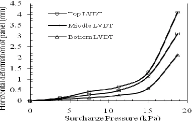
In unreinforced case the backfill was collapsed as soon as surcharge load is applied. For a particular surcharge value the horizontal panel displacement is less in case of geocell mattress reinforced backfill compared to geocell strip reinforced backfill. Figure 2(a) and (b) shows horizontal displacements of panel at various surcharge pressures.
Figure 2(a): Horizontal Displacements of Panel at Various Surcharge Pressures for Geocell Mattress
Available Online at www.ijpret.com 244 Major conclusions drawn from their study are given as:
i. The failure load of geocell mattress reinforced wall is greater compared to geocell strip reinforced wall.
ii. For a particular surcharge value, geocell mattress reinforced wall shows reduced panel displacement as compare to geocell strip reinforced wall.
iii. Results shows better performance of geocell mattress reinforced wall over the geocell strip reinforced wall.
Lal and Mandal (2012)2 carried out laboratory model experiments on cellular reinforced fly ash retaining wall under uniformly distributed surcharge load. The behaviour of cellular reinforced fly ash wall experiments was carried out in a steel tank of 0.7 m long, 0.36 m wide and 0.5 m deep. Line sketch of the model test setup are shown in Figure 3.
Figure 3: Line Sketch of Model Setup
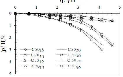
Available Online at www.ijpret.com 245 Figure 4: Normalized Facing Panel Displacements to Normalized Height of the Panel for
Unreinforced Case
The settlement (ρ) of the back fill under uniformly distributed load increments was measured at two number of location by two LVDTs placed at top of the back fill. Figure 5 shows the graph between normalized surcharge pressures to normalized settlement of the back fill.
Figure 5: Relationship between Normalized Surcharge Pressures to Settlement of Back Fill
Based on the result of research work they were concluded the following-
i. The tests results of cellular reinforced fly ash retaining walls subjected to uniformly distribute loading conditions indicate that, for all the cases of cellular reinforced fly ash retaining walls, the observed failure load is greater than the unreinforced case.
Available Online at www.ijpret.com 246 iii. For all the cases of reinforcement, the back fill settles more near to facing element than at
far from facing element.
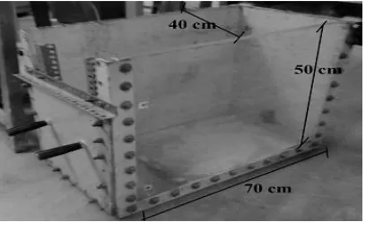
Bhardwaj and Mandal [2008]3 performed the Centrifuge tests on fly ash without and with fiber reinforcement at slope angle, θ = 78.6°. Figure 6 shows the dimensions of the slope model used in the test. Front and back sides of the container were covered with glass plates and Remaining portion was covered using geofoam pieces. To minimize the friction in between the soil and geofoam, plastic sheets were used, after applying silicon grease. All three potentiometers were adjusted in such a manner that their locations were 2.5 cm, 4.0 cm and 5.5 cm respectively from the back face of sample. No surcharge was used in this case; the sample was allowed to fail under self-weight, by increasing the RPM.
Figure 6: Dimensions of the Slope Model Used in Centrifuge Test, for θ = 78.6°
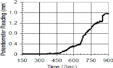
Potentiometers were used in the experiments to measure the vertical displacements of the slope models. Data obtained from the centrifuge test, shows that polypropylene fiber reinforced slope achieves the angular velocity equal to that of unreinforced soil i.e. 440 rpm. And finally polypropylene fiber reinforced slope failed at 722 rpm. Scale factor of polypropylene fiber reinforced slope at 722 rpm was 134. Variation of potentiometer reading with time is shown in Figure 7.
Available Online at www.ijpret.com 247 Figure 7: (b) Variation of Potentiometer Reading with Time for Reinforced Case
Based on the results obtained from their study, the following conclusions were made:
i. It was observed from the centrifuge test that scale factor for reinforced slope increases as compared to unreinforced slope. Polypropylene fiber reinforcement reduces the vertical displacements.
ii. It can be concluded that in case of reinforced slopes displacements are less as compared to unreinforced slopes.
iii. Due to fiber reinforcement, the values of factor of safety obtained from finite element analysis show the similar trend of increase as in case of Bishop’s Method.
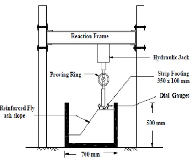
Mandal and Adhana [2011]4 conducted the model tests in the laboratory without and with reinforcement in fly ash slopes on soft foundation to check the stability of steep slope. Fly ash was used as fill material and circular geocell strip and geogrid strip were used as reinforcement. The model test set up is shown in figure 8.
Figure 8 : Model Test Set Up
Available Online at www.ijpret.com 248 incremental load is applied through hydraulic jack on the plate of size 350 mm x 100 mm placed at the distance of 50 mm from the edge of the slope. Two LVDT’s are placed on the slope face to measure the lateral deformation of the slope and two LVDT’s are placed on the top of plate to measure the vertical deformation of the slope.
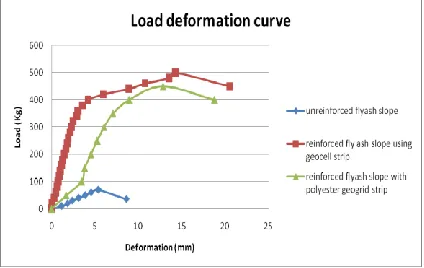
The test was conducted on unreinforced slope, reinforced slope with circular geocell strip and with geogrid strip. Load deformation curve for three different cases are shown in Figure 9.
Figure 9 : Load - Deformation Curve for 3 Different Cases
Based on the result of research work they were concluded the following-
i. The circular geocell reinforcement develop significant amount of confinement and or hoop stresses.
ii. The geocell strip is more efficient than that of geogrid strip.
iii. The factor of safety satisfies the design of steep circular geocell reinforced soil slope.
MATERIALS AND TEST MODEL
Plastic Waste
Available Online at www.ijpret.com 249 Figure 10: Waste Plastic Bottle Chips
Properties of Plastic Waste
Plastic water bottle wastes in the form of chips were used as reinforcing material. Polyethylene terephthalate (PET) is the polymer used in the manufacture of plastic bottles. The melting point varies from 473 °F to 500 °F (245 °C to 260 °C). PET is incompatible with strong oxidizing agents and strongly alkaline materials. Specific gravity and tensile load is 1.33 and 350N respectively.
Rubber Tyre Shreds
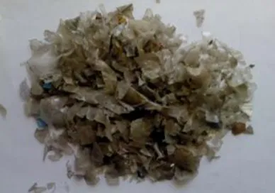
Shredded tyre material was obtained from the waste generated from tyre re-threading industries at MIDC Amravati. The shredded Tyre material used is of size 10mm to 25 mm in length. The shreds have a thickness ranging from 2 to 3 mm and they don’t contain any steel wire or nylon fibers. Specific gravity of tyre shreds obtained with a pycnometer test ranges from 0.90 to 1.12. Above data collected from research paper. The rubber tyre shreds, which are used in project work is shown in Figure 11.
Figure 11: Rubber Tyre Shreds
Available Online at www.ijpret.com 250 Fly Ash
The fly ash used, in these investigations is obtained from Indiabulls power limited, Nandgaon Peth MIDC, Amravati. The properties of fly ash were determined by standard test procedures and tabulated as per provision of IS codes of practice fly ash used for the project is shown in
Figure 12.
Figure 12: Test Fly Ash
Test Model
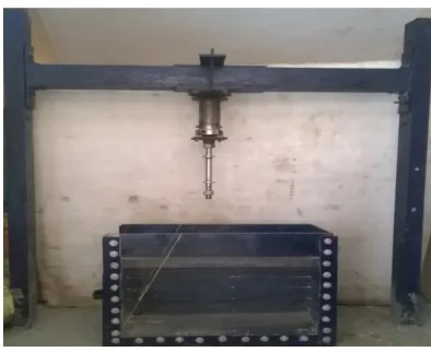
The test model used for experimental investigation was fabricated at GCOEA campus. Figure 13 shows the loading arrangement for model test set up.
Figure 13: Loading Arrangement for Project Work
Methodology
Available Online at www.ijpret.com 251 content and dry density at which the plastic waste chips and rubber tyre shreds to be mixed with fly ash. The Unconsolidated undrained direct shear test were conducted to determine the cohesion and shearing resistance of fly ash so as to determine safe slope angle for constructing fly ash steep slope.
In this study, Fly ash steep slope will be constructed in the model test tank. Primarily the unreinforced fly ash slope will be constructed at steep slope angle, the loading is applied through screw jack and its horizontal as well as lateral deformation will be measured with the help of dial gauges. In reinforced case the waste plastic chips and rubber tyre shreds will be added to the fly ash from 1 to 5% individually and the slope stability test will be carried out. The failure pattern of fly ash slope will be observed through the Perspex sheet fixed on the front side of test tank. The actual model set up is shown in Figure 14. The load settlement curve for the above cases will be plotted and optimum load carrying capacity will be decided and also the factor of safety for the same will be calculated.
Figure 14: Test Model Set Up
TEST RESULTS AND DISCUSSION The results of various tests carried out during the
experimental investigation have been presented in this section.
Properties of Fly Ash
Available Online at www.ijpret.com 252 Table 1: Properties of Fly ash
Sr. No Properties Values
1 Specific gravity 2.05
2 Liquid limit 23.6
3 Plastic limit NP
4 Maximum dry density
( kN/m3 )
10.6
5 Optimum moisture content (%) 26.2
6 Cohesion (kN/m2) 1
7 Angle of Internal Friction (Ø) 33o
Proctor Test Results
The maximum dry densities and optimum moisture contents of the fly ash with different percentage of Waste plastic chips and rubber tyre shreds contents are reported in the Table 2 and Table 3. The results from proctor test shows that the dry density in case of rubber tyre shreds mixed with fly ash is increased upto 3% after which it decreases and in case of plastic waste chips mixed with fly ash shows little increase in dry density for 2% beyond which there is no significant effect on density. The maximum dry density verses optimum moisture content for two different reinforcement is shown in Figure 14 and Figure 15 respectively.
Table 2: MDD & OMC of Soil at Varying Rubber Tyre Shreds Content
Rubber Tyre Chips (%)
OMC (%)
MDD (KN/m3)
0 26.20 10.60
1 25.20 10.72
2 26.90 11.25
3 25.50 11.91
4 25.60 11.74
Available Online at www.ijpret.com 253 Figure 15: MDD & OMC of Soil at Varying Rubber Tyre Shreds Content
Table 3: MDD & OMC of Soil at Varying Plastic Chips Content
Plastic Content (%)
OMC (%)
MDD (KN/m3)
0 26.20 10.6
1 23.6 10.79
2 23.5 11.16
3 24.9 10.98
4 24.0 11.07
5 23.25 11.01
Available Online at www.ijpret.com 254 CONCLUSIONS
Based on the experimental investigations following are some of the conclusions obtained by various research work.
i.The load carrying capacity of geocell mattress reinforced wall is greater compared to geocell strip reinforced wall.
ii.Cellular reinforced fly ash retaining walls subjected to uniformly distribute loading conditions indicate that, for all the cases of cellular reinforced fly ash retaining walls, the observed failure load is greater than the unreinforced case.
iv. The centrifuge test conducted on fly ash slope reinforced with Polypropylene fiber reduces the vertical displacements.
v. The factor of safety satisfies the design of steep circular geocell reinforced soil slope.
The present study has shown results and following important conclusion can be drawn from the study.
i. Maximum dry density of fly ash mixed with rubber tyre shreds increases upto certain percent beyond which it remains constant.
ii. Dry density of fly ash mixed with waste plastic chips increases with 2% of fly ash further inclusion of plastic chips upto 5% does not show any significant effect on density.
iii. It is expected from the experimental work that the load carrying capacity of fly ash slope reinforced with rubber tyre shreds and plastic waste should increased.
iv. The factor of safety for reinforced case required to be increased than that from unreinforced case.
REFERENCES
1. Lal B.R. and Mandal J.N., ‘‘Cellular Reinforced Fly Ash Retaining Wall - Experimental and Finite Element Analysis’’, Proceedings of Indian Geotechnical Conference Kochi, Paper No. K384, December 15-17, 2011.
Available Online at www.ijpret.com 255 3. Bhardwaj D.K. and Mandal J.N.,‘‘Study on polypropylene fibre reinforced fly ash slopes’’, The 12th International Conference of International Association for Computer Methods and Advances in Geomechanics (IACMAG) , Goa, India, 2008, pp. 3778-3786.
4. Adhana S. and Mandal, J. N., “Reinforced Fly Ash Slope Using Different Geosynthetics",
Proceedings of Indian Geotechnical Conference Kochi, December 15-17, 2011, Paper No. J-194.