Available Online At www.ijpret.com
INTERNATIONAL JOURNAL OF PURE AND
APPLIED RESEARCH IN ENGINEERING AND
TECHNOLOGY
A PATH FOR HORIZING YOUR INNOVATIVE WORK
WIDE AREA MEASUREMENT USING PHASOR MEASUREMENT UNIT
SANDIP P. THAWKAR1, ROHIT G. KANOJIA2, P. M. DEOGHARE2
1. Dept. of Electrical Engg, Y.C.C.E, Nagpur, India.
2. Asst. Professor, Dept. of Electrical Engg, Y.C.C.E, Nagpur, India.
Accepted Date:
27/02/2013
Publish Date:
01/04/2013
Keywords
Synchronized phasor
measurement unit (PMU),
Wide Area Measurement
System (WAMS),
Time synchronization,
GPS system
Corresponding Author Mr. Sandip P. Thawkar
Abstract
This paper presents a new synchronized phasor measurement
unit based measurement scheme for widely spread
transmission line network. The principle of the measurement
scheme depends on comparing voltage magnitude at each bus
during normal condition and fault condition inside a wide area
network system to detect the nearest bus to the fault and
current magnitudes for each interconnected line between two
areas on the network. The new technique depends on
synchronizes phasor measuring technology with high speed
communication system and time transfer GPS system. The
simulation of the interconnected system is applied on 400 KV
Available Online At www.ijpret.com
1 Out1 Re
Im Real-Imag to
Complex
In Me an
In Me an
3 cos
2 sin
1 in I. Introduction
System-wide disturbances in power systems
are a challenging problem for the utility
industry because of the large scale and the
complexity of the power system. When a
major power system disturbance occurs the
protection and control actions are required
to stop the power system degradation,
restore the system to a normal state, and
minimize the impact of the disturbance [1].
The present control actions are not
designed for a fast developing disturbance
and may be too slow. Further, dynamic
simulation software is applicable only for
off-line analysis.The recent enlargement
and increased complexity of power system
configurations has led to adjacent
arrangements of short and long distance
power transmission lines, both connected
to the same busbar in a substation [2].
This causes difficult situations when relay
engineers coordinate reach or operate time
among distance relays to cope with
this, current differential protection which
utilizes wide-area current data would be
effective for wide-area backup protection
although such protection needs
system-wide timing synchronism for the
simultaneous current sampling at all remote
terminals and data exchanges among them.
The proposed technique provide an ideal
measurement system for protection,
monitor and controlling wide power system
networks voltages and currents using
phasor measurement unit. It measures
positive sequence (negative and zero
sequence quantities, if needed) voltage and
currents of a power system in real time with
time synchronization, fast communication
system and GPS.
II. Phasor Measurement Unit (PMU)
The phasor measurement unit (PMU)
provide real time measurement of
synchronised sequence components of
voltage and current in transmission
network. This unit compares accurate
measurement over wide area network. For
the phasor measurement calculation
Available Online At www.ijpret.com
proposed technique, a voltage magnitude
and the current magnitude is used. Fig. 1
shows the phasor measurement unit
It consist of low pass filter(LPF), an
analog-to- digital converter for analog to
digital (A/D)conversion, Discrete fourier
transform(DFT) and Sequence analyzer,
GPS, time synchroniser.
V and I analog Channel
LPF A/D DFT Sequence
analyzer
Synchronized Phasor measurement GPS
Receiver
Time Synchr
Fig.1. Phasor measurement unit block
diagram
The phasor measurement unit represented
by discrete phase sequence analyser block
which convert three phase signal of voltage
or current to a positive negative and zero
sequence component magnitude and angle,
if needed.
Fig. 2. Discrete fourier transform (DFT)
Fig. 2 shows the analog power signal that
converted into digital data by the analog to
digital converter. For example, if the voltage
is needed to be measured, the samples are
taken for each cycle of the waveform and
then the fundamental frequency
component is calculated using (DFT). The
figure also shows a simple block diagram
explaining the procedure of measured
voltage or current analog signal.
The relay decision is based on
collected and shared data through
communication network. The suggested
technique satisfies high degree of reliability
and stability while it is based on shared
decision.
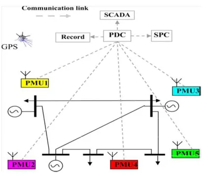
Fig. 3. PMU arrangement at five bus system
Phasor measurement system have been
implemented as real time system
Available Online At www.ijpret.com
units (PMU) installed at substation send
data in real time over dedicated
communication channels to a data
concentrator at a utility control centre . This
approach allow the data to be used in
system protection scheme as well as being
recorded for system analysis and monitored
in SCADA system. PMUs measure the bus
voltage(s) and all the significant line
currents. These measurements are sent to a
Phasor Data Concentrator (PDC) at the
control center. The PDC correlates the data
by time tag to create a system-wide
measurement. The PDC exports these
measurements as a data stream as soon as
they have been received and correlated.
System protection center (SPC) receive
Data stream and make a wide area
protection depending on wide area view.
This principal of operation is used in this
paper.
Studied Network
Three generators are interconnected to
each other, bus 1, bus 2 and bus 3 is of 400
KV simulation studied on same transmission
line. PMU are installed at all bus’s. It
measure and compare real time voltage
magnitude at each bus and current
magnitude at each interconnected line
component data from PMU’s in central unit,
with fast communication , (GPS ) system
and precise time synchronization. In
differential protection fibre optics cable are
used now recently replaced that is into
PMU’s. For the measurement of currents at
both ends of the system by using fibre
optic cables. The main drawback of that
system is measurement very difficult for
very long distance. The application of the
fibre optics is limited.
Transmission line protection is the most
challenging function in power system
protection. Two - third of faults in power
system occurs on the transmission line
network. Disturbances in power system are
changing problem for the utility industry
because of the large scale and complexity of
power system. Earlier in the differential
protection pilot wire are used now we
replace that is into PMU. The solution is
more advanced protection to achieve the
required balanced in transmission line
network.
Available Online At www.ijpret.com
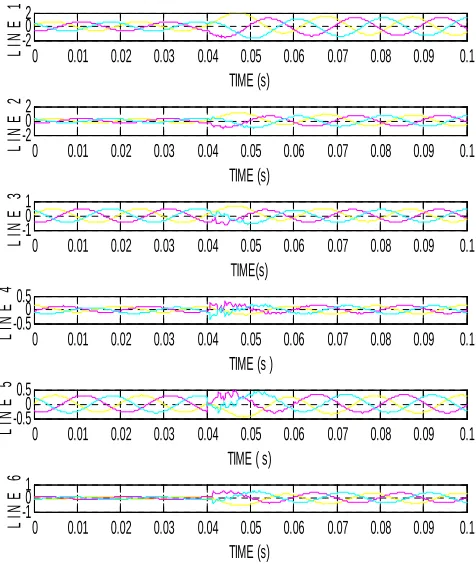
0 0.01 0.02 0.03 0.04 0.05 0.06 0.07 0.08 0.09 0.1
-20 2 TIME (s) L IN E 1
0 0.01 0.02 0.03 0.04 0.05 0.06 0.07 0.08 0.09 0.1
-20 2 TIME (s) L IN E 2
0 0.01 0.02 0.03 0.04 0.05 0.06 0.07 0.08 0.09 0.1
-10 1 TIME(s) L IN E 3
0 0.01 0.02 0.03 0.04 0.05 0.06 0.07 0.08 0.09 0.1
-0.50 0.5
TIME (s )
L
IN
E
4
0 0.01 0.02 0.03 0.04 0.05 0.06 0.07 0.08 0.09 0.1
-0.50 0.5
TIME ( s)
L
IN
E
5
0 0.01 0.02 0.03 0.04 0.05 0.06 0.07 0.08 0.09 0.1
-10 1 TIME (s) L IN E 6
Fig. Voltages magnitudes at different bus’s
Fig. Currents magnitude in line’s
Conclusion
The paper presents a new protection
technique for transmission grids using
phasor synchronized measuring technique
in a wide area system. The protection
scheme has successfully identified the
faulted line all over the interconnect
system. The relay descried in this paper
represents a new state-of-art in the field of
interconnected grid protection for many
reasons. The relay is based on sharing data
from all areas. One relay is used instead of
many stand alone relays with different
complexity coordination. The relay has the
feature of unit protection in identifying the
faulted zone. One and only one trip decision
is issued from the protection center. The
relay has a very fast detection time
estimated by 5 msec for all fault cases. In
the near future and with a very fast
communication links the relay can be
considered as a main relay on the
interconnected grids.
References
1. S.R. Bhide, Paithankar, Power System
Protection, second edition PHI New Delhi,
2010.
2. W.D. Stevenson, Elements of Power
System Analysis, 4th ed., M.G.-Hill Book Co.,
New York, 1988.
3. Hassan K. Zadeh, Zuyi Li, “Phasor
measurement unit based transmission line
protection scheme design. Electrical Power
Systems Research81(2011),pp.421-429.
4. M.M. Eissa, M. ElshahatMasoud, M. M.
Available Online At www.ijpret.com
Area Protection Technique for Power
Transmission Grids Using Phasor
Measurement Unit” IEEE trans.
VOL.25,NO.1 Jan-2010.
5. F. Namdari, S. Jamali, P. A. Crossley,
“Power differential based wide area
protection” Electrical Power System
Research 77(2007) 1541-1551.
6. F. Namdari, S. Jamali, P.A. Crossley,
Differential protection of transmission lines
using real power signals, in: Proceedings of
the International Conference on Advanced
Power System Automation and Protection,
South Korea, 2004, pp. 25–28.
7. U. Serizawa, M. Myoujin, K. Kitamura,
and N. Sugaya, “Wide area current
differential backup protection employing
broadband communication and time
transfer systems,” IEEE Trans. Power Del.,
vol. 13, no. 4, pp. 427–433, Oct. 1998.
8. C.-S. Chen, C.-W.Liu, and J.-A. Jiang, “A
new adaptive PMU based protection
scheme for transposed/untransposed
parallel transmission lines,” IEEE Trans.
Power Del., vol. 17, no. 2, pp. 395–404, Apr.
2002.
9. Y. Serizawa, et al., “Experimental
examination of wide-area current
differential backup protection employing
broadband communications and time
transfer systems”, in proc. IEEE Conf. Power
Engineering Society Summer Meeting, vol.