Discrimination of Inrush from Fault Currents in Power
Transformers Based on Equivalent Instantaneous Inductance
Technique Coupled with Finite Element Method
M. Jamali*, M. Mirzaie* and S. A. Gholamian*
Abstract: The phenomenon of magnetizing inrush is a transient condition, which occurs
primarily, when a transformer is energized. The magnitude of inrush current may be as high as ten times or more times of transformer rated current that causes malfunction of protection system. So, for safe running of a transformer, it is necessary to distinguish inrush current from fault currents. In this paper, an equivalent instantaneous inductance (EII) technique is used to discriminate inrush current from fault currents. For this purpose, a three-phase power transformer has been simulated in Maxwell software that is based on finite elements. This three-phase power transformer has been used to simulate different conditions. Then, the results have been used as inputs in MATLAB program to implement the equivalent instantaneous inductance technique. The results show that in the case of inrush current, the equivalent instantaneous inductance has a drastic variation, while it is almost constant in the cases of fault conditions.
Keywords: Equivalent Instantaneous Inductance, Finite Element, Inrush Current.
1 Introduction1
Power transformers are a class of very expensive and vital component of electric power systems. The cost associated with unplanned outage of a power transformer is very high. So, it is important to minimize the frequency and duration of unwanted outages in this component. One of the main reasons for wrong operation of protective system for the transformer is inrush current. Inrush current is a transient current that occurs in a transformer due to flux saturation in the core and its magnitude can be as high as fault currents. Because inrush current is not a fault current, it is important to develop a technique to distinguish this current from fault currents. In this regard, some techniques have been proposed in the literature. Since a magnetizing inrush current generally contains a larger second harmonic component, [1] used second harmonic criteria to distinguish inrush current from fault currents. Also, for improving the second harmonic restraint algorithm, in [2] instead of measuring the ratio between the magnitudes of the second and fundamental harmonic
Iranian Journal of Electrical & Electronic Engineering, 2011. Paper first received 23 Nov. 2010 and in revised form30 Apr. 2011. * The Authors are with the Department of Electrical and Computer Engineering, Babol University of Technology, P. O. Box 484, Babol, Iran.
E-mails: [email protected], [email protected] and [email protected].
components, a ratio between the phasors of them has been used. In [3-4], discrimination of inrush current from fault currents have been investigated based on wavelet transform. In this technique, the wavelet transform is implemented on the differential currents and inrush current is distinguished from fault currents based on different features of their wavelet components. Identification of inrush current in transformer using error estimation technique is discussed in [5]. Based on error estimation technique, first, the dead angles are extracted from the differential current waves. Then, with comparing this wave with two reference waves, inrush current can be discriminated from fault currents. In [6], inrush current is discriminated from fault currents by calculating the average of the active power flowing into transformers from each terminal. In [7], by examination of the main flux variation that is constructed by the voltages and currents of transformer windings, inrush current is identified. In [8-9], using S transform, different features are extracted for inrush current and fault currents. For discrimination of inrush current from fault currents, improved correlation algorithm is used in [10]. In this technique, by examination of correlation coefficients between two successive half cycles, inrush current can be distinguished from fault currents.
In this paper, an equivalent instantaneous inductance technique (EII) is used for discrimination of inrush
current from fault currents. First, some formulas based on transformer equivalent circuit have been derived. Then, for verifying these formulas on a typical transformer, a three-phase power transformer has been simulated in Maxwell software together with Simplorer software for investigation of different situations. Finally, a MATLAB program based on derived formulas has been written to check the validity of the formulas.
2 Equivalent Instantaneous Inductance Technique
The differential equation in the primary side of a two-winding transformer can be expressed as follow:
1 m
1 1 1 1
m
di (t) d (t) di (t)
v (t) R i (t) L
dt di (t) dt
λ
= + + ⋅ (1)
where, v1(t), L1, R1 and i1(t) are the terminal voltage, leakage inductance, resistance and current in the primary winding, respectively. Also, λ(t) and im(t) are the flux linkage and magnetizing current, respectively. It should be noted that the voltage drop of the magnetizing branch of transformer core in equation (1) has been considered as follow:
m m
m
di (t)
d (t) d (t)
v (t)
dt di (t) dt
λ λ
= = ⋅ (2)
If Lm is defined as equation (3), then it represents the instantaneous magnetizing inductance of transformer.
m m
d (t) L
di (t)
λ
= (3)
In the normal and internal fault conditions of transformer, the core is not saturated and the magnetizing current is very little. These situations result in constant instantaneous magnetizing inductance that has very small variations. However, the inrush current is result of the transformer core saturation. Because in the inrush situation, the transformer core will alternate between the saturation and normal conditions, the instantaneous magnetizing inductance has vast variations. This situation is shown in Fig. 1 where, Lnorm and Lsat represent the magnetizing inductance in the normal and highly saturated conditions, respectively.
As it can be concluded, the calculation of the instantaneous magnetizing inductance is very difficult, because it depends on the accurate flux linkage in the transformer core. For overcoming this problem, the EII can be defined as a solution. For this purpose, Fig. 2 that shows the general form of the equivalent circuit for a two-winding transformer can be considered. In this model the parameters of the secondary side have been converted to the primary side by the transformation ratio. Also, it should be mentioned that Ls is the leakage inductance in the short-circuit winding, where Ls=∞ corresponds to the normal operation.
Fig. 1Variation of magnetizing inductance during the inrush
current.
Fig. 2General equivalent circuit for two-winding transformer.
For the equivalent circuit shown in the Fig. 2, the following equation can be written in the primary side:
2
1 1 e 1 2 1
di (t) d i(t)
v (t) R i(t) L R i (t) L
dt dt
Δ
= Δ + + + (4)
where Δi(t) and Le are defined as follows:
1 2
i(t) i (t) i (t)
Δ = − (5)
m s
e 1
m s
L L
L L
L L
= +
+ (6)
Le is defined as the EII that is a nonlinear function of Lm with constant L1 and Ls. As it can be concluded, Le will be constant during internal fault and normal conditions, but it will have a drastic variation when an inrush current occurs. Therefore, the EII (Le) has an equivalent characteristic to the instantaneous magnetizing inductance (Lm) and can be used as a criterion for discrimination inrush current from fault currents. The calculation of Le can be done using the parameters of transformer and measured instantaneous currents and voltages of the primary and secondary sides. Because obtaining the accurate values of the transformer parameters is difficult, it is necessary to consider an approximation to simplify the procedure of the calculation of Le. For this purpose, because the voltage drop of the secondary winding load current in L1 and R1 is negligible when comparing with that of the differential current in the R1 and Le, especially for large-scale transformers, the third and fourth term on the right
side of the equation (4) can be eliminated and written as follow:
1 1 e
d i(t) v (t) R i(t) L
dt
Δ
= Δ + (7)
Equation (7) has been transformed into a discrete difference equation form using trapezoid principle. At kT instant, this equation is as follow:
1 1 e
i(k 1) i(k 1)
v (k) R i(k) L
2T
Δ + − Δ −
= Δ + (8)
where, T is the sampling cycle. For eliminating R1 in equation (8), equation (7) has been written at (k-1)T instant and this equation together with equation (8) have been used for calculation of the equivalent instantaneous inductance at kT instant as follow:
e 1 1
L =2T[v (k) i(k 1) v (k 1) i(k)]Δ − − − Δ
[ i(k 1) i(k 1)Δ + Δ − + Δi(k) i(k 2)Δ − −
2 2
i (k) i (k 1)]
Δ − Δ −
(9)
Also, it should be noted that the variation of the EII has been calculated using following equations.
N 2
e e e
i 1
1
L L (i) L
N =
⎡ ⎤
Δ =
∑
⎣ − ⎦ (10)N
e e
i 1
1
L L (i)
N =
=
∑
(11)where, N is the number of samples per power frequency cycle. ΔLe is used to discriminate inrush current from the fault current based on the following criterion: If
e
L
Δ exceeds a threshold, then there is an inrush
current, otherwise fault situation has been occurred.
3 Simulation Results
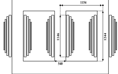
In order to verify the validity of the mentioned method in the discrimination of inrush current from fault currents, a three-phase power transformer has been simulated in Maxwell software that is based on finite element method (FEM). The FEM is a rapid and effective way in simulation and modeling of advanced engineering systems that solve a problem by dividing the problem domain into several elements and then applying physical laws to each small element [11-12]. Also, Simplorer software has been used to create transformer connections and different situations including magnetizing inrush and fault conditions. The parameters of the simulated transformer are given in Table 1.
It should be mentioned that the analysis has been investigated on the lower tap that is including HV1. Fig. 3 shows this three-phase power transformer in the Maxwell environment. Also, some geometry of the
employed transformer with 2D representation is drawn in Fig. 4.
The magnetization curve of transformer core is shown in Fig. 5. This curve has been assigned to the material that is used for modeling the nonlinear nature of transformer core.
It should be noted that a 2 kHz sampling frequency has been used to obtain data from different conditions. Then, the obtained data have been transferred to the MATLAB software. In this software, a program based on equations (9-11) has been written to obtain EII in
Table 1Parameters of the simulated transformer.
Transformer connection Δ/Y (LV/HV)
Rated apparent power 30 MVA
Voltage ratio 20/63 kV
Rated frequency 50 Hz
Number of LV turn (each limb) 232
Number of HV1 turn (each limb) 352
Number of HV2 turn (each limb) 70
Number of HV3 turn (each limb) 63
Core steel type M5
Fig. 3Simulated transformer in Maxwell environment.
Fig. 4 Primitive geometry of the simulated transformer in Table 1 (dimensions are in mm).
Fig. 5 Magnetization curve of the modeled transformer.
different cases. The following sections present the results of the above mentioned procedure.
3.1 Magnetizing Inrush Situation
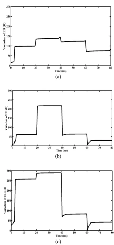
In this case, the inrush phenomenon is created through the connection of no load power transformer to the power source in zero time. The inrush amplitude in this situation for the three-phase power transformer is shown in Fig. 6. As seen from the figure, all phases have shown inrush current situation that should be analyzed with EII criterion.
Figure 7 shows the variation of the EII for three phases of transformer. As seen from the figure, EII for all phases show a drastic variation with high amplitude, which is the key feature of the inrush current.
3.2 Internal Short Circuit Fault
For the simulation of internal fault, two cases have been considered. The first one is the turn-turn short circuit and the second is the turn-ground short circuit.
3.2.1 Turn-Turn Short Circuit
In this case, a short circuit of 30 turns in the phase C for the on load situation of transformer has been considered. Fig. 8 shows the differential currents of all phases in this situation.
Fig. 6Inrush current for all three phases.
(a)
(b)
(c)
Fig. 7Variation of EII in the case of inrush current (a) phase
A (b) phase B (c) phase C.
Fig. 8Differential currents when the short circuit of 30 turns
occurs in the phase C.
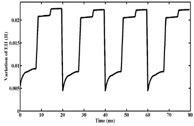
As seen from Fig. 8, the differential currents of A and B phases are within the range of nominal magnetizing current, but C phase current is larger than the nominal magnetizing current. Therefore, it is necessary to calculate EII for C phase. As seen from the Fig. 9, the calculated EII for C phase shows a small variation which corresponds to the mentioned criterion.
3.2.2 Turn-Ground Short Circuit
In this case, a turn-ground short circuit in phase B has been considered. Fig. 10 shows the differential currents of all phases in this situation. As seen from Fig. 10, the differential current of B phase is larger than the nominal magnetizing current, while the differential currents of other phases are in normal range. Therefore, it is necessary to verify B phase with the mentioned method.
Figure 11 shows the calculated EII for B. As it can be concluded from this figure, a small variation in EII of B phase corresponds to the mentioned criterion for fault situations. So, similar to previous case, the fault situation can be characterized with small variation in EII.
3.3 Single Line to Ground Fault
In this case, a single line to ground (phase A) occurred on the secondary side with a balanced Y connected of phase connected to the secondary side.
Figure 12 shows the three differential currents. In this situation, the differential current of phase A is larger than the nominal. Therefore, the phase A must be analyzed with EII criterion. Fig. 13 shows the calculated EII for phase A. As seen in this figure, from the small variation of EII, it can be concluded that the fault situation has been occurred and the relay must operate.
As it can be concluded from the EII figures for different situations including inrush and fault conditions, the variation of EII for fault situations are very small (at most 0.02), while it is high for inrush situation (at least 50), so a safe threshold between these two numbers can be selected for discrimination purpose.
Fig. 9 Variation of EII of phase C in the case of turn-turn
short circuit.
Fig. 10 Differential currents in the case of turn-ground short
circuit in the phase B.
Fig. 11 Variation of EII of phase B in the case of turn-ground
short circuit.
Fig. 12 Differential currents in the case of single line to
ground fault in phase A.
Fig. 13Variation of EII of phase A in the case of single line to
ground fault.
4 Conclusi
In this pa (EII) techniq current from different beh current and inrush curren constant dur validity of t inrush curren transformer that is based data of diffe EII techniqu the techniqu from fault cu
References [1] Sykes method protect IEEE PAS-9 [2] Kaszte transfo securit perform Protec
[3] Faiz J. algorit from transfo No. 4, [4] Youss discrim inrush Power 2003. [5] He B., identif IEEE 1163-1 [6] Yabe discrim inrush Power 1997. [7] Zhao magne transfo Sixth Machi 320, N [8] Jiao S
to ide transfo
Electri
Oct. 20
ion
aper, an equiva que has been m fault curren haviors of th fault current nt has a drasti ring fault co the EII techn nt from fault has been sim d on finite el erent situation e. The results ue in the disc urrents.
J. A. and M d of harm ting of transf
Trans. Power
91, pp. 1266-1 enny B. and ormer inrush ty while m mance”, 53r ctive Relay En
. and Lotfi-Fa thm for disc magnetizing ormers”, IEEE
pp. 1989-199 ef O. A. S., “A mination betw
currents in
r Del., Vol.
, Zhang X. an fy inrush curre
Trans. Powe
1168, July 200 K., “Powe mination betw
current in
r Del., Vol. 1
X., Chai J. a etizing inru ormers based
International ines and Syst
Nov. 2003. ., Wang S. an entify curren orm”, Inter ical Machines
008.
alent instantan n used to dis nts. This meth
he calculated ts. The calcu ic variation, w onditions. Fo
ique in the d currents, a th mulated in M lement metho ns have been s show a good crimination o
Morrison I. F monic restra
formers by di
r Apparatus a
272, May 197 Kulidjian A.
restraint alg maintaining
rd Annual ngineers, pp. 1
ard S., “A nove crimination o
inrush curr
E Trans. Pow
96, Oct. 2006. A wavelet-bas ween faults a transformers 18, No. 1, pp
d Bo Z. Q., “A ent based on e
er Del., Vol.
06.
er differentia ween fault a transformers 2, No. 3, pp.
and Su P., “ ush current d on features
l Conference tems, Vol. 1,
nd Zheng G., “ nt based on
rnational C s and Systems
neous inducta scriminate inr hod is based d EII for inr
lated EII dur while it is alm or checking discrimination hree phase pow Maxwell softw
od. The obtai implemented d performance of inrush curr
F., “A propo aint differen igital comput
and Systems, V
72.
., “An impro orithm increa
fault respo
Conference
1-27, Apr. 200 el Wavelet-ba f internal fa rents in pow
wer Del., Vol.
sed technique and magnetiz s,” IEEE Tra
p. 170-176, J
A new method error estimatio
21, No. 3,
al method and magnetiz ”, IEEE Tra
1109-1118, J
“Identification ts of pow
of flux locu
e on Electr
No. 1, pp. 3
“A new appro generalized
Conference s, pp. 4317-43
ance rush on rush ring most the n of wer ware ned d on e of rent osed ntial ter”, Vol. ved ases onse for 00. ased aults wer 21, e for zing ans. Jan. d to on”, pp. for zing ans. July n of wer us”, ical 317-oach S-on 322, [9] [10 [11 [12 elem ele eng Sci inc inte tran 200 eng Teh the Un pow of e
] Zhang Q.
inrush cur based on
Conferenc Applicatio
0] Ling X., identificat correlation Vol. 17, N 1] Liu G. R
method: A
Ltd., 2003 2] Faghihi F for the m using aux for evalua
of Electri
No. 1, pp.
ment modelin ctromagnetic f gineering.
ience and Tec lude high volt ernal faults a nsformers, cabl
01. He also gineering from hran, Iran in 20 e department niversity of Tec wer electronic a electrical mach
., Jiao S. and rrent and inte n hyperbolic
ce on Indu ons, pp. 258-2
Liu P. and M tion of the in n algorithm” No. 4, pp. 901-R. and Quek
A practical
3.
F. and Heydar minimized str iliary winding ation of FEM
ical & Electr
. 62-69, Mar. 2
Morteza
Mahmoodab received the electrical en Tabriz, Ta University o Iran in 201 interests application ng, and comp fields, electric
Mohammad
GhaemShah B.Sc and M Engineering Chamran, University Tehran, Ir respectively Engineering chnology in 2 tage engineerin and studying les, generators,
Sayyed Asg
Babolsar, I B.Sc. degre from K.N Technology M.Sc. deg engineering university o received the m K.N.Toosi
008. He is curre of Electrical hnology, Iran. and design, sim
ines.
d Wang S., “ ernal faults o S-transform”
ustrial Elec
263, May 2009 Malik O. P., nrush based , IEEE Trans
-907, Oct. 200 S. S., The f course, Else
ri H., “Mathem ray fields in gs based on st
results” , Ira ronic Enginee
2010.
Jamali wa
bad, Iran, in e B.Sc. and M ngineering from abriz, Iran i
of Mazandaran 1, respectively include mo of power transf puter aided c machinery and
d Mirzaie w hr, Iran in 1975
M.Sc Degrees g from Univer Ahvaz, Iran of Science an ran in 1997 y and PhD Degr g from Iran 2007. His rese ng, intelligence of insulation insulators, elec
ghar Gholamia
Iran, in 1976. ee in electrica
N.Toosi Un , Tehran, Iran gree in ele
(electrical m of Mazandaran, Ph.D degree University of ently an assista Engineering His research in mulation, model
“Identification f transformer ”, 4th IEEE ctronics and
9.
“Studies for on improved
. Power Del.,
02. finite element evier Science matical proof transformers tate equations anian Journal ering, Vol. 6,
as born in n 1984. He .Sc. degrees in m University of n 2007 and n, Mazandaran, y. His research odeling and formers, finite-calculation of d high voltage
was born in 5. He Obtained s in Electrical rsity of Shahid n and Iran d Technology, 7 and 2000 ree in Electrical University of earch interests e networks for n systems in ctrical motors.
an was born in
He received al engineering niversity of n in 1999 and ectric power machines) from Babol, Iran in in electrical f Technology, ant professor in at the Babol nterests include ing and control
n r E d r d t e f s s l , n e n f d , h d -f e n d l d n , 0 l f s r n n d g f d r m n l , n l e l