© Shiraz University
A Comparative Study on the Formability Prediction
of two-layer metallic Sheets
H. Deilami Azodi
*and R. Darabi
Department of Mechanical Engineering, Arak University of Technology, P.O.Box 38135-1177, Arak, Iran
Abstract: Two-layer metallic sheets have wide applications in aerospace, marine, automotive and domestic industries due to their superlative characteristics. In this paper, the formability of two-layer sheet is investigated through analytical, experimental and numerical approaches. An analytical model is developed based on Marciniak-Kuczynski method associated Hill’s non-quadratic yield criterion. Forming limit diagrams are also obtained numerically based on finite element method using Bifurcation theory and ductile fracture criteria. Furthermore, experiments are carried out on Al3105-St14 two-layer sheet. Theoretical results from various methods are compared with results obtained from experiments to evaluate the competency of discussed analytical and numerical methods to predict the formability of two-layer sheets. The results show that analytical and numerical approaches discussed in this paper have good capabilities to predict the formability of two-layer sheets. However, the analytical method based on M-K model and numerical approach based on bifurcation theory are more suitable to determine the forming limit diagram of Al3105-St14 two-layer sheets.
Keywords: Forming Limit Diagram (FLD), Two-layer Sheet, Marciniak-Kuczynski (M-K) Method, Hill’s Non-quadratic Yield Criterion, Bifurcation Theory, Ductile Fracture.
1. Introduction
As a considerable light-weight and high-strength material, two-layer sheets have generated an increasing attention. Two-layer sheets are gaining a wide array of applications due to the advantageous features in comparison with layers which compose them. Formability of sheet metal is constrained by plastic instability and localized necking. Forming limit diagram (FLD) is a commonly used tool to evaluate the formability of sheets. Initially, the definition of forming limit diagram (FLD) was presented by Keeler [1] and Goodwin [2].
Semiatin and Piehler [3, 4] investigated the formability of stainless steel-clad aluminum and aluminum-clad stainless steel sheets based on defuse and localized necking. They concluded that arrangement of layers is the main factor in localization and fracture. Mori and Kurimoto [5] utilized deep drawing process with a cylindrical punch and stretch forming test with a hemispherical punch to investigate the formability of stainless steel-aluminum clad sheet, experimentally. They concluded that a higher formability can be achieved when the aluminum is set on the outer side of the cup in stretching and deep drawing tests. Yoshida and Hino [6] determined the forming limits of sheet metal laminates under biaxial stress conditions in 1997. A criterion was derived for the left hand side of the FLD based on Hill’s localized necking theory. For determination of the forming limits on the right hand side of the FLD, the M-K theory was used. Furthermore, on two- and three-ply stainless steel-clad aluminum sheets, punch-stretching tests were done. Jalali et al. [7, 8] investigated the formability of Al1100-St12 two-layer sheet analytically and experimentally. They showed that the FLD of two-layer sheet lies between those of elements which compose it. They also studied the influences of material parameters on formability of two-layer metallic sheet.
In this work, the formability of Al3105-St14 two-layer sheet is studied through analytical, experimental and numerical approaches. An analytical model is presented based on Marciniak-Kuczynski method using Hill’s non-quadratic yield criterion. Forming limit diagrams are also obtained numerically based on finite element method using Bifurcation theory and ductile fracture criteria. Analytical and numerical results are compared with experimental ones to examine the validity of theoretical approaches.
2. Theoretical Analysis
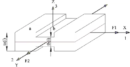
The Marciniak - Kuczynski [9] (M-K) forming limit model is extended in order to predict localized necking in sheet metal forming. Main assumption in this theory is considering a local heterogeneity in the sheet which is an initial imperfection in the form of a groove related to surface roughness [10] perpendicular to greater principal stress direction. Thus, there are two homogenous and inhomogeneous regions that are nominated as “a” and “b”, respectively. As shown in Fig. 1, this groove is assumed to be perpendicular to maximum principal stress on material surface. The plane stress condition is considered. The sheet is stretched under biaxial tension by principal stresses σ1 and σ2. The rolling directions of layers are coincident and assumed as principle direction.
The imperfection factor 𝑓 is determined as the thickness ratio:
𝑓 =∑ 𝑡
𝑏(𝑖)
∑ 𝑡𝑎(𝑖) (1)
In which 𝑡𝑎(𝑖) and 𝑡𝑏(𝑖) are the thicknesses of homogenous and heterogeneous regions of layers, respectively. During the forming process, thicknesses of each layer in the homogenous and heterogeneous regions change in comparison with initial ones. The thickness of the homogenous region is:
𝑡𝑎(𝑖) = 𝑡0𝑎(𝑖). 𝑒𝑥𝑝(𝜀3𝑎(𝑖)) (2)
In which 𝑡0𝑎(𝑖) and 𝑡𝑎(𝑖) are initial and current thickness of 𝑖𝑡ℎ layer in homogenous region, respectively and 𝜀3𝑎(𝑖) is the thickness strain.
Considering the initial value of the coefficient of heterogeneity is described by initial surface roughness and grain size [10, 11, 12], the imperfection factor can be expressed as:
𝑓 =𝑡0
𝑎(𝑖)
− 2(𝑅𝐺(𝑖)+ 𝑘(𝑖)𝑑0(𝑖)𝜀̅𝑏(𝑖))
𝑡0𝑎(𝑖) 𝑒𝑥𝑝 (𝜀3
𝑏(𝑖)
− 𝜀3𝑎(𝑖)) (3)
Where 𝑅𝐺(𝑖) is the initial surface roughness, 𝑘(𝑖) is the coefficient of grain size, 𝑑0(𝑖)is the grain size, 𝜀̅𝑏(𝑖)
is the effective strain in the heterogeneous region, 𝜀3𝑎(𝑖)and 𝜀3𝑏(𝑖) are the thickness strains of the homogeneous and heterogeneous regions for layer i, respectively.
Hill’s non-quadratic yield criterion [13] is expressed as:
𝑗|𝜎2− 𝜎1|𝑀+ 𝑔|𝜎3− 𝜎1|𝑀+ ℎ|𝜎1− 𝜎2|𝑀+ 𝑝|2𝜎1− 𝜎2− 𝜎3|𝑀+ 𝑞|2𝜎2− 𝜎1− 𝜎3|𝑀
+ 𝑙|2𝜎3− 𝜎1− 𝜎2|𝑀= 𝜎̅𝑀
(4)
In which the exponent M depends on material. j, g, h, p, q and l are anisotropy parameters. The yield function, under the plane stress condition and in-plane isotropy, is written as follows:
Fig. 1. Model of localized necking for two-layer sheet.
The stress ratio (𝛼) and strain ratio (𝜌) are defined as:
𝜌 = 𝑑𝜀2 𝑑𝜀1
(6)
𝛼 = 𝜎2
𝜎1 (7)
The associated flow rule is taken to be:
𝑑𝜀𝑖𝑗 = 𝑑𝜆
𝜕𝑄
𝜕𝜎𝑖𝑗 (8)
where 𝑑λ is the proportionality factor and 𝑄 is the plastic potential defined by the yield function. Flow rule associated with Hill’s yield criterion can be written as:
𝑑𝜀1
|𝜎1+ 𝜎2|𝑀−1+ (1 + 2𝑟)|𝜎1− 𝜎2|𝑀−1
= 𝑑𝜀2
|𝜎1+ 𝜎2|𝑀−1− (1 + 2𝑟)|𝜎1− 𝜎2|𝑀−1
= −𝑑𝜀3
2|𝜎1+ 𝜎2|𝑀−1
= 𝑑𝜀̅
2(1 + 𝑟)𝜎̅𝑀−1
(9)
Accordingly
𝜌 =|1 + 𝛼|
𝑀−1− (1 + 2𝑟)|1 − 𝛼|𝑀−1
|1 + 𝛼|𝑀−1+ (1 + 2𝑟)|1 − 𝛼|𝑀−1 (10)
According to equilibrium condition, the forces acting on the homogenous and heterogeneous regions are equal:
∑ 𝐹1𝑎(𝑖)
2
𝑖=1
= ∑ 𝐹1𝑏(𝑖)
2
𝑖=1
(11)
In which 𝐹1𝑎(𝑖) and 𝐹1𝑏(𝑖)are forces applied on direction 1 in regions “a” and “b” for 𝑖𝑡ℎ layer.
Considering isotropic work hardening and strain rate hardening, the behavior of the material for each layer can be expressed as:
𝜎̅(𝑖)= 𝐶(𝑖)(𝜀̅(𝑖))𝑛(𝑖)(𝜀̅̇(𝑖))𝑚(𝑖) (12)
Where 𝐶(𝑖) is the strength coefficient, 𝑛(𝑖) is strain hardening exponent and 𝑚(𝑖) is strain sensitivity coefficient for 𝑖𝑡ℎ layer.
By defining the dimensionless parameter 𝜑 as:
𝜑 =𝜎1 𝜎̅ =
2(1 + 𝑟)
|1 + 𝛼|𝑀+ (1 + 2𝑟)|1 − 𝛼|𝑀 (13)
∑ 𝜑𝑎(𝑖)(𝜀̅𝑎(𝑖))𝑛(𝑖)(𝜀̅̇𝑎(𝑖))𝑚(𝑖). 𝑡𝑎(𝑖)= 2 𝑖=1 ∑ 𝜑𝑏(𝑖)(𝜀̅𝑏(𝑖))𝑛(𝑖)(𝜀̅̇𝑏(𝑖))𝑚(𝑖). 𝑡𝑏(𝑖) 2 𝑖=1 (14)
The Compatibility requirement between the regions “a” and “b” yields to equality of strains at direction 2 of two regions for each layer:
𝑑𝜀2𝑏(𝑖)= 𝑑𝜀2𝑎(𝑖) (15)
Combining equations (5), (9), (13) and (15) gives the effective strain increment in the heterogeneous region as:
𝑑𝜀̅𝑏= 2(1 + 𝑟)𝑑𝜀2
𝑎
|1 + 𝛼𝑏|(𝑀−1)− (1 + 2𝑟)|1 − 𝛼𝑏|(𝑀−1)[
|1 + 𝛼𝑏|𝑀+ (1 + 2𝑟)|1 − 𝛼𝑏|𝑀
2(1 + 𝑟) ]
(𝑀−1) 𝑀 ⁄
(16)
The relation between effective strain increment and principal strain increments is as follows [14, 15]:
𝑑𝜀̅ =[2(1 + 𝑟)]
1 𝑀 ⁄
2 [
1
(1 + 2𝑟)1⁄(𝑀−1)
|𝑑𝜀1− 𝑑𝜀2| 𝑀
(𝑀−1) ⁄
+ |𝑑𝜀1+ 𝑑𝜀2| 𝑀 (𝑀−1) ⁄ ] (𝑀−1) 𝑀 ⁄ (17)
The ratio of effective strain increment to strain increment in direction 1 can be obtained as:
𝛽 = 𝑑𝜀̅ 𝑑𝜀1
=[2(1 + 𝑟)]
1 𝑀 ⁄
2 [
1
(1 + 2𝑟)1⁄(𝑀−1)
|1 − 𝜌|𝑀⁄(𝑀−1)+ |1 + 𝜌|𝑀⁄(𝑀−1)] (𝑀−1)
𝑀 ⁄
(18)
The limit strains are determined by solving above mentioned equations numerically, using following algorithm:
1) Considering a loading path, a finite increment of principal strain (𝑑𝜀1) is imposed on the homogenous regions for two layers. α,𝛽,𝜑, other principal strain increments (𝑑𝜀2, 𝑑𝜀3), effective strain increment (𝑑𝜀̅) and effective stress (𝜎̅) of mentioned region are calculated for each layer using equations (9), (10), (13) and (18).
2) Regarding no slippery condition between layers throughout forming process (𝜌𝑙𝑎𝑦𝑒𝑟1= 𝜌𝑙𝑎𝑦𝑒𝑟2), based on equilibrium condition, equations (14), the stress ratios in heterogeneous regions for two layers
(𝛼𝑏(1), 𝛼𝑏(2)) can be calculated.
3) Knowing 𝛼𝑏(1), 𝛼𝑏(2) for two layers, 𝜌,𝛽 and 𝜑 in heterogeneous region can be determined using equations (10), (13) and (18). So, the strain increments and stress components of two layers are obtained in this zone. If the ratio 𝑑𝜀̅𝑏(𝑖)
𝑑𝜀̅𝑎(𝑖) for one of layers becomes greater than 10, the current values of 𝜀2 𝑎(𝑖)
, 𝜀1𝑎(𝑖) can specify a point of FLD.
4) If the above mentioned ratio isn’t greater than 10, the calculation route will be repeated with adding a strain increment 𝑑𝜀1 to the previous amount of strain.
5) Computation will be conducted while 𝜌 is from -0.5 to 1.0.
3. Experimental Procedure
In order to determine the forming limits of two-layer sheets in experimental study, the Hecker out of plane stretching test [16] was used. Two-layer sheets consist of 0.5 mm thickness aluminum Al3105 sheet and 0.5 mm thickness carbon steel St14 sheet were used.
contacted with hemispherical punch. Circular grids of 5 mm diameter were printed on surfaces of the specimens to measure the strains experimentally. The major and minor strains of localized necking region were calculated with geometry of the deformed grids as follow:
𝜀1= 𝑙𝑛𝐷1 𝐷0
(19)
𝜀2= 𝑙𝑛𝐷2 𝐷0
(20)
where 𝜀1 is major strain and 𝜀2 is minor strain. 𝐷0 is initial diameter of grids and 𝐷1 and 𝐷2are major and minor diameters of deformed grids, respectively. Figure 4 shows 75 × 200 mm specimen after forming.
Table 1. Material properties Al3105 and St14 sheets.
Variables Values
Material St14 Al 3105
Thickness, 𝑡 (mm) 0.5 0.5
Young's modulus, 𝐸 (GPa) 210 70
Poisson's ratio 0.3 0.33
Density, (Kg/m3) 7850 2700
Strength coefficient, 𝐶 (MPa) 548.44 302 Strain hardening exponent, 𝑛 0.229 0.103 Strain rate sensitivity exponent, 𝑚 0.01 0.001
Surface Roughness, 𝑅0(𝜇𝑚) 4 1.6
Anisotropy parameter, 𝑟0 1.77 0.2
Anisotropy parameter, 𝑟90 1.95 0.24
Grain size, 𝑑0(𝜇𝑚) 10 20
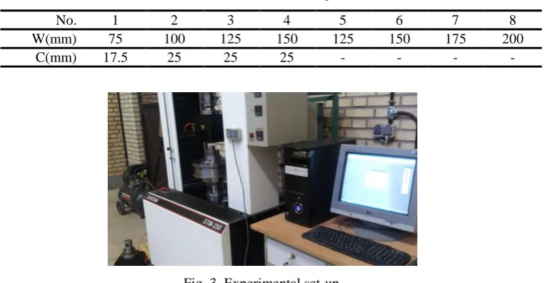
Fig. 2. Schematic of the specimens. Table 2. The dimensions of specimens.
8 7
6 5
4 3
2 1
No.
200 175
150 125
150 125
100 75
W(mm)
- -
- -
25 25
25 17.5
C(mm)
Fig. 4. The 75 mm×200 mm specimen after forming.
4. Numerical Study
In order to do the numerical study of the formability of two-layer metallic sheets, all the consumed geometries in experimental study were simulated using commercially available finite element code ABAQUS/ Standard. In other word, experimental conditions were duplicated in numerical simulation. Punch, die and blank holder were rigid bodies, while two-layer metallic sheets were deformable. Sheets were modeled using four-node shell elements S4R with two integrations. One-quarter of the geometry was modeled due to symmetry condition. A default surface to surface contact explicit used to specify the interfaces between the surfaces of the tooling and the blank. The tie constraint was used between two layers by assuming there is no slipping among layers.
The used surface to surface contact algorithm was automatic to define the interfaces between the surfaces of the tooling and the sheet. This algorithm is based on the penalty method. Coulomb friction model with a constant friction coefficient of 0.1 was used between the sheet-die and sheet-blank holder interface. A friction coefficient of 0.3 was assumed between the blank and the punch. The simulations were performed for 8 specimens given in Fig. 2 to determine the FLD numerically. Figure 5 shows simulated 75mm × 200mm specimen. Two different criteria were employed to predict the onset of failure in numerical study:
Fig. 5. Formed 75 mm × 200 mm Specimen in numerical simulation.
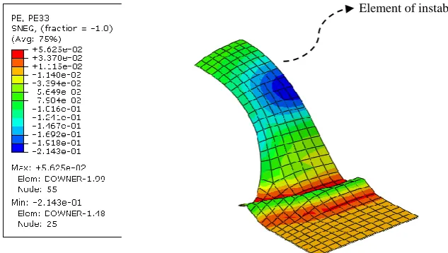
4.1. Bifurcation criterion
Sheet metal formability is often limited by the onset of localized necking. A numerical method to access the forming limit diagram is bifurcation theory. In bifurcation theory [17, 18, 19], onset of necking can be seen
in diagram of second differentiate of thickness with respect to time and the abrupt changing of thickness strain.
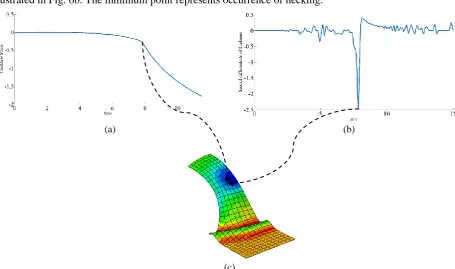
The variation of thickness strain of 75mm×200mm sample with respect to time can be seen in Fig. 6a. The second differentiate of thickness strain respect to time for the 75mm × 200mm specimen is illustrated in Fig. 6b. The minimum point represents occurrence of necking.
(a) (b)
(c)
Fig. 6. (a) Thickness strain and (b) second differentiate of thickness strain versus time for 75 mm × 200 mm Specimen (c) Formed 75 mm × 200 mm Specimen
4.2. Ductile fracture criteria
Deformation history considered in many of ductile fracture criteria affects formability of sheet metals. Thus, ductile fracture criteria can be employed as a potent tool to predict the forming limits of sheet metals. In the following, two ductile fracture criteria used in this work will be explained.
Cockroft and Lathman [20] proposed a criterion considering the role of the largest tensile stress in initiation of fracture. Oh et al. [21] modified the Cockcroft and Latham criterion and suggest a criterion as follows:
∫ 𝜎1
𝜎̅𝑑𝜀̅ = 𝐶1
𝜀𝑓
̅̅̅
0
(21)
where, 𝜎1 is the maximum principal stress, 𝜎̅ is the effective stress and 𝐶1 is material constant.
Brozzo et al. [22] presented a criterion in which the influences of the largest principal stress and the hydrostatic stress on initiation of fracture were considered:
∫ 2𝜎1
3(𝜎1− 𝜎𝑚)
𝑑𝜀̅ = 𝐶2 𝜀𝑓
̅̅̅
0
(22)
In which, 𝜎𝑚 is the hydrostatic stress and 𝐶2 is the material constant.
In order to determine the material constants in Oh and Brozzo ductile fracture criteria, uniaxial tension tests were done for each material. Knowing fracture strain from uniaxial tension test, the material constants for each material were calculated using equations of criteria regarding stress state of uniaxial tension.
Table 3. The calculated material constants 𝐶1and 𝐶2 for Al3105 and St14 sheets C2
C1 Material
0.1 0.12 Al3105
0.26 0.27
St14
5. Result and Discussion
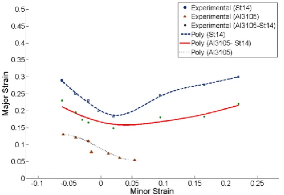
Figure 7 shows the forming limit diagram of Al3105-St14 two-layer sheet compared with those of its components obtained experimentally. It can be seen that FLD of two-layer sheet is located between the FLDs of elements which compose it. Mechanical and geometrical properties of layers determine the exact location of the FLD of the two-layer sheet.
The analytical FLDs of Al3105-St14 two-layer sheet and its components calculated based on M-K method using Hill’s non-quadratic yield criterion are depicted in Fig. 8.
Moreover, Fig. 9 represents numerical FLDs of Al3105-St14 two-layer sheet and separate layers based on Oh and Brozzo ductile fracture criteria.
Analytical, Numerical and experimental results demonstrate that the formability of two-layer sheet is better than the component with lower formability.
Fig. 7. Experimental FLDs of Al3105-St14 two-layer sheet and its components.
(a)
(b)
Fig. 9. Numerical FLDs of Al3105-St14 two-layer sheet and its components based on a) Oh and b) Brozzo ductile fracture criteria.
Forming limit diagram analytically obtained from M-K model associated Hill’s non-quadratic yield criterion, FLDs determined numerically based on Oh and Brozzo ductile fracture criteria, numerically predicted FLD using bifurcation theory and experimental results for Al3105-St14 two-layer sheet are compared and the result is shown in Fig. 10.
It is seen that FLDs calculated from analytical and numerical methods are in a good agreement with experimental results. Hence, it can be concluded that the above-mentioned analytical and numerical approaches have good capabilities to predict the formability of two-layer sheets. However, the FLD obtained analytically by M-K theory and the FLD predicted numerically based on bifurcation theory are more compatible with experiments. It shows that these methods are more suitable to predict forming limits of carbon steel St14 and aluminum alloy Al3105 two-layer sheets.
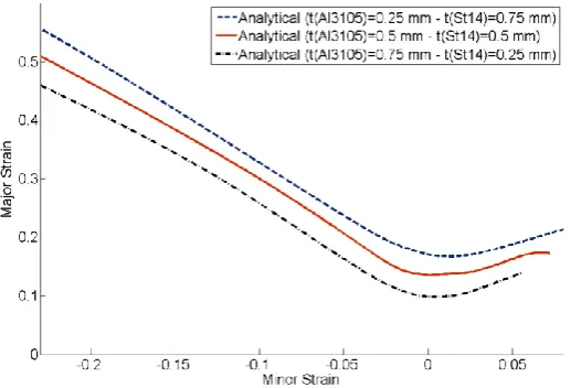
As discussed, the FLD of two-layer sheet is located between the FLDs of separated layers. (Fig. 11) shows that the exact location of the FLD is affected by thickness ratio of layers.
Fig. 10. Comparison between theoretical FLDs determined by various methods and experiments for Al3105-St14 two-layer sheet.
Fig. 11. The effect of the thickness ratio of layers on the FLD of Al3105-St14 two-layer sheet.
6. Conclusion
In this paper, an analytical model was developed to calculate the forming limits of two-layer sheet based on Marciniak-Kuczynski method using Hill’s non-quadratic yield criterion. Bifurcation and ductile fracture criteria are also employed to determine the forming limit diagram of two-layer sheet numerically. Experiments were also carried out on Al3105-St14 two-layer sheet. The validity of the analytical and numerical results was examined by comparison with experimental ones. It can be concluded that:
- The forming limit diagram of two-layer sheet is located between FLDs of separate layers. It means that, the formability of two-layer sheet is better than the formability of layer with lower formability.
- In the case of constancy of total thickness of two-layer sheet, increasing the thickness ratio (tSt⁄tAl) increases the formability.
- The exact location of the FLD of two-layer sheet is influenced by thickness ratio of layers.
7. References
[1] S. P. Keeler, Circular grid system – a valuable aid for evaluating sheet metal formability, SAE Technical Paper, 77 (1968) 371–379.
[2] G. M. Goodwin, Application of strain analysis to sheet metal forming problems in press shop, SAE Transactions, 77 (1968) 380–387.
[3] S. L. Semiatin, H. R. Piehler, Formability of sandwich sheet materials in plane strain compression and rolling,
Metallurgical Transactions A, 10 (1979), 97–107.
[4] S. L. Semiatin, H. R. Piehler, Deformation of sandwich sheet materials in uniaxial tension, Metallurgical Transactions A, 10 (1979) 85–96.
[5] T. Mori, S. Kurimoto, Press-formability of stainless steel and aluminum clad sheet, Journal of Materials Processing Technology, 56 (1996) 242–253.
[6] F. Yoshida, R. Hino, Forming limit of stainless steel-clad aluminum sheets under plane stress condition, Journal of Materials Processing Technology, 63 (1997) 66–71.
[7] -A. Jalali Aghchai, M. Shakeri, B. Mollaei Dariani, Theoretical and experimental formability study of two-layer metallic sheet Al1100/St12, Proceedings of the Institution of Mechanical Engineers, Part B: Journal of Engineering manufacture, 222 (9) (2008) 1131–1138.
[8] -A.Jalali Aghchai, M. Shakeri, B. Mollaei Dariani, Influences of material properties of components on formability of two-layer metallic sheets, International Journal of Advanced Manufacturing Technoloogy, 66 (2012) 809–823. [9] Z. Marciniak, K. Kuczynski, Limit strains in the processes of stretch-forming sheet metal, International Journal
of Mechanical Sciences, 9 (1967) 609–620.
[10]J.Z. Gronostajski, Z. Zimniak, Theoretical simulation of sheet behavior in forming processes, Journal of Materials Processing Technology, 34 (1992) 457–464.
[11]M. Shakeri, A. Sadough, B.M. Dariani, Theoretical and Experimental Analysis of Sheet Metal Formability Limit, Proceedings of the Institution of Mechanical Engineers, Part B: Journal of Engineering manufacture, 214 (2000) 821–827.
[12]-A.Assempour, M. Nurcheshmeh, The influence of material properties on the shape and level of the forming limit diagram, SAE Technical Paper, 01 (2003) 1149.
[13]R. Hill, Theoretical plasticity of textured aggregates, Mathematical Proceedings of the Cambridge Philosophical Society, 85 (1979) 179–620.
[14]M. Pishbin, P.P. Gillis, Forming limit diagrams calculated using Hill’s non-quadratic yield criterion Metallurgical Transactions A, 23 (1992) 1992-2817.
[15]J. Gronostajski, The effect of strain path on the plastic instability, Proceedings of the 3rd International Conference on the Technology of Plasticity, Kyoto, Japan, (1990), Vol. 3, 49-50.
[16]S. S. Hecker, A cup test for assessing stretchability, Metals Engineering Quarterly, 14, (1974), 30-36.
[17]S. Storen, J.R. Rice, Localized necking in thin sheets, Journal of the Mechanics and Physics of Solids, 23 (1975) 421-441.
[18]-A.Petek, T. Pepelnjak, K. Kuzman, An improved method for determining forming limit diagram in digital environment, Journal of Mechanical Engineering, 51 (2005) 330-345.
[20]M.G. Cockcroft, D.J. Latham, Ductility and the Workability of Metals, Journal of the Institute of Metals, 96 (1968) 33–39.
[21]S. I. Oh, C. C. Chen, S. Kobayashi, Ductile Fracture in Axisymmetric Extrusion and Drawing, Journal of Engineering for Industry-Transactions of the ASME, 101 (1979) 36-44.