Performance evaluation of screw-press oil expeller using a
continuous spiral and decreasing length of pitch of screw
Dilip Jain
1*and Siddhant Jain
2(1. Central Institute of Post-Harvest Engineering and Technology, PAU Campus, Ludhiana, 141004, INDIA;
2. Departments of Chemical Engineering, Indian Institute of Technology, HausKhas, New Delhi, INDIA)
Abstract:Mechanical designing of screw-press for obtaining optimum flow and pressure will be very costly affair. The flow velocity and pressure was predicted using an analytical solution of an isothermal Newtonian flow in finite screw channel. An innovative design of continuous spiral screw was developed for screw-press oil expeller. The flow velocities in the down channel range from 125 to 175 mm/s through the length of screw from 150 to 500 mm for the screw drive of 48 rpm. The maximum pressure was built at the end of screw in the range of 9 - 10.57 x 10⁵ Pa. The theoretical pressure was close to the pressure measured during experiments for mustard and sunflower oilseed expelling. The lower screw speed resulted low heat generation and higher oil recovery.
Keywords:Oil expeller, screw design; flow profile; pressure profile.
Citation: Jain, D., and S. Jain. 2015. Performance evaluation of screw-press oil expeller using a continuous spiral and decreasing length of pitch of screw. AgricEngInt: CIGR Journal, 17(1): 213-222.
1 Introduction
1Oil expression from oilseed is primarily expelled in
mechanical press. The conventional theory of mechanical
oil expression incorporate the rupturing of oilseed cells
through thermal pre-treatment, crushing and pressing
(Mrema and McNulty, 1985; Harmanto et al., 2009).
Screw presses have effectively used in past many decades
as mechanical press to expelled oil from oilseeds. These
were developed by approximation approach. Virtually,
many previous studies at simulation of press operation
(Vadke et al.,1988; Shirato et al.,1978; Shirato et al.,
1971) required prior knowledge of press characteristics
such as the operating pressure, and since such parameters
are usually unknown at the design stage, such works were
of limited use to engineers working on screw press
Received date: 2014-8-8; Accepted date:2014-11-28.
*Corresponding author:Dilip Jain, Central Arid Zone Research Institute, Shastri Nagar, Jodhpur-321003, India. Tel.: +919468853615. E-mail: [email protected], [email protected] (Dilip Jain)
designs (Oyinlola, et al., 2004). Mechanical behaviour of
oilseed was studied with uniaxial loading under hydraulic
press for determination of oil expression (Herak et al.,
2013; Owolarafe et al., 2008; Bargale, et al., 2000;
Mrema and McNulty, 1985). Wang et al., (2004) had
developed the model to describe the fluid flow, heat
transfer and melting of biomaterial in a single-screw
extruder. The model was used to analyse the profile of
pressure and production bulk temperature along the down
channel of screw and die during extrusion.
Omobuwajoet al., (1998) had developed a
mathematical model to study the theory of screw press
mechanism for oil expression for prediction of extrusion
pressure and oil flow. These investigations suggested that
theory has to be further explored for better understanding
the screw press mechanism.A theoretical analysis is
further required for prediction of expelling pressure and
oil flow rate in a screw press of known specifications in
order to facilitate a fully theoretical analysis and
presentation is to study theoretically and experimentally
the oil extraction parameters such as velocity of flow,
pressure in screw channel and oil flow during oil
expelling with a given screw configuration. This type of
information will be useful in optimization and control of
expeller operation.
2 Materials and methods
2.1 Theoretical consideration of screw press
mechanism
2.1.1 Down channel velocity
Development of the mathematical model based on the
transport phenomena is much relevant and concern for
precision design and efficient oil extraction. The flow
theory of a screw press is fundamental to understand the
screw press technology.
It is the pertinent to understand the screw press
mechanism to express the mathematics of the flow theory.
Therefore, the formulation mathematical form of
screw-press flow theory, analytical solution and three
dimensional down channel velocity distributions for the
screw press oil expeller based on the theory given by Li
and Hsieh (1996) is much of relevance. Considering the
screw curvature is assumed to be small so that the barrel
surface and screw channels can be unwrapped and
become flat plates (Figure 1).
The final solution for down channel velocity
v
z
x
,
y
was given in following Equation1.
Where;
v
z
x
,
y
is the down channel velocity, m/s; Rsis screw root radius, m; is rotational speed of screw,
s-1; b is helix angle of screwRb, rad; Rb is internal barrel
radius, m; H is Maximum channel depth, m; is viscosity
of the Newtonian fluid, Pa.s; P is pressure, Pa; x is
channel width coordinate, m; y is channel depth
coordinate, m; z is down channel coordinate, m; a&b
are factors defined; W is width of the channel at the
internal radius of barrel, m; H is maximum channel depth,
m.
Figure 1 Schematic of screw mechanism and channel with unwrapped screw and barrel system Barrel
Real and unwrapped geometry of screw and barrel system
Vb=0
Vt=(Rs+y)
X
Z Y
Vs=Rs
4
2 3 2 2
1 .
1 cos
2 cos
) ,
( s b v b b v V V
z aW f bH f
z P f
H R f R
y x
v
and
.. 5 , 3 , 1 1sinh
sinh
sin
4
i vW
H
i
W
y
H
i
i
W
x
i
f
sinh
sinh
(
sinh
sin
2
.. 5 , 3 , 1 2H
W
i
W
x
i
H
W-x)
iπ
i
H
y
i
f
i v
1
-sinh
sinh
)
(
sinh
sin
4
.. 5 , 3 , 1 3 3 3
W
H
i
W
y
i
W
H-y
iπ
i
H
x
i
f
i v
1
-sinh
sinh
(
sinh
sin
4
.. 5 , 3 , 1 3 3 4
H
W
i
H
x
i
H
W-x)
iπ
i
H
y
i
f
i v
There constants a andb in Equation 1 are dependent on
the H/W ratio. When the H/W ratio is small, a=0 and b=1;
when the H/W ratio is large, a=1 and b=0.
2.1.2 Pressure characteristics
Considering the flow between two planes (screw
channel) the velocity is simplified to (Chorlton, 2004) as
given in Equation 2.
Z
z
V
z
Z
z
P
y
x
v
z(
)
1
2
)
,
(
max
(2)Where; Z is down channel length, m; Vmax is maximum
velocity, m/s.
Thus, the pressure in the between planes can be written as
Equation3;
Z
z
V
y
x
v
z
Z
z
y
x
P
z z(
,
)
1
)
(
2
)
,
(
max
(3)2.1.3 Theory of oil flow rate
In modeling the oil flow, the oil is assumed to flow
through the porous oilseed cake out of the press in the
radial direction. Thus Darcy’s law for fluid flow through
porous media would apply (Bear, 1972). From Darcy’s
law for fluid through porous media in a rectangular
channel may be given as Equation4.
y
P
g
k
q
v
(4)Where; qv is volumetric flow rate of flow in porous media,
m3/s; k is coefficient of permeability, m/s; density,
kg/m; g is acceleration due to gravity, m/s2; P/y is
pressure gradient in the channel depth direction, thus
mass flux in channel may be given by Equation 5 as
y
P
g
k
q
m (5)Where; qm is mass flux flow in channel, (kg/m 2
)/s
Integrating the mass flux, qm over the channel down flow
surface area across which the flow occurs, the mass flow
rate of the oil out of the press is given as Equation6.
c m
m
q
A
Q
(6)Where;
A
c
y
.
x
, is area coordinate, m2Since the mass flux is a point property, which varies
along z, Equation 6 may be expressed as Equation7.
z
q
x
y
Q
z o mm
.
.
(7)Where; Qm is mass flow rate of oil, kg/s
Permeability is a parameter that depends on
temperature of the fluid, pressure applied and porosity of
the media. Owolarafe et al. (2007) developed a model for
permeability which is adopted as follows in Equation8.
k= 9.15 x 10⁻⁶Tc + 1.20 x 10 -6
ɛ +3.73 x 10⁻⁸P –
3.74 x 10⁻⁴ (8)
Where; Tc is cake temperature, o
C; ɛ is porosity of
cake, %;
The porosity and pressure relationship for oilseed are
defined in Equation9 as
P = 8.633 – 0.5703 ɛ (or ɛ = 15.1376 – 1.7534 P) (9)
2.1.4Heattransfer model of screw press
The experimental and theoretical studies are required
on heat transfer between the processing equipment (the
the processing of oilseeds in an expeller. This type of
information will contribute to the understanding of the
thermal aspects of the operation of the screw press in
particular, and presses in general, and this understanding
should be useful in the design of better presses. The rate
of heat generation at steady state was determined from
energy balance by the following Equation10.
s r
c c
c r
o o
o r
s
s
c
T
T
q
m
c
T
T
m
c
T
T
m
(10)
where, q is rate of heat generation, kJ/s;mc, mo&ms are
mass flow rates of cake, oil and oilcake , kg/s respectively;
cc, co&cs, specific heat capacities of cake, oil and oilseed,
(J/kg1)/K respectively; Tc, To, Ts&Tr are temperatures of
cake, oil, oilseed and reference, oK respectively. The
reference temperature Tr was taken to be 30
o
C. The heat
loss to the surrounding has been taken to be negligible.
2.2Experimental set-up
2.2.1 Designing the continues spiral screw set
The conventional screw press oil expellers are made
of 4-8 set of screw sleeves with different pitch in
reducing order and mounted on shaft. The spacers are
provided in between two screw sleeve and the two flight
edges are not aligned to keep the continuity of channel.
This results in blocking the cake material in channel
pathway. To overcome this problem, fibrous material is
added with oilseeds to maintain the continuous flow in
channel. However, these types of designs of screw
configuration are innocently made at the ease of
manufacturers and have no base of scientific theory of
pressure and oil expression. To validate the theory out
line in section 2 for screw extruder for velocity and
pressure profile and oil flow rate, a set of continuous
screw spiral of variable size of pitch was got fabricated
from the manufacturer, (Simplex screw expeller,
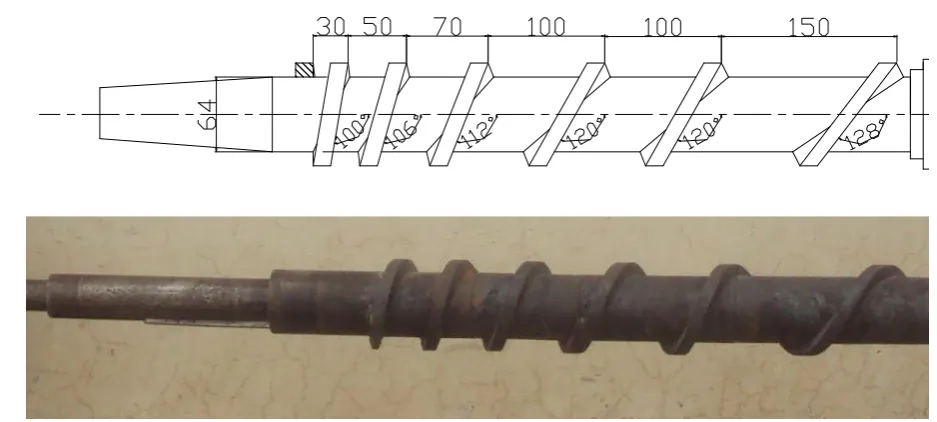
Ludhiana, India). This screw assembly (Figure 2) was
having total length as 500 mm. The flight edges of two
pitches of screw sleeves were aligned to keep the
continuity of channel. Thus unfolding the screw spiral
the screw channel looks like as tapered path as shown in
Figure 3. Therefore, the screw channel width was not
uniform. The screw channel width of each screw pitch
end of 150, 350, 420, 470 and 500 mm derived as 120, 80,
60, 40 and 25 mm respectively. The simulated results
2.2.2 Preparation of experimental set-up
The experimental set consisted of a screw-press oil
expeller (Make: Simplex Expeller Company, Ludhiana,
India) with the screw set of above configuration and a
data logger (Century Instruments Pvt Ltd, Chandigarh,
India). The temperature indicators and pressure
transducers were mounted on barrel of the screw-press at
five different length of screw barrel for recording the
temperature and pressure respectively (Figure 4).
Figure 4 The experimental set: Oil expeller fitted with
temperature and pressure transducer
The data logger was having the facilities to record the
pressure in kg/cm2 and temperature in oC.The batches of
15 kg of oilseeds of mustard (brown Indian mustard,
Brassica juncea) and sunflower (Punjab sunflower hybrid – 67, Helianthus annuus) were used for oil extraction for
experimental validation. Experiments were conducted in
triplicate. The temperature and pressure were recorded in
the data-logger, where the extracted oil was measured in
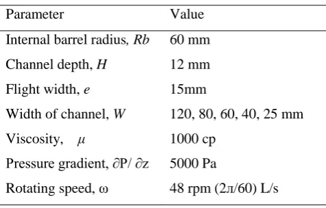
measuring flask. The designed parameters were used for
obtaining the theoretical result of velocity and pressure
profile shown in Table 1.
Table 1 Input parameters and initial values for
simulation of modifiedscrew design
Parameter Value
Internal barrel radius, Rb 60 mm
Channel depth, H 12 mm
Flight width, e 15mm
Width of channel, W 120, 80, 60, 40, 25 mm
Viscosity, μ 1000 cp
Pressure gradient, ∂P/ ∂z 5000 Pa
Rotating speed, ω 48 rpm (2л/60) L/s
3 Results and discussion
3.1 Theoretical results of modified screw design
3.1.1 Velocity distribution
The velocity profile (vz) in down channel is explained
with the help of Equation 1 by Li and Hsieh (1996) as the
velocity in the screw press is the results of drag and
pressure. The velocity profile (vz) in down channel were
Unfold screw spiral (Path of flow)
All dimensions are in mm
obtained with the help of computer programing in
Matlabsoftware (Matlab 2006) by putting the parameters
of modifies screw configuration. The combination of drag
and pressure velocity profile of developed screw is shown
in Figure 5a, Figure 5b, Figure 5c, Figure 5d and Figure
5e for the length of screw of 150 to 500 mm. The drag
flow is induced by the movement of screw root surface
and flight. The pressure flow is built-up by restriction at
the end opening (outlet) of screw press and adjustable
during operation. The channel height was 12 mm
throughout the length of screw channel. Whereas channel
width varied as 120, 80, 60, 40 and 25 mm at screw
length of 150, 350, 420, 470 and 500 mm, respectively.
Therefore, computation of down channel velocity was
done at end of each screw pitch. The velocity distribution
in channel width showed the concave trend between two
flights and similar as reported by Li and Hsieh (1996).
The velocity of flow increases with the height of channel
and maximum at edge of flight and barrel surface. The
velocity of flows also increases as material proceeds in
the pathway of channel. The flow velocities in the down
channel range from 125 to 175 mm/s through the length
of screw from 150 to 500 mm for the screw drive of 48
r/min. These results are in harmony with the down
channel velocity estimated by Ferretti and Montanari
(2007) by solving the above model equation with a finite
deferent method with the help of MS excel application.
3.1.2 Pressure profiles
The pressure profile at the different length of the
barrel was computed with the help of Equation 3. The
pressure build up in the down channel at various length of
screw is presented in Figure 6a, Figure 6b, Figure 6c,
Figure 6d and Figure 6e. The maximum pressure is built Figure 5 Velocity profile in screw channel due to a combined drag and pressure flow at 150, 350, 420, 470
at the end of screw in the range of 9 - 10.57 x 10⁵ Pa,
which is sufficient to express oil from most of the oil
seeds (Omobuwajoet al., 1999). The surface response of
pressure in screw channel is similar of the velocity profile
as concave shape. The pressure also increased toward the
end of screw length.
3.2 Experimental results and validation
3.2.1 Pressure in screw barrel
The theoretical pressure at the end of screw channel
was computation of mean value from the pressure profile.
Experimental pressures were observed with the help of
pressure transducer mounted on the barrel of the
screw-press. The predicted and experimental pressure
with screw speed of 30 and 48 r/min and for operating the
expeller with mustard and sunflower are presented in the
Table 2.
Table 2 Experimental pressure at the end of screw
Experimental and Predicted Pressure
Oilseeds
Screw Speed,
Pressure 105 Pa
Experiment Predicted % age error Mustard 30 6.51+ 0.05 6.40 1.56 48 10.57+ 0.07 10.27 2.92 Sunflower 30 6.25+ 0.04 6.40 2.34 48 9.47+ 0.05 10.27 7.78 The theoretical results of pressure were near to the
experimental observations of pressure built up with the Figure 6 Pressure distribution in screw channel at 150, 350, 420, 470 and 500 mm of screw length as (a),
per cent error ranged from 1.56 to 7.78. The pressure
built up at the end of down channel was higher for
mustard expelling as 10.57 x 10⁵ Pa at screw speed of 48
r/min. These observations also revealed that higher
pressure was built up at the higher speed of screw
revolution. The pressure obtained in the designed screw
of oil expeller was within the range of pressure reported
by Owolarafeet al. (2008) under hydraulic expression of
oil from oil palm fruits.
3.2.2Oil flow rate
The prediction of oil flow rate was computed with the
help of pressure built in screw channel and the theory
outlined in section 2.1.The predicted and experimental oil
flow rates are presented in the Table 3. The predicted
flow rate of oil is in good agreement with experimental
values. The oil flow rate was higher as 0.0052 kg/s2 at
screw speed of 48 r/min for the mustard oilseed expelling.
The observed oil flow rates were close to the predicted
values in case of expelling of mustard seeds.The variation
of experimental oil flow rates for sunflower seeds are due
to the husk of the seeds. The husk of sunflower inhibits
the flow of oil from the cells also compaction of oilseeds,
which may be observed in the lower compact density of
oil cake of sunflower seeds as 809 kg/m3 compared to
1148 kg/m3 of mustard oil cake at 48 r/min of screw
speed.The predicted results of the oil flow rate of mustard
and sunflower were same.
higher mass of oilseed were pressed. On the other hand
these results revealed that the higher oilcake density was
observed as 1248 kg/m3 at the lower speed of screw of 30
r/min. The oil extraction could be perceived with the help
of percentage oil remained in the oilcake. These results
showed that more oil could be extracted from oilseed at
the lower speed of screw due to more retention of
pressure applied. These results are agreeable with the
Vadkeet al. (1988) on the oil retention in oilcake at
different speed of screw.
3.2.3 Rate of heat generated
The heat generation was computed based on the study
state condition with help of Equation 10. Table 4 presents
the heat generated during expelling of mustard and
sunflower oil seeds at both the experimental speed of
screw as 30 and 48 r/min. These results show that
temperature increased from raw seed (32oC) ranged
between 11oC to 17oC of oil and 15to 18oC of oil cake.
The more heat was generated at higher speed of screw.
The rate of heat generation in developed screw press was
comparable to the results of Omobuwajoet al. (1998) at
the same screw revolution. The high rate of heat
generation in operation of sunflower oilseeds was mainly
the result of more friction developed by husk while
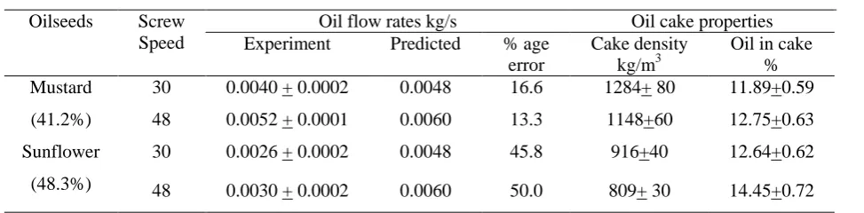
processing of whole oilseeds. Table 3 Experimental and predicted data for oil flow rates oil recovery
Oilseeds Screw Speed
Oil flow rates kg/s Oil cake properties
Experiment Predicted % age error
Cake density kg/m3
Oil in cake % Mustard
(41.2%)
30 0.0040 + 0.0002 0.0048 16.6 1284+ 80 11.89+0.59
48 0.0052 + 0.0001 0.0060 13.3 1148+60 12.75+0.63
Sunflower
(48.3%)
30 0.0026 + 0.0002 0.0048 45.8 916+40 12.64+0.62
4 Conclusion
A new set of continued screw spiral of variable size of
pitch was got fabricated for verification of the theoretical
model. This screw was having total length as 500 mm.
The pressure transducers and temperature probes were
mounted on the screw barrel for taking the observation
with the help of data logger. The pressure build up was
within range of 5 – 10.57 x 10⁵ Pa during processing the
mustard and sunflower oilseed. The oil flow rate was
higher case of mustard oilseed and with higher speed of
screw. The oil flow rate was varying between 0.0030 –
0.0052 kg/s for sunflower and mustard. The heat
generation was higher while processing the sunflower
seed and with the higher speed of screw. The heat
generation rate was between 0.4503 – 0.8002 kJ/s.The
lower speed of screw revolution resulted in more
percentage of oil expelling from oilseeds.
Nomenclature
a, b Factors defined in Equations
Ac Area coordinate, m
2
cc, co, cs, Specific heat capacity of cake, oil and
oilseed, (J/kg)/K
Db Internal barrel diameter, m
e The flight width, m
g Acceleration due to gravity, m/s2
H Maximum channel depth, m
k Coefficient of permeability, m/s
mc, mo, ms Mass flow rate of cake, oil and oilcake ,
kg/s
P Pressure, Pa
P/x Pressure gradient in the cross (width) channel direction
P/y Pressure gradient in the channel depth direction
P/z Pressure gradient in the down channel direction
qv Volumetric flow rate of flow in porous
media, m3/s
Table 4 Mass flow rates and thermo-physical properties of the mustard and sunflower oilseed, expelled oil
and the cake streams
Characteristics Mustard Sunflower
Raw seed 30 r/min 48 r/min 30 r/min 48 r/min
Temperature inlet, oC 32 32 32 32
Specific heat, (kJ/kg)/K 2.56 2.56 3.71 3.71
Mass flow rate, kg/s 0.0160+0.0004 0.0166+0.0004 0.0125+0.0003 0.0138+0.0004
Oil
Temperature inlet, oC 41+0.5 44+0.5 45+0.5 49+0.5
Specific heat,(kJ/kg)/K 1.833 1.83 1.83 1.98
Mass flow rate, kg/s 0.0040+0.0002 0.0052+0.0001 0.0026+0.0002 0.0030+0.0002
Oil cake
Temperature inlet, oC 47+0.5 49+0.5 48+0.5 50+0.5
Specific heat, (kJ/kg)/K 2.10 2.10 2.40 2.40
Mass flow rate , kg/s 0.012+0.0002 0.015+0.0003 0.010+0.0002 0.0125+0.0003
qm Mass flux, kg m
-2
/s
Qm Mass flow rate of oil, kg/s
q Rate of heat generation, kJ/s
Rb Internal barrel radius, m
Rs Screw root radius (=Rb-H), m
Tc, To,
Ts,Tr
Temperature of cake, oil, oilseed and
reference, oK
vxvyvz Component of velocity in x, y and z
directions, respectively, m/s
va Axial velocity, m/s
W Width of the channel at the internal radius
of barrel (=2Rbsinb – e), m
x Channel width coordinate, m
y Channel depth coordinate, m
z Down channel coordinate, m
Z Down channel length, m
δ Clearance of screw flight and barrel, m
ɛ Porosity, %.
Viscosity of the Newtonian fluid, Pa.s
Density, kg/m3
b Helix angle of screw Rb, rad
Rotational speed of screw, s-1
[References]
Bargale, P.C., D. Wulfsohn, J. Irudayaraj, R.J.Ford, and F.W.Sosulski. 2000. Prediction of oil expression by uniaxial compression using time-varying oilseed properties. Journal of Agricultural Engineering Research, 77(2):171-181.
Bear, J.1972.Dynamics of fluids in Porous Media.Dover Publication Inc. New York, United States.
Charlton, F. 2004.Textbook of Fluid Drynamics.CBS Publishers and Distributors, New Delhi.
Ferretti, G., and R. Montanari. 2007. A finite-difference method for the prediction of velocityfield in extrusion process. Journal of Food Engineering, 83(1):84-92.
Harmanto, A., E. Hendriadi, Rahmarestia, Mardison, and J. Wiyono. 2009. Performance test of a screw-press machine for
extracting Jatropha curcas seed into crude oil as an alternative energy sources. Indonesian Journal of Agriculture, 2(1):35-40. Herak, D., A. Kabutey, M. Monika Divisova, and S.
Simanjuntak.2013. Mathematical model of mechanical behaviour of Jatropha curcas L. seeds under compression loading. Biosystems Engineering, 114(3):279-288.
Li,Y. and F.Hsieh.1996. Modeling of flow in a single screw extruder. Journal of Food Engineering, 27(4):353-375. MATLAB 6.1 2001.The language of technical computing.The
Math Works Inc.
Mrema, G.C., and P.B. McNulty. 1985. Mathematical model of mechanical oil expression from oilseeds.Journal of Agricultural Engineering Research, 31(4):361 – 370.
Omobuwajo, T.O., Ige, M.T., and A.O. Ajayi.1998. Theoretical Prediction of Extrusion Pressure and Oil Flow Rate During Screw Expeller Processing of Palm Kernel Seeds.Journal of Food Engineering,38(4):469-485.
Owolarafe, O. K., G. A.Badmus, and M. O.Faborode.2007. Development of a permeability model for oil palm fruit cake.International Journal of Food Engineering, 3(4), DOI:10.2202/1556-3758.1042.
Owolarafe, O.K., A.S.Osunleke, O.A.Odejobi, S.O.Ajadi, and M.O.Faborode. 2008. Mathematical modelling and simulation of the hydraulic expression of oil from oil palm fruits. Biosystems Engineering, 101(3):331-340.
Oyinlola, A., A. Ojo, and L.O.Adekoya.2004. Development of laboratory model screw-press for peanut oil expression.
Journal of Food Engineering, 64(2):221-227.
Shirato, M., T. Murase, N.Hayashi, K. Miki, T. Fukushima, T.Suzuki, N.Sakakibara, and T.Tazima. 1978. Fundamental studies on continuous extrusion using a screw press.
International Chemical Engineering, 18(4):680-688.
Shirato, M., T. Murase, M. Negawa, and H. Moridera.1971. Analysis of expression operations. Journal of Chemical Engineering of Japan, 4(3):59-64.
Vadke, V.S., F.W. Sosulski, and C.A.Shook. 1988. Mathematical simulation of an oilseed press. Journal of American Oil Chemicals’ Society, 65(10):1610-1616.
Wang, L.J., G.N.Ganjyal, D.D.Jones,C.L.Weller, and M.A.Hanna.2004. Finite element modelling of fluid flow, heat transfer, and modelling of biomaterials in single screw extruder.