Mechanical behaviour of a pipe
impacted by an object, based on
numerical simulation
by Jie Zhang* and Han Zhang
School of Mechatronic Engineering, Southwest Petroleum University,
Chengdu, Sichuan, China
D
AMAGE TO A PIPE squeezed by other object are one of the key damages for oil and gas pipelines. Mechanical behaviour of a pipeline section in a deformed state was investigated by numerical simulation. Effects of initial dent depth and pipe diameter / wall thickness ratio on the mechanical behaviour of the dented pipe were studied. The results show that the squeezing force, high stress area, and the maximum stress increase in the loading process. In the unloading process, there is a high probability for recovery of the pipeline section elastic strain to initial values. Cross-section of the middle plane is flatted. The deformation of the pipe in the vertical plane is V-shaped. In the first stage, the maximum equivalent plastic strain appears in the centre part of the pipe. There are two maximum equivalent plastic strain areas with the increasing of the squeezing object’s displacement. In the unloading process, the equivalent plastic strain increases. With the increasing of the initial indentation depth, the resilient rate of the pipe dent decreases, but the maximum equivalent plastic strain increases. With the increasing of pipe diameter / wall thickness ratio, the resilient rate increases but the maximum equivalent plastic strain decreases.Keywords: numerical simulation, plastic deformation, mechanical stress, resilient rate.
*Corresponding author’s contact details: e-mail: longmenshao@163. com
Introduction
According to the latest estimates, within the next 20 years the level of energy consumption in the world will significantly increase, as will the demand for hydrocarbons. The main way oil and gas are transported is by trunk pipelines. One of the most common reasons they fail is mechanical damage, namely dents, ruptures, buckling, etc. [1]. This damage can lead to the transported product leaking and, as a consequence, to accidents, fires, and explosions. One of the most common causes of damage to above-ground pipelines is the pipe being squeezed by other objects. Therefore, it is extremely important to study the mechanical behaviour of pipeline sections which are deformed in this way.
methods [6]. G.Lu presented a simple empirical formula, which was obtained after tests on capped and uncapped pipes under the pressure of indenters located on opposite sides in the middle section
[7]. S.E.Firouzsalari determined the deformation and mechanical behaviour of pre-compressed steel pipes based on experiments and modelling using the finite-element method. However, the External object
Load
Pipe
(a) Schematic
(b) Finite-element model (a) Schematic
Time
Displacing load
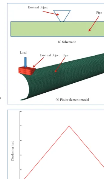
Fig. 1. Model of calculations for a pipe squeezed by a foreign object.
resulting equations are not suitable for all conditions. The mechanical behaviour of pipes is largely related to the shape and the size of the object [8].
In this paper, stresses and deformations of a pipe squeezed by another object were calculated on the basis of numerical simulation. The impact of the initial indentation depth and the ratio of the thickness and diameter of the pipe was studied to check the mechanical behaviour of the deformed section of the pipeline.
Pipe dents
The pipe squeezing leads to the formation of a dent, which is a residual equivalent plastic deformation of a circular cross-section. This is a significant distortion to the transverse cross-section of the pipe. The depth of the dent is calculated at the point of maximum reduction of the pipe diameter. The dent can be either a local indentation or any deviation from the nominal circular cross-section. Different types of pipe dents include [9]:
• smooth dents: dents that form a smooth change of the pipe walls’ curvature;
• curved dents: dents that form a
sudden change of the pipe walls’ curvature (the curvature radius of the sharpest part of the dent is at least five times less than the wall thickness);
• simple dents: smooth dents that do not reduce the wall thickness (for example, recesses or cracks) or other defects or inhomogeneities (for example, girth welds);
• free dents: dents capable of elastic recovery (straightening) after the squeezing load is removed, and capable of returning to a round shape when the internal pressure changes;
• non-free dents: dents incapable of both elastic recovery and returning to a round shape, as the squeezing load is not removed (e.g. a dent made by a stone);
• recesses: surface damage caused by contact with a foreign object, due to which the pipe has lost part of its material (the recess depth is equal to the total depth of the defect of metal loss and any crack in the base of the recess).
The finite-element model
A design scheme showing the impact of an external object on the pipe is Maximum displacement (m)
For
ce (kN)
presented in Fig.1a. The squeezing object has a triangular prism shape. The contact area of the object with the pipe is arc-shaped with a radius of 100 mm. The length of the squeezing object is greater than the diameter of the pipe. In this case there is no internal pressure in the pipe. Numerical simulation of pipe behaviour during deformation was performed using the ABAQUS software package.
Figure 1b shows the finite-element model of the pipe and its squeezing object. With regard to the general symmetry of the structure and the load applied to it, one quarter of the pipe is taken as the simulation model. The diameter of the pipe examined here is 508 mm, and its length is taken to be six times its diameter. The initial wall thickness of the pipe is 8 mm. Four-node elements of the shell with curtailed integration are used to model the cylindrical pipe. The squeezing object is modelled by eight-node elements with curtailed integration. The finite element grid is concentrated in the contact zone.
The plasticity model with isotropic strengthening is used to simulate the material of the steel which the pipe is
made of. Numerical results were obtained for X65 grade steel; this steel grade is usually used for manufacturing oil and gas pipelines. The yield strength of this steel is equal to 488 MPa; the Young’s modulus is 210 GPa; the Poisson’s ratio is 0.3; and the density of the steel is 7800 kg/m3. In the process of calculations,
a displacement load is applied to the external object. The corresponding boundary conditions are applied within the planes of symmetry. Calculations are carried out for two steps of loading: squeezing loading and unloading. The displacement load-time curve is shown in Fig.2. The initial maximum displacement of the object is equal to 160 mm.
Modelling results
Figure 3 shows the force-displacement curve for a pipe compressed by an object in the shape of a triangular pyramid. As the depth of the pipe deformation increases, the compression force increases, but the degree of displacement gradually decreases. After the maximum deformation depth reaches its limit value, the unloading process begins,
during which elastic strain is recovered. According to this study, the whole process can be divided into ten stages.
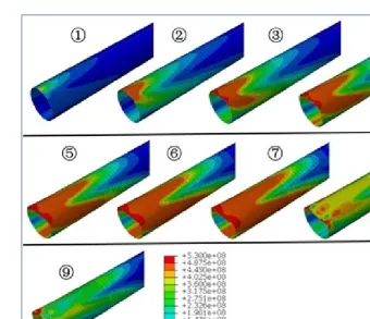
Figure 4 shows the von Mises stresses for a pipe when it is deformed by a foreign object. In the initial stage, the dent depth is very small, and high mechanical stresses are concentrated only in the upper part of the pipe. Stress distribution is oval-shaped. The pipe wall experiences only equivalent plastic deformations. As the depth of the dent increases, the zone of high mechanical stresses expands, and their values increase. In the third stage, the high-stress zone expands along the pipe in axial and circular directions. The stress distribution is mountain-shaped. The maximum stress is found in the contact zone between the pipe and the squeezing object. The stresses at the bottom of the pipe also increase. From the third to the seventh stages, the maximum stresses do not change, but the area with high stresses increases. In the seventh stage, the depth of the dent reaches its limit value of 160 mm.
In the process of loading, the stresses on the upper surface of the pipe are higher than on the lower one. The dent appears on the upper surface, and its depth is equal to the load displacement. In the eighth stage, there is a significant change
in the stress distribution during the unloading process, and the elastic strain recovers. Maximum stresses remain only on the two edges of the dent. Stresses in other areas are reduced when the load is displaced. In the ninth stage, the shape of stress distribution along the pipe becomes more stable. High stresses remain only on the two edges, but not in the central part of the pipe wall. After the seventh stage, the squeezing object no longer has contact with the pipe, so the size and distribution of the stresses do not change.
Figure 5 shows the displacement of the upper line of the pipe wall. Under compressive stress, the deformation first occurs in the contact area between the squeezing object and the pipe. Elastic strain is further formed in the adjacent area. As the load increases, the equivalent plastic strain increases and the overall
Fig.5. Plot of length (m) vs displacement (m) for the upper line of the pipe wall.
deformation of the pipe becomes more substantial. The pipe deformation in a vertical projection is V-shaped. After the seventh stage, the elastic strain recovers during unloading. Ultimately, the constant equivalent plastic strain persists after the compressing object is no longer in contact with the pipe.
Figure 6 shows the shape of the cross-section of the pipe in the middle plane. If the displacement of the squeezing object is small, the pipe cross-section becomes oval-shaped. As the displacement increases, local collapse appears. It occurs only in the top part of the pipe. Since the length of the squeezing object is larger than the diameter of the pipe, its upper surface is flattened under the impact of compression. During loading, the curvature radius of the bottom part of the pipe increases. During unloading, the elastic strain recovers, but the upper part of the pipe remains flat.
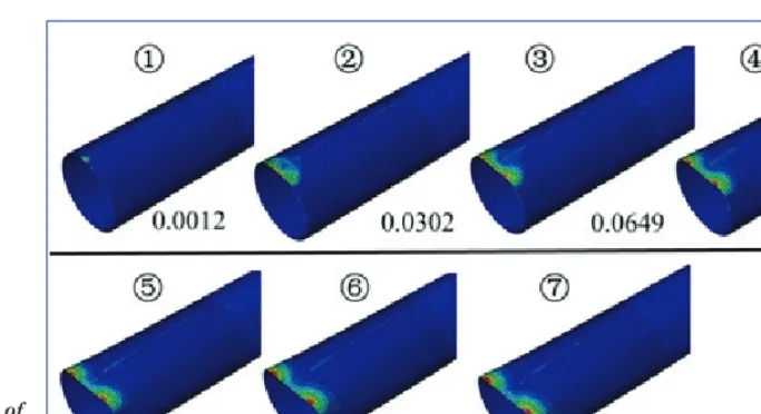
The distribution of equivalent plastic strain at different stages is shown in Fig.7. At the first and second stages, the maximum equivalent plastic strain occurs in the central part of the pipe. As the displacement of the squeezing object increases, two areas of maximum equivalent plastic strain appear at the top of the pipe. During the loading process, the equivalent plastic strain increases gradually. However, in the process of unloading it also enhances, to 0.224.
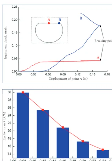
In order to describe the change in the equivalent plastic strain of the pipe more accurately, points A and B (Fig.8) may be considered. Point A is in the centre of the middle plane, and point B is the maximum equivalent plastic strain. Figure 8 shows the equivalent plastic strain curve in two points with maximum displacement. At point A, the equivalent plastic strain increases at a significant rate until the displacement reaches 0.05 m; then it increases insignificantly, at point B, there is no equivalent plastic strain at the initial stage, but during the middle stages it increases very quickly. There is only one inflection point for each of the two curves, and it marks the transition point from the loading process to the unloading process. During the unloading process, the equivalent plastic strain enhances at both points, but the rate of change at point B is greater than at point A.
The impact of sensitivity
parameters
The resilient rate k is used to describe the recovery of elastic strain in the pipe wall:
k u u
u f
= max max
-where:
umax = the maximum depth of the dent uf = the initial depth of the dent.
The resilient rate at a different initial dent depth (the limit displacing load) is shown in Fig.9. As the initial depth of the dent increases, coefficient k decreases nonlinearly. This is due to the fact that the local bend is greater than the initial depth of the dent, resulting in a decrease in indicators for elastic strain recovery.
Displacement of point A (m)
Eq
uivalent plas
tic s
tr
ain
Breaking point
Initial dent depth (m)
R
esilient r
at
e (1
00%)
Figure 10 shows the maximum equivalent plastic strain of the pipe section given different initial depth of the dent. The greater the initial depth of the dent, the higher the maximum equivalent plastic strain. However, the degree of the strain enhancement gradually decreases with the increase in the depth of the dent.
The pipe diameter / wall thickness ratio has a significant impact on the mechanical
Fig.8. The equivalent plastic strain curve for two points.
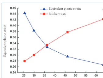
properties of the deforming section of pipeline. Figure 11 shows the resiliance rate and the maximum equivalent plastic strain given different pipe diameter / wall thickness ratios and initial dent depth of 160 mm. The resilient rate grows non-linearly as the pipe diameter / wall thickness ratio increases. This is due to the fact that higher pipe diameter / wall thickness ratio can reduce its stiffness. The maximum equivalent plastic strain of the pipe decreases with the increase in the pipe diameter / wall thickness ratio. If the pipe diameter / wall thickness ratio is less than 35, then the rate of change of the maximum equivalent plastic strain is higher. If the ratio of these parameters is higher than 35, the rate of deformation change gradually decreases.
Conclusion
Using the numerical simulation method, the study of the mechanical behaviour of a deformed pipe section squeezed by a foreign object enabled the following conclusions to be drawn:
• The compressive force, the area of high stresses, and the maximum stresses increase during the loading
process. During the unloading process, there is a significant change in the stress distribution, and the elastic strain recovers. • Under the influence of the
squeezing object, local collapse appears on the upper surface of the pipe. The cross-section of the middle surface is flat. The pipe deformation in the vertical projection is V-shaped. The maximum equivalent plastic strain appears in the central part of the pipe. When the displacement of the squeezing object increases, two areas of maximum equivalent plastic strain appear. In the unloading process, the equivalent plastic strain increases.
• As the initial depth of the dent increases, the resilient rate of the pipe decreases, but the maximum equivalent plastic strains increase. As pipe diameter / wall thickness ratio increases, the resilient rate increases and the maximum equivalent plastic strain decreases.
Acknowledgements
This research work was conducted with the support of the Key Laboratory for the Initial dent depth (m)
Eq
uivalent plas
tic s
Study of Accident and Safety Mechanisms in the Energy Sector (Sichuan University) (No. EES201604) and the Ministry of Education of China.
References
1. Z.Jie, L.Zheng, H.Chuanjun eti al., 2015. Buckling behaviour analysis of a buried steel pipeline in rock stratum impacted by a rockfall. Engineering Failure Analysis, 58, pp 281–294.
2. O.Furnes and J.Amdahl, 1980. Ship collision with offshore platforms. Intermaritec 80.
3. C.P.Ellinas and A.C.Walker, 1983. Damage on offshore tubular bracing members. Proc Int Assoc Bridge Struct Eng.
4. T.Wierzbicki and M.S.Suh, 1983. Indentation of tubes under combined loading. Int J Mech Sci, 30 pp229–248. 5. K.Chen and W.Q.Shen, 1998. Further
experimental study on the failure of fully
Pipe diameter / wall thickness ratio
Eq
uivalent plas
tic s
tr
ain
R
esilient r
at
e (1
00%)
Equivalent plastic strain Resilient rate
clamped steel pipes. Int J Impact Eng 28 (3) pp177–202.
6. C.Ruggieri and J.A.Ferrari Jr, 2004. Structural behaviour of dented tubular members under lateral loads. J Offshore Mech Arct Eng, p 126.
7. G.Lu, 1993. A study of the crushing of tubes by two indenters. Int J Mech Sci, 35 pp267–278.
8. S.E.Firouzsalari and H.Showkati, 2013. Thorough investigation of continuously supported pipelines under combined pre-compression and denting loads. International Journal of Pressure Vessels and Piping, 4 pp83–95.
9. A. Cosham and P.Hopkins, 2004. The effect of dents in pipelines-guidance in the pipeline defect assessment manual. International Journal of Pressure Vessels and Piping, 81 pp 127–139.
10. J.Zhang, Z.Liang, and C.Han, 2014. Buckling behaviour analysis of buried gas pipeline under strike-slip fault displacement. Journal of Natural Gas Science and Engineering, 21 pp 921–928.