http: // www.ijrtsm.com© International Journal of Recent Technology Science & Management 53
ISSN : 2455-9679
[Karan et al. , 4(5), May 2019] Impact Factor : 2.865
IJRTSM
INTERNATIONAL JOURNAL OF RECENT TECHNOLOGY SCIENCE & MANAGEMENT
“DESIGN & DEVELOPMENT OF FIXTURE TO ROTATES PANELS BETWEEN TWO
OPERATION”
Karan Singh Dangi
1,
Krishna Waghe
2, Satbeer Singh Bhatia
31 M.Tech. Scholar, Dept. of Mechanical Engineering, Malwa Institute Of Technology, Indore, MP, India
2-3 Assistant Professor, Dept. of Mechanical Engineering, Malwa Institute Of Technology, Indore, MP, India
ABSTRACT
This paper is present against the M.tech project work based on requirements to move and orientating radiator cooling panels of transformer between two different machine operations during manufacturing. This project will be the part as expansion of client current production line. The proposed solution or called machine is designed in such way that, required movement of panels can achieve through this mechanism. This design consist support structure made of steel just like a crane upon which driver mechanisms are mounted these mechanism are pre-developmentd and available in the market these components are working as multi axis modular system to handle panels during operations. These components are work through pneumatic energy and have basic mounting assembly and connecting mechanism arrangement.
In this paper shows that use of CAD model is essential for design, simulate part mechanism and Analysis through FEA software. Use of FEA enables us to make changes before real manufacturing of machine and also save time as well as cost of manufacturing. Solidwork software is used as FEA tool for this project and the results comes out this project is remarkable and appropriate and accepted by client.
Keyword: Pneumatic, CAD Model, FEA, Radiator cooling Panel
I.
I
NTRODUCTION1.1. What is Transformer?
Transformers are electrical machines that transform alternating current energy from one voltage to another voltage without a change in frequency. The first developed transformer was
designed in the early 1980s. The working principle of transformers depends on the Faraday’s law of induction. Voltage is generated by moving the magnet near a wire according to Faraday’s law.
This voltage is called electromotive force (emf) and denoted ɛ.
Electromotive force is directly proportional to the rate of change of magnetic flux. Transformers can be grouped into two classes according to cooling method; oil immersed transformers and dry type transformers. In this study, heat transfer and fluid flow were investigated in a radiator of an oil-immersed transformer.
http: // www.ijrtsm.com© International Journal of Recent Technology Science & Management 54
ISSN : 2455-9679
[Karan et al. , 4(5), May 2019] Impact Factor : 2.865
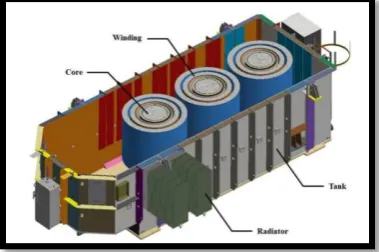
Air is used for transformer cooling in dry-type transformers. Air is directly forced into core and winding by using fans. This type of transformers has the power limits because their losses are higher. Air is used for cooling fluid to dissipate heat. Transformers consist of four main parts as core, winding, tank and accessories as shown in Figure 1.1
1.2.Radiator of Transformer
Oil immersed transformer is always provided with radiator. In case of electrical power transformer, the radiators are detachable and transported separately to the site. The upper and lower portions of the radiator unit are connected with the transformer tank via valves. These values are provided to prevent draining of oil during detaching a radiator unit from the transformer for cleaning and maintenance purposes.
1.2.1 Types of Radiators:
a) Welded/Flanged Type Radiator
b) Stainless Steel Radiator
c) Swan neck/Gooseneck type Radiator
d) Hot Dip Galvanized Radiator
1.2.2Operation and Purpose of Radiator in Transformer
When transformer is in the loaded condition, the hot oil comes up in the main tank, and enters into the radiator tank through upper valve. As the heat transfer surface of the radiator is quite large, the oil gets cooled and enters into the transformer tank via lower value of radiator units. The convectional flow of oil in the tank and radiator of transformer continues. The cooling effect of radiator can be accelerated by applying force air to the radiator outer wall by air fans.
1.2.3Function of Radiator
When an electrical transformer is loaded, the current starts flowing through it’s windings. Due to this flowing of electric current, heat is produced in the windings, this heat ultimately rises the temperature of transformer oil. We know that the rating of any electrical equipment depends upon its allowable temperature rise limit. Hence, if the temperature rise of the transformer insulating oil is controlled, the capacity or rating of transformer can be extended up to significant range. The radiator of transformer accelerates the cooling rate of transformer. Thus, it plays a vital role in increasing loading capacity of an electrical transformer. This is basic function of radiator of an electrical power transformer.
Oil immersed power transformer is generally provided with detachable pressed sheet radiator with isolating valves. But in case of small size distributing transformer, the radiators are generally integrated parts of transformer body and projected from the main tank. The working principle of radiator is very simple. It just increases the surface area for dissipating heat of the oil. In case of electrical power transformer, due to the transport limitation, these units are sent separately and assembled at site with transformer main body. At the time of dispatching, the flings of radiator are blanketed by gasket and blanketing plates. The radiator valves on the main tank are also blanketed by gasket and blanketing plates.
1.3 Cooling Modes
Cooling modes in oil-immersed transformer will be explained in this part. Transformers work in specified temperature mentioned in loading guide for oil immersed power transformers part (Part 7) of IEC 60076-7 International Standards (2005-12). All losses (iron losses and copper losses) are converted to heat energy in the transformer. Copper losses are the main source of the heat energy. The occurred heat energy increases the temperature of transformer. Transformer coolant is used to avoid overheating in transformer. Insulation paper is damaged by excess heat which is discarded by using transformer oil. Especially, radiators are used to increase the
http: // www.ijrtsm.com© International Journal of Recent Technology Science & Management 55
ISSN : 2455-9679
[Karan et al. , 4(5), May 2019] Impact Factor : 2.865
also used in power transformers as shown in Figure 1.4 that cannot be cooled using only radiators. Fans are used to drive the air on the radiator outside surfaces and pumps are used to circulate the oil into transformer tank or radiators.
II.
PROBLEM
STATEMENT
DARSHAL ENGINEERING WORKS requires conceptualizing and designing a machine assembly process capable of moving and orientating transformer radiator cooling panels between two machine operations. The proposed machine design is intended to expand its current product line by eliminating the manual panel handling process between the roll former and the spot welder. The three main panel manufacturing machines currently fabricated by it include roll form presses, spot welders and seam welders. Its current equipment design requires manual handling of each radiator panel by as many as two operators for transferring the panel from a roll form press, to the subsequent spot and seam welding operations. Current radiator panel assembly processes require that, from the roll press, the first of every two panels be manually rotated, placed and aligned on the next panel in preparation of the spot welding operation. A hydraulic arm is used to secure and push the joined panels at the indexing work station, in preparation for the final seam welding process. It requires a machine design capable of eliminating manual handling of the radiator panels, through the use of process automation.
As an essential design project requirement, DARSHAL ENGINEERING WORKS needs and hopes to build up a theoretical automated machine framework to be utilized for situating, adjusting and ordering the radiator panels as they come out of the roll form press. The machine configuration requires 180° revolution about the horizontal axis on just the first of each two panels, the capacity to oblige shifting panel dimensions and to be mechanically reliable. It likewise requires a machine design which gives a way to adjust combined panels previously ordering them into a spot welder and in arrangement of the ensuing seam welding activity. At long last, it requires a assembly design that can take out human panel handling with and enhance get together quality through increased alignment precision. All through the design process, it needs the group to think about potential varieties in assembly line infrastructure and building space, and to consider the realized different panel sizes and roll from process speed determinations. As it was hard to envision the required service hours and environmental conditions of the equipment and machines produced, it requires that any design be of high structural integrity.
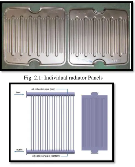
Fig. 2.1: Individual radiator Panels
http: // www.ijrtsm.com© International Journal of Recent Technology Science & Management 56
ISSN : 2455-9679
[Karan et al. , 4(5), May 2019] Impact Factor : 2.865
III.
MTEHEDOLOGY
Methodology is the systematic, theoretical analysis of the methods applied to a field of study. It comprises the theoretical analysis of the body of methods and principles associated with a branch of knowledge.
IV.
DESIGN
OVERVIEW
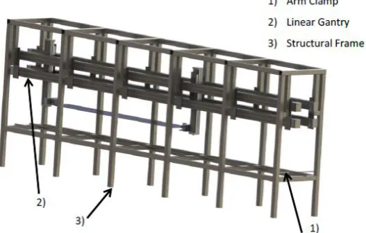
The automated panel rotation machine incorporates the use of a crane like design to rotate the first of every two panels that exits the roll former. This design essentially pulls the panel exiting the roll former from above, grabs the other end and lifts it up, rotates and places the panel back onto the bed. The next panel is picked up and placed onto the first panel at the end of the table. A variety of motions and components are used to enable the crane to achieve this task. The entire automated panel rotation machine can be seen in Fig 4.1
Fig. 4.1: Entire radiator panel rotation machine
Part involve in assembly are as follows:
4.1 Arm Clamp
The arm clamp is a device used to hold the panels as the linear gantry performs the next operation. Holding the panel is required to reduce any movement due to vibration of the system. The arm clamps rotate up and clamp down on the top surface of the panel.
Requirement Geathring
Litrature Review
Conceptulization
CAD Model Design
Design FEA Analysis
Optimization
Machine development
Time Study
http: // www.ijrtsm.com© International Journal of Recent Technology Science & Management 57
ISSN : 2455-9679
[Karan et al. , 4(5), May 2019] Impact Factor : 2.865
4.2 Structural Supports
The structural frame is the back bone of the entire design. The structure accommodates the attachments for the linear gantries and the supports for the bed. The bed is the platform onto which the radiator panels that come out of the roll former slide onto.
4.3 Linear Gantry
The linear gantry is a highly accurate, multi axis, linear motion actuator that is used to enable the horizontal (X-axis) and vertical motion (Y-axis) of the crane. The linear gantry is pneumatically actuated and consists of a horizontal support arm on which two vertical arms are mounted. These vertical and horizontal arms are complete with railing systems which allow for the movement of the two vertical arms horizontally along the top arm back and forth, as well as for the panel grippers to move up and down along to two vertical arms. Figure 5shows a linear gantry.
4.4 Top Jaw
The top jaw is a component that grips the panel around the flange area. It has the circumference of the flange and the angle of the flange riser to ensure a good grasp. There is a bottom plate that is a flat plate, which will be used to support the bottom side of the panel at the gripper jaw.
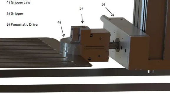
4.5 Gripper
The panel grippers are actuators that are used to move the gripper jaws. The grippers are pneumatically actuated to
enable their opening and closing motions. The pneumatic motor however, allows only for 180⁰ rotation either
clockwise or counter-clockwise. This rotation allows for rotation of the panel to either face downwards or upwards.
Fig. 4.3: Close up of gripper and pneumatic drive
4.6 Pneumatic Drive
A pneumatic drive is used in order to rotate the gripper and gripper jaw assembly. The pneumatic drive allows the
rotation of the panel while the gripper maintains a grip on the panel. It is a 180O rotating drive that works on a rack and
pinion system for precision.
V.
CAD
MODEL
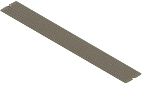
The model that was used was a replica of the 400 mm, 520 mm wide panel. It was analyzed using Finite Element Analysis (FEA) because of the complex nature of the geometry. The thin nature of the panel required that a shell mesh was performed. Fig. 5.1 shows the representative model of the panel.
.
http: // www.ijrtsm.com© International Journal of Recent Technology Science & Management 58
ISSN : 2455-9679
[Karan et al. , 4(5), May 2019] Impact Factor : 2.865
Fig. 5.1: 520x4000mm panel CAD model
The design process required the team to propose a method and mechanism for clamping and securing the panels in preparation of the panel handling process. Because of the panels’ irregularly shaped central flanged ends, special gripper jaws were designed and proposed to mount the FESTO grippers to secure the panel flange ends.
Fig. 5.2: Top gripper jaw
To completely conform to the top panel flange section geometry, an angled cut was also required on the interior of the upper gripper jaw and is illustrated in Fig. 5.3
http: // www.ijrtsm.com© International Journal of Recent Technology Science & Management 59
ISSN : 2455-9679
[Karan et al. , 4(5), May 2019] Impact Factor : 2.865
The bottom gripper jaw is shown in Fig.5.4 which holds radiator panels from botto side.
Fig.5.4: Bottom plate design
VI.
FEA
ANALYSIS
An FEA was performed to ensure that the stresses associated with supporting the panel are not too large for the gripper
jaw components. It was proven that a 450N clamp force on the panel is required. This force will have to be transmitted
though the top jaw to the point of contact. There will also be vertical force due to the weight of the panel and the
dynamic loads that is equal to 97.6N. In addition to these forces there will be a 4454N load acting in the axial direction.
Since these components are relatively small, the weight of the components themselves will be neglected as this force will not induce much variation.
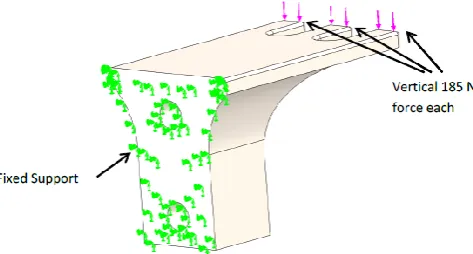
There are two steps to this FEA. First it is required to determine if the bottom jaw can support the clamp force and the weight of the panel. For a worst case scenario, both forces are placed at the end of the jaw and the jaw is fixed at the other end. These forces and fixtures can be seen in Fig 6.1
Fig 6.1: Fixed end and forces for bottom plate
When the study was run a stress of 93MPa was obtained. The same steel as the panel was used, so this is just slightly
over a factor of safety of 2.6 . The stress can be seen in
http: // www.ijrtsm.com© International Journal of Recent Technology Science & Management 60
ISSN : 2455-9679
[Karan et al. , 4(5), May 2019] Impact Factor : 2.865
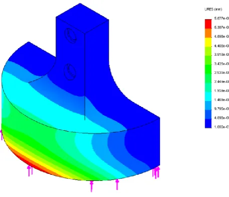
Fig. 6.3 Displacement for bottom plate
The maximum stress found in the part from the study was 16MPa. The stress found leaves a 15 times factor of safety
on yielding for this part. The stress distribution can be seen in Fig. 6.4:
Fig. 6.5: Displacement distribution for top jaw.
http: // www.ijrtsm.com© International Journal of Recent Technology Science & Management 61
ISSN : 2455-9679
[Karan et al. , 4(5), May 2019] Impact Factor : 2.865
VII.
TIME
ANALYSIS
A time analysis was conducted to help determine the time required for all steps within the automated panel handling operations. It was critical that all panel handling motions be synchronized. It was also important that the gantry arms pick up, rotate and move the first of every two panels into the indexing position and return to the roll former in sufficient time to pick up the next panel as it came out of the roll form press.
Because of the varying panel lengths, panel handling time requirements could fluctuate. The process speeds and time requirements for the varying panel lengths are detailed in Table 7.1. Although the time analysis directly relates to the gantry control systems, which is outside the scope of this project, it was nonetheless necessary that the machine component operation times be able to match the minimum panel forming times. This design time requirement was important when considering and specifying the machine components. A process time analysis was required in an effort to determine correct component specification, such as motors and actuators, and in order to provide smooth and reliable operation of the machine.
Table 7.1: Roll Forming Process Speed and Times
Roll Forming Process
Specification Value Metric
Processing Speed
1000 mm Panel 25 mm/s
2000 mm Panel 33.3 mm/s
3000 mm Panel 30 mm/s
4000 mm Panel 28.6 mm/s
Spacing Between Panels
1000 mm Panel 40 Sec
2000 mm Panel 60 Sec
3000 mm Panel 100 Sec
4000 mm Panel 140 Sec
Table 7.2 and 7.3 detail the automated machine motion sequences, as well as the times required to perform all panel handling operations. The times estimated within Table7.2 and 7.3 also allow calculating the total panel handling time. Each estimated panel handling time requirement was determined while assuming the machine components performed their operations at slower than specified speeds. The Standard LP 50 linear gantry cycle time specifications were obtained from the FESTO website the Standard LP 50 linear gantry vertical and horizontal axis stroke times were obtained from the EGC- 185-BS-KF and 2x EGC- 185 - TB – KF actuator specifications.
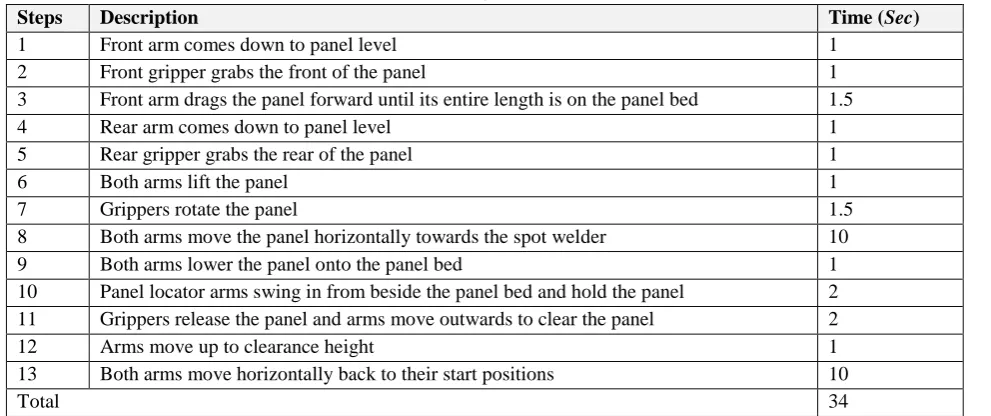
Table 7.2: Time Analysis for a 1000mm Panel
Steps Description Time (Sec)
1 Front arm comes down to panel level 1
2 Front gripper grabs the front of the panel 1
3 Front arm drags the panel forward until its entire length is on the panel bed 1.5
4 Rear arm comes down to panel level 1
5 Rear gripper grabs the rear of the panel 1
6 Both arms lift the panel 1
7 Grippers rotate the panel 1.5
8 Both arms move the panel horizontally towards the spot welder 10
9 Both arms lower the panel onto the panel bed 1
10 Panel locator arms swing in from beside the panel bed and hold the panel 2
11 Grippers release the panel and arms move outwards to clear the panel 2
12 Arms move up to clearance height 1
13 Both arms move horizontally back to their start positions 10
http: // www.ijrtsm.com© International Journal of Recent Technology Science & Management 62
ISSN : 2455-9679
[Karan et al. , 4(5), May 2019] Impact Factor : 2.865
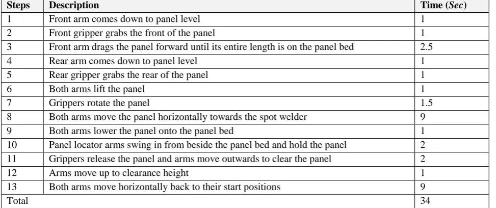
Table 7.3: Time Analysis for a 2000mm Panel
Steps Description Time (Sec)
1 Front arm comes down to panel level 1
2 Front gripper grabs the front of the panel 1
3 Front arm drags the panel forward until its entire length is on the panel bed 2.5
4 Rear arm comes down to panel level 1
5 Rear gripper grabs the rear of the panel 1
6 Both arms lift the panel 1
7 Grippers rotate the panel 1.5
8 Both arms move the panel horizontally towards the spot welder 9
9 Both arms lower the panel onto the panel bed 1
10 Panel locator arms swing in from beside the panel bed and hold the panel 2
11 Grippers release the panel and arms move outwards to clear the panel 2
12 Arms move up to clearance height 1
13 Both arms move horizontally back to their start positions 9
Total 34
As indicated in Table 7.1, 7.2 and 7.3, the 1000mm and 2000mm net panel handling times of 33 and 34 seconds are less
than the 40 and 60 second panel forming times displayed in Table 6.1. The time analysis suggests that the gantry arms will perform all panel handling operations and return to position in front of the roll former before the next panel exits the roll former. The time analysis also confirms that the specified components are capable of operating at speeds exceeding panel forming speeds.
VIII.
CONCLUSION
Due to the complexity of an integrated system like the one that has been presented, there are a number of considerations that must be mentioned. These considerations will be things that need to be analyzed and pursued further to obtain the required information.
The first limitation that caused a number of other considerations to arise was the lack of information on the linear gantry. Because the linear gantry needed for the longest panel is a newer model of an existing linear gantry, there was little specific information on it. It should perform the function it is intended to, but things such as the baseplate for mounting were not detailed. It was uncertain if it is supported at each end by two baseplates or if there are numerous baseplates that run the length of the linear gantry, with the latter being assumed in this report. With this assumption it allows the design to be more rigorous because it will have more support and the loads on the supports will be lessened.
Another consideration that was not clear with the linear gantry is how the pneumatic hoses and electrical lines will be incorporated into the design. The design presented in this report has been given some clearance on the sides of the linear gantry to allow for the cabling to be installed.
The SolidWorks model was built using some approximations due to the lack of the information above and is therefore more of a reference to how the system will work and be put together than a definite representation of the real machine. As well, cost analysis performed is an approximation and uses the resources that were available to the team.
http: // www.ijrtsm.com© International Journal of Recent Technology Science & Management 63
ISSN : 2455-9679
[Karan et al. , 4(5), May 2019] Impact Factor : 2.865
REFERENCES
1. MICHAEL STAMPFER ―AUTOMATED SETUP AND FIXTURE PLANNING SYSTEM FOR BOX-SHAPED PARTS‖
INTERNATIONAL JOURNAL OF ADVANCE MANUFACTURING TECHNOLOGY 45:540–552 DOI 10.1007/S
00170-009-1983-1,2008.
2. AJAY JONEJA ET. AL. "SETUP AND FIXTURE PLANNING IN AUTOMATED PROCESS PLANNING SYSTEMS" IIE TRANSACTIONS (1999)31,653-665
3. DJORDJE VUKELIC, UROS ZUPERL & JANKO HODOLIC "COMPLEX SYSTEM FOR FIXTURE SELECTION,
MODIFICATION, AND DESIGN"INTERNATIONAL JOURNAL ADVANCE MANUFACTURING TECHNOLOGY 2009 PP. 731-748
4. SHAUKESH S.PACHBHAI & LAUKIK P.RAUT,"AREVIEW ON DESIGN OF FIXTURES",INTERNATIONAL JOURNAL
OF ENGINEERING RESEARCH AND GENERAL SCIENCE VOLUME 2,ISSUE 2,FEB-MAR 2014, PP.126-146
5. V. M. MONTSINGER "LOADING TRANSFORMERS BY TEMPERATURE" TRANSACTIONS OF THE AMERICAN
INSTITUTE OF ELECTRICAL ENGINEERS,VOLUME:49,ISSUE:2,APRIL 1930.PAGE(S):776-790
6. Z.BOUMERZOUG &T.BAUDIN "EFFECT OF WELDING ON MICROSTRUCTURE AND MECHANICAL PROPERTIES OF
AN INDUSTRIAL LOW CARBON STEEL"ENGINEERING,2010,ISSUE:2,PAGES(S):502-506
7. EMIN BAYRAKTAR &D.KAPLAN "GRAIN GROWTH MECHANISM DURING THE WELDING OF INTERSTITIAL FREE
(IF) STEELS"JOURNAL OF MATERIALS PROCESSING TECHNOLOGY, JULY 2007,189(1-3),PAGE(S):114-125. 8. NICHOLAS AMARAL,JOSEPH J.RENCIS & YIMING RONG "DEVELOPMENT OF A FINITE ELEMENT ANALYSIS
TOOL FOR FIXTURE DESIGN INTEGRITY VERIFICATION AND OPTIMIZATION",SAETECHNICAL PAPERS ·MARCH
2002
9. SHRIKANT V PESHATWAR &LAUKIK P.RAUT "DESIGN AND DEVELOPMENT OF FIXTURE FOR ECCENTRIC SHAFT: AREVIEW"INTERNATIONAL JOURNAL OF ENGINEERING RESEARCH AND APPLICATIONS (IJERA),VOL.3,ISSUE
1,JANUARY -FEBRUARY 2013, PP.1591-1596ISSN:2248-9622
10. GUOHUA QIN, WEIHONG ZHANG & MIN WAN "ANALYSIS AND OPTIMAL DESIGN OF FIXTURE CLAMPING
SEQUENCE"JOURNAL OF MANUFACTURING SCIENCE AND ENGINEERING 128(2)·MAY 2006.
11. G. HEIDAR HASHEMI, AWALUDDIN M SHAHAROUN & S. IZMAN "RECENT DEVELOPMENTS ON COMPUTER
AIDED FIXTURE DESIGN: CASE BASED REASONING APPROACHES" HINDAWI PUBLISHING
CORPORATIONADVANCES IN MECHANICAL ENGINEERINGVOLUME 2014,ARTICLE ID484928,15 PAGES
12. BOYLE,I.,RONG,Y., AND BROWN,D.C.,―A REVIEW AND ANALYSIS OF CURRENT COMPUTER-AIDED FIXTURE
DESIGN APPROACHES,‖ ROBOTICS AND COMPUTER-INTEGRATED MANUFACTURING, VOL.27, NO.1, PP.1–12, 2011.
13. KANG,Y., RONG,Y., AND YANG,J.C., ―COMPUTER-AIDED FIXTURE DESIGN VERIFICATION—PART 1. THE
FRAMEWORK AND MODELLING,‖ THE INTERNATIONAL JOURNAL OF ADVANCED MANUFACTURING
TECHNOLOGY, VOL.21, NO.10–11, PP.827–835,2003.
14. KANG,Y.,RONG,Y.,YANG,J., AND MA,W.,―COMPUTER-AIDED FIXTURE DESIGN VERIFICATION,‖ASSEMBLY
AUTOMATION, VOL.22, NO.4, PP.350–359,2002.
15. SELVAKUMAR,S.,ARULSHRI,K.,PADMANABAN,K., AND SASIKUMAR,K.,―DESIGN AND OPTIMIZATION OF
MACHINING FIXTURE LAYOUT USING ANN AND DOE,‖ THE INTERNATIONAL JOURNAL OF ADVANCED
MANUFACTURING TECHNOLOGY, VOL.65, NO.9–12, PP.1573–1586,2013.
16. HARGROVE, S. K. AND KUSIAK, A. , ―COMPUTER-AIDED FIXTURE DESIGN: A REVIEW,‖ INTERNATIONAL
JOURNAL OF PRODUCTION RESEARCH, VOL.32, NO.4, PP.733–753,1994.
17. VALLAPUZHA, S., DE METER, E. C., CHOUDHURI, S., AND KHETAN, R. P. , ―AN INVESTIGATION OF THE
EFFECTIVENESS OF FIXTURE LAYOUT OPTIMIZATION METHODS,‖INTERNATIONAL JOURNAL OF MACHINE TOOLS
AND MANUFACTURE, VOL.42, NO.2, PP.251–263,2002.
18. VASUNDARA,M. AND PADMANABAN,K.,―RECENT DEVELOPMENTS ON MACHINING FIXTURE LAYOUT DESIGN,
ANALYSIS, AND OPTIMIZATION USING FINITE ELEMENT METHOD AND EVOLUTIONARY TECHNIQUES,‖ THE
INTERNATIONAL JOURNAL OF ADVANCED MANUFACTURING TECHNOLOGY, VOL.70, NO.1–4, PP.79–96,2014. 19. KUMAR,A. S.,SUBRAMANIAM,V., AND TECK,T.B.,―CONCEPTUAL DESIGN OF FIXTURES USING MACHINE
http: // www.ijrtsm.com© International Journal of Recent Technology Science & Management 64
ISSN : 2455-9679
[Karan et al. , 4(5), May 2019] Impact Factor : 2.865
20. NNAJI, B.O. AND ALLADIN, S. ,―E-CAFFS: AN EXPERT COMPUTER-AIDED FLEXIBLE FIXTURING SYSTEM,‖
COMPUTERS &INDUSTRIAL ENGINEERING, VOL.18, NO.3, PP.297–311,1990.
21. HUNTER,R.,RIOS,J.,PEREZ,J.M., AND VIZAN,A.,―A FUNCTIONAL APPROACH FOR THE FORMALIZATION OF
THE FIXTURE DESIGN PROCESS,‖INTERNATIONAL JOURNAL OF MACHINE TOOLS AND MANUFACTURE, VOL.46,
NO.6, PP.683–697,2006.
22. AN, Z., HUANG, S., RONG, Y., AND JAYARAM, S. , ―DEVELOPMENT OF AUTOMATED DEDICATED FIXTURE CONFIGURATION DESIGN SYSTEMS WITH PREDEFINED FIXTURE COMPONENT TYPES: BASIC DESIGN,‖
INTERNATIONAL JOURNAL OF FLEXIBLE AUTOMATION AND INTEGRATED MANUFACTURING, VOL.7, NO.3, PP.
321–341,1999.
23. KUMAR,A.S.,FUH,J.Y.H., AND KOW,T.S.,―AUTOMATED DESIGN AND ASSEMBLY OF INTERFERENCE-FREE