[
r'
[
[
[,
[:
[
CONTROL DATA
8955 PAGE AND DOCUMENT
READER CONTROLLER
CONTROL DATA
CORPORATION[-'
-[
[:
D
o
C'
~,
L.;·
REVISION RECORD
REVISION
DESCRIPTION
A Manual Released. (6-15-71)
B Manual revised; includes Engineering Change Order 29723 publications change only. Pa!!es (11-1-71) revised: iii, vi, 1-2, 1-3, 1-5, 1-9, 1-10, 2-1, 2-2, 2-3, 2-4, 2-5, 2-6, 2-7. Pages added:
2-8 throus:rh 2-12
C Manual revised; includes Engineering Change Order 30685, publication change only. Pages 1-7, (2-1-72) 3-3, 3-9, 3-11, 3-14, 3-15, 3-16, 3-22, 3-23, 3-24, 3-25, 3-26, 3-27, 3-28, 3-31, 3-32, 3-33,
3-34, 3-35, 3-37, and Comment Sheet revised. Pages 3-39 and 3-40 added. D Manual revised;' includes T~L Controlware Version,S. 0,
(1-10-74)
~'.
Publication No. 60324600
© 1971, 1972, 1974
by Control Data Corporation
Printed in the United States of America
"
,
,
-Address comments concerning this manual to:
Control Data Corporation OCR Operations
1455 Research Boulevard Rockville, Maryland 20850 or use Comment Sheet in the back of this manual.
u
o
o
c
c
r
,
~'
~.
I
c
c
c
c
c
c
()
C
o, ,.,>,'c
[
[
[
PREFACE
The following publications contain additional reference information applicable to the CONTROL DATA® 955 Page and Document Reader system.
Title
955 GRASP OCR Software Reference Manual
Tape SCOPE OCR Software Reference Manual
955 SETUP OCR Software Reference Manual
DRA FT OCR Software Reference Manual
Pub. No.
48430000
48430010
48430050
48143900
955 OCR Media Manual 60216102
CJ122 Page and Document Reader Hardware
Reference / Customer Engineering Manual 48430080
FFI04-A Page and Document Reader Controller,
and 1700 A /Q Coupler Customer Engineering
Manual 60324700
Refer to the Control Data Literature Distribution Service catalog for latest revision levels of the above publications.
u
o
o
c
G.""i
V
o
c
c
c
c
o
..
c
o
C
'~'"
CONTENTS
1 GENERAL DESCRIPTION 1-1 Autoload Control Mode (D= 9) 3-17
System Highlights 1-1 Director Status 3-18
Operating Characteristics 1-1 System Status (D= 1) 3-18
Physical Description 1-3 Ready 3-19
Functional Description 1-6 Busy 3-19
Page A dvance Control 1-6 Interrupt 3-19
Mirror Control 1-6 Data 3-19
Read Control 1-6 End of Operation 3-19
Document Marking Control (Option) 1-7 Alarm 3-19
Sort Control 1-7 Lost Data 3- 20
Program Protect 3- 20
2 OPERATION 2-1 Autoload 3- 20
Line Delete 3- 20
Controls and Indicators 2-1 Character Reject 3-20
Line Locate Failure 3- 20
3 PROGRAMMING 3-1 End of File 3- 21
[
c
(
[
[
"/
[~
Introduction 3-1 Transport Status Fa ult 3- 21
I/O Communication 3-1 Document No Sort 3- 21
Converter Code 3- 2 Data Skewed 3- 21
Equipment Code 3-2 Transport Status (D=2) 3-21
Data Transfer 3-5 Mirror Position Status 3- 21
Director Functions 3-5 Mirror/ Transport Fault 3- 21
Introduction 3-5 Document Length Fault 3- 22
Coupler Mode (D= 1) 3-5 Parameter Fault 3- 22
Clear Controller 3-5 Mirror Stop Fault 3- 22
Clear Interrupt 3-5 Coordinate Fault 3- 23
Data Interrupt Request 3-7 Mirror Velocity Fault 3- 23
End of Operation Interrupt Scan Gate 3- 23
Request 3-7 Data Transfer Words (D=O) 3- 23
Alarm Interrupt Request 3-7 Table Identifier 3- 24
Parameter Mode (D= 2) 3-8 Stylized Print 3-24
Scan Mode 3-9 Alternate Font Line Number 3- 24
Parameter Word Count 3-10 Horizontal Pitch 3-24
Position Mode (D= 3) 3-10 ANSI Lower Case 3-24
Terminating Mirror Coordinate 3-11 A NSI Font Select 3-24
Page A dvance Count 3-11 ANSI OCR-A Size IV 3- 25
Pitch Selection 3-11 Handprint Font Word 3- 25
Enable Page Advance Increment 3-11 Table Idelltifier 3- 25
Mechanical A ction Mode (D=4) 3-12 Handprint 3- 25
Read Mode (D=5) 3-14 Horizontal Pitch 3- 25
Initial Mirror Coordinate 3-14 No Leading A NSI Character 3-26
Terminal Mirror Coordinate 3-15 European 1 and 7 3- 26
Line Locate Mode (D= 6) 3-15 A
scn
Output Codes 3- 26Read Coordinates 3-15 Gothic QSE 3- 26
A utoload Director Function 3-16 Suppress Leading A NSI Character 3- 26
Introduction 3-16 Handprint Subfields ID=7 3- 26
Autoload Data Mode (D=8) 3-16 Table Identifier 3- 26
Data Words 3-16 Field Word 3- 27
Table Identifier 3- 27
u
o
o
End of Record Mark 3-28 Reverse Shift 3- 35
Initial Field Coordinates/Terminal Scan Right-to- Left 3- 35
Field Coordinates 3-28 Reverse Buffer 3- 35
Video Control Word ID=5 3-29 Terminating Mirror Coordinate 3-35
Table Identifier 3-29 Rescan Word ID=E 3- 36
Character Peak Reference 3-29 Table Identifier 3- 36
Video Quantizing 3-30 Control Count 3- 36
Line Width Control Word ID=.6 3-30 Document Ready Advance Word
Ta ble Identifier 3-30 ID=F 3-36
Horizontal Line Thickening 3-30 Table Identifier 3- 37
Vertical Line Thickening 3-31 Document Ready Advance Count 3-37
Character Control Words 3-31 Interrupt Signals 3-37
c
Table Identifier 3-32 Interrupt on Data 3-37
Delete Line Word ID=B 3-32 Interrupt on End of Operation 3-37
Table Identifier 3-33 Interrupt on Alarm 3-37
c
Blank Line Word ID= C 3-33 Handprint Option 3-37
Table Identifier 3-:34 Handprint Symbol Data 3-38
Document Length 3-34 Handprint Alpha Data 3-38
Relative Blank Line Mirror Count 3-34 Handprint Numeric Data 3-38
Mirror Image Word ID=D 3-34 Low Data 3-39
Tdble Identifier 3-35 Error 3-39
Upside- Down 3-35 High Data 3-39
Handprint Character Identifier 3-39
FIGURES
1-1 Page and Document Reader 1-4 3-12 Font/Field Word Format 3-23
1- 2 Typical Reader System 1-5 3-13 Handprint Font Word Format 3- 25
2-1 Document Loading 2-5 3-14 Handprint Subfield Word Format 3- 27
2- 2 Reader Control Panels and 3-15 Field Word Format 3-28
Feedup Table 2-7 3-16 Field Coordinates 3- 29
2-3 Operator Control Panel 2-8 3-17 Field Coordinates 3- 29
2-4 Document Adjustment Panel 2-12 3-18 Video Control Word Format 3- 29
2-5 Journal Tape Control Panel 2-13 3-19 Line Width Control Word Format 3- 30
2- 6 Journal Tape Option 2-15 3-20 End of Line Word Format 3-31
3-1 Q Register Format 3-1 3-21 Cancel Character Word Format 3-32
3-2 Coupler Mode Format 3-7 3-22 Character Delete 3-32
3-3 Parameter Mode Format 3-8 3-23 Character Delete 3-32
3-4 Position Mode Format 3-10 3-24 Delete Line Word Format 3-33
3-5 Mechanical Action Mode Format 3-12 3-25 Blank Line Word Format 3-33
c
3- 6 Read Mode Format 3-14 3-26 Mirror Image Word Format 3-34
3-7 Line Locate Mode Format 3-15 3-27 Mirror Image Read Format 3-35
3-8 A utoload Data Mode Format 3-16 3-28 Rescan Word Format 3-36
c
3-9 A utoload Control Mode Format 3-17 3-29 Document Ready A dvance Word
3-10 System Status Format 3-18 Format 3-36
3-11 Transport Status Format 3-22 3-30 Handprint CodeWord Format 3-38
o
TABLES
1-1 Reader Operating Characteristics 1-2 2-1 Power Turn-On Procedure 2-2
c
1-2 Reader Physical Characteristics 1-5 2-2 Reader Document Loading
1-3 Reader Options 1-7 Procedure 2-2
o
vi 60324600 D
C'
c
2-3 Corrective Action Procedures 2-8 Journal Tape (Option) LoadingFor Reader Halts 2-6 Procedure 2-13
2-4 Power Shut- Down Procedure 2-6 3-1 Function and Status Codes 3-2
2-5 Operator Control Panel Controls 3-2 Data Transfer Words 3-3
C"
/And Indicators (S/ N 103-150) 2-8 3-3 Character Cross Reference
2-6 Document Adjustment Panel 2-12 Chart 3-6
2-7 Journal Tape Control Panel (See A-1 Conversion Table A-1
Figure 2-5) 2-13
['
[
[ .>
, '
[
(
" "/
(
(
[,"
u
o
;('~-,
\ljf'
C'
zr'
'~
"
c
'···.-.~.'···I '
C·
l' ~ .
I e · . ' "
J
•
o
c
D
()
['
~)
SECTION 1
GENERA L DESCRIPTION
The CONTROL DATA® Page and Document Reader Controller provides the logic interface for the Control Data 955. a multi-purpose optical character recognition (OCR) peripheral device designed for business data processing. The reader optically reads printed pages and documents and is capable of handling a wide variety of form layouts and sizes. Its high resolution optics enable it to read degraded or distorted print (as on carbon copies. for example). unevenly spaced or unevenly printed copy (as from high-speed printers). or poorly inked impressions (as from embossed-card imprinters). The basic reader reads a subset of the American National Standards Institute (ANSI). Size A cha l"lcter set; however. optional equipment may be added to the reader to enable reading a number of other type
fonts. including handprint (s~e Table 1-3). For further information concerning print
spec-ifications. line spacing. forms design. and related topics. refer to the 955 OCR Media Man-ual (Pub. No. 60216102).
SYSTEM HIGHLIGHTS
Highlights of the system include:
Free field definition
User choice of control symbols Field resequencing
Input field size checking
Input field contents checking (alpha/numeric) Header and trailer label options
Code conversion capabilities Document size choice
Sorting and marking for error documents Tape density and parity control
Eight input record formats
A ccumulation of selected numeric fields Field duplication
Optional use of stock or pre-printed forms User exit for special data manipulation (optional)
OPERATING CHARACTERISTICS
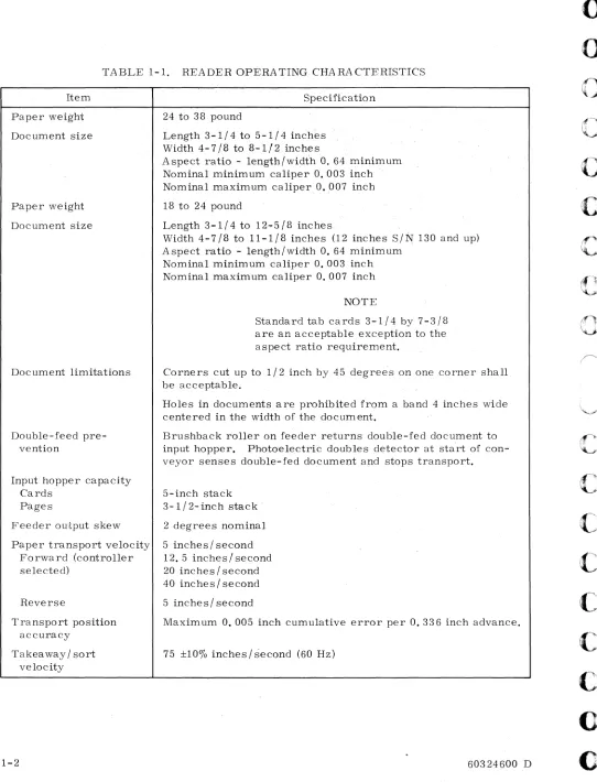
Operating characteristics of the reader are listed in Table 1-1.
TABLE 1-1. READER OPERATING CHARACTERISTICS Item
Paper weight
Document size
Paper weight
Document size
Document limitations
Double-feed pre-vention
Input hopper capacity Cards
Pages
Feeder output skew
Paper transport velocity Forward (controller selected)
Reverse
Transport position accuracy
Takeaway/sort velocity
1-2
Specification
24 to 38 pound
Length 3-1/4 to 5-1/4 inches Width4-7/8to 8-1/2 inches
A spect ratio - length/width O. 64 minimum
Nominal min~mum caliper O. 003 inch .
Nominal maximum caliper O • .007 inch
18 to 24 pound
Length 3-1/4 to 12..,.5/8 inches
Width 4-7/8 to 11-1/8 inches (12 inches S/~ 130 and up)
A spect ratio..,. length/width 0; 64 minimum Nominal minimum caliper 0.003 inch Nominal maximum caliper 0.007 inch
NOTE
Standard tab cards 3-1/4 by 7-3/8 are an acceptable exception to the aspect ratio requirement.
Corners cut up to 1/2 inch by 45 degree's on one corner shall be acceptable.
Holes in documents are prohibited from a band 4 inches wide centered in the width of the document.
Brushback roller on feeder returns double-fed document to input hopper. Photoelectric doubles detector at start of con-veyor senses double-fed document and stops transport.
5-inch stack 3-1/2- inch st;3.ck '
2 degrees nominal
5 inches/ second
12. 5 inches
I
second20 inches / second 40 inches/ second
5 inches/ second
Maximum 0.005 inch cumulative error per 0.336 inch advance.
75 ±100/0 inches/second (60 Hz)
60324600 D
u
o
o
o
C"
, ,c
c
c
C
,,·
,c
c
o
..
[image:10.612.55.597.42.752.2]c
c
C
"'I " /(
"'". I,)"
[
[
[
[
c
D
c'
TABLE 1-1. READER OPERATING CHARACTERISTICS (CONT'D)
Item Specification
Type font
ANSI OCR-A Size I A NSI alphanumeric set includes upper case A through Z, 0
and Size IV through 9, plus following symbols: apostrophe, semicolon,
cancel, quotes, plus, right parenthesis, left parenthesis, asterisk, slash. minus, percent sign, comma, ampersand, dollar sign, period, colon, up fork, chair, equals, and hook.
Scan rate 75 inches / second
Power
60 Hz (60 to 59 -0.6 Hz) 208 ±10% vac, 30 amps/phase, 3-phase, wye connected with
50 Hz (49. 2 to 50.5 Hz) ac neutral and earth ground.
Instantqneous reading rate
955 Reader input current
Operating Start-up Standby
Operating power av-erage
Ambient temperature range
Operating Storage
Relative humidity
Operating Storage
Heat dissipation
Altitude
Cooling
Forced air
PHYSICAL DESCRIPTION
750 characters/second (when character pitch = 10 characters
per inch)
12 amps/phase
200 amps /phase, single cycle 2 amps, single phase
6.6 kva
60" to 800 F
30"toI50°F
30% to "60%
5% to 95% (no condensation)
23,800 BTU /hour
-1,000 ft. to 6, 000 ft. above mean sea level
1000 cfm, max. inlet temp. 800 F
The reader is housed in a pair of welded-frame modules, each having casters to facilitate moving it into position and adjustable feet for leveling purposes. The conveyor, stacker, sorter, power control unit, optics system, read electronics, reader power supplies, and vacuum and compressed air systems are mounted in the reader module, and the controller, its associated power supplies, the cooling system, and the feedup table are housed in the controller module. Before operation, both modules are bolted together to form the unit shown in Figure 1-1. Physical characteristics of the reader are listed in Table 1-2.
READER MODULE
CONTROLLER MODULE
[image:12.612.67.597.40.480.2][J
Figure 1-1. Page and Document Reader
The controller, including 4K memory stack and associated contro} circuits, occupies a space approximately 19 inches wide, 30 inches high, 12 inches deep in the back portion of the controller module cabinet. All electrical power required by the controller is supplied by the dc power supply in the controller module.
Readers with serial numbers below 151 were designed to function with separate configura-tors for the reader and the controller. Readers with serial numbers above 150 were
designed to function with a controller included in the reader configurator. There are minor differences in the physical appearances of the two controllers and in the electronic circuits of each. However, logically they operate and function the same way. In addition, each type of controller is documented in a separate set of publications. The basic CE hardware reference manual for controllers in :readers below serial number 151 is publication number 60324700 and for controllers in readers with a serial number above 150 the publication number is 48935300. Figure 1-2 depicts a Typical J:{eader System block diagram.
60324600 D
u
o
o
o
c
o
c
c
o
r\
~;~
C·\
.... :.Jc
(
",-~.'
r-(
c:
[
(,
(:
()
O
L .,.C···
c., ..TABLE 1-2. READER PHYSICAL CHA RA CTERISTICS
Item Specification
Weight
Reader module 1400 pounds'
Controller module 400 pounds
Dimensions
Reader module height 57 inches
width 72 inches
depth 34 inches
Controller module height 48-1/2 inches
width 26-1/4 inches
depth 34 inches
Reader assembled height 57 inches
width 98-1/2 inches
depth 34 inches
TELETYPE-WRITER
STATUS, DATA
•
SENSE ,DATA STATUS,DATA
READER
CONTROL CONTROLLER STATUS COMPUTER
STATUS, DATA
Ir
MAGNETIC STATUS ,DATA MAGNETIC
TAPE TAPE
TRANSPORT CONTROLLER
R3U002
Figure 1-2. Typical Re;3.der System
[image:13.612.75.494.92.718.2]FUNCTIONAL DESCRIPTION
Pages or documents to be read are loaded onto a feedup table on the reader and transported individually on vacuum belts to the read area where they are scanned a line of information at a time. as directed by the program in the computer. Light reflected from the area occupied by a single character is converted into electrical signals which are analyzed to determine the character read. After all characters in a line are. read, a block of character data is transferred to the computer, and the document is advanced to the location of the next line that is to be read. After all lines on the page have been read, the document is moved
out of the read area by a sort command and sorted into one of two output hoppers.
PAGE ADVANCE CONTROL
Each document moves to and through the read area under control of the computer and the controller. A Director 3 (Positioning Mode) function code is used to provide the page advance step size and count. Under program control documents can be moved at. the rate of 6, 5-1/3, 5, or 4 lines per inch or in small steps of 0.040 inch. Documents need not stop at the Docu-ment Ready position on the reader, but may be advanced directly to the first line on the page. This is done while the previous document is sorted. At the read area the documents are formed into a concave surface, accurately located to be in focus for scanning.
MIRROR CONTROL
On receipt of programmed instructions, the controller applies signals to the reader to cause the line scanning mirror to move in a forward direction (left to right), reverse direction
(right to left), stop, or return to zero horizontal-coordinate position. Line sweeps are accomplished by issuing the starting and stopping points (initial and terminal mirror coordinates), and a Director 4 (Mechanical Action) function code is used to zero the line
scanning mirror. It should be noted that the mirror coordinate system can be reversed
end-for-end using the Scan Right to Left bit in the Mirror Image Word (Character Control Word, HEX D).
Each line of characters is scanned at a velocity of 75 inches per second at the paper surface. When returning to read the next line (sometimes referred to as "flyback") the scanning
mirror normally undergoes constant acceleration until it reaches the approximate midpoint
of the next line to be scanned, and then constant deceleration to a velocity plateau and then deceleration until it stops at the desired coordinate. Adc motor drives the scanning system,
and a shaft encoder provides position signals for every O. 048 inch of scan travel across the
paper.
Mirror direction instructions are normally combined with page advance instructions. This reduces the line-to-line transition time since the mirror will move toward the new coor-dinates at the same time that the page is advancing to bring the new line of information to the read area.
REA D CONTROL
Director 5 (Read Mode) function codes provide the initial and terminal mirror coordinates which determine where reading will start and stop. A s each character on the line is read, the reader translates it and provides a binary code (representing that character) to the controller. When the end of the line is reached. the controller will prepare for a block transfer of data to the computer. During the Read operation the normal scan height is three characters. This provides the largest allowable character misalignment in each line of
1-6 60324600 D
v
o
o
c
C'·
.,c
c
c
c
o
c
o
o
(
,-,>·F
[,
~/
D
information; however, to avoid image overlap, line density on the document must be no more than three lines per inch.
DOCUMENT MARKING CONTROL (Option)
A Director 4 (Mechanical Action Mode) function can also be used to instruct the reader to place a small mark on the left-hand margin of the document alongside of the line being read. Marking the document in this manner may be accomplished for any reason at the discretion of the programmer.
SORT CONTROL
After the last line of a document is read, the reader moves the document to one of the two sort pockets. A Director 4 (Mechanical Action Mode) function code selects the sort pocket that is to receive the document, and the reader moves it to that pocket. All documents are normally placed in the primary sorting hopper, and the exceptions are sorted into sort pocket 2.
Option
Handprint Numerics
ANSI OCR-A Size IV
Marking Pen
Journal Tape
On-Line Reject Correction
Six lines linch
Mirror Image
60324600 D
TABLE 1-3. READER OPTIONS
Description
o
through 9, plus, minus, equals, field mark, and uppercase C, S, T, X, and Z. Field or factory installed.
Changes optical scaling of reader when installed and is selectable under program control. Factory installed only.
Solenoid-activated device with pen that places circle on document's left margin, under program control. Field or factory installed.
Feed spindle and driven spool with tape hold-down idler arms. Width ranges from 3 to 4-1/2 inches. Maximum roll diameter is 4 inches. Minimum character field is 12 inches. Minimum trailer is 30 inches. Factory installed only.
Self-contained cathode ray tube (CRT) and keyboard video display shows characters on either side of rejected char-acter. Operator corrects on-line by code insertion via keyboard. Field or factory installed.
Enables reader to read characters spaced at six lines to the inch or less. Modular logic assembly added to logic rack. Contains full character buffer memory, line track-ing logic, and timtrack-ing and control logic. Factory installed only.
Program and associated electronics enables reader to read characters in normal position, reverse position, and
mirror image of each: B, 8:, B, H. Provides right to left
scan capabilities.
[image:15.612.61.550.314.768.2]1-8
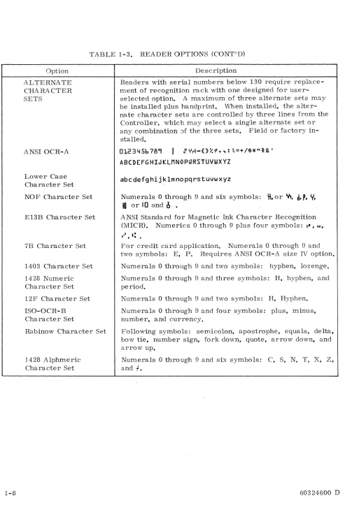
TABLE 1-3. READER OPTIONS (CONT.'D)
Option
ALTERNATE CHARACTER SETS
ANSI OCR-A
Lower Case Character Set
NOF Character Set
E13B Character Set
7B Character Set
1403 Character Set
1428 Numeric Character Set
12F Character Set
ISO-OCR-B Character Set
Rabinow Character Set
1428 Alphmeric Character Set
Description
Readers with serial numbers below 130 require replace-ment of recognition rack with one designed for user-selected option., A maximum of three alternate sets may be installed plus handprint. When installed, the alter-nate character sets are controlled by thre.e lines from the Controller, which may select a single alternate set or any combination Jf the three sets. Field or factory in-stalled.
0123456789
I
J' YrI-{}%?,: ;=+/$*"t& 'ABCDEFGHIJKLMNOPQRSTUVWXYZ
abcdefghijklmnopqrstuvwxyz
Numerals 0 through 9 and six symbols:
\'I,
or y"d. P. Y.
10
or 10 and1I .•
ANSI Standard for Magnetic Ink Character Recognition
(MICR). Numerics 0 through 9 plus four symbols: II" • • 11.
For credit card application. Numerals 0 through 9 and
two symbols: E, p. Requires ANSI OCR-A size IV option.
Numerals 0 through 9 and two symbols: hyphen, lozenge.
Numerals
o
through 9 and three symbols: H, hyphen, andperiod.
Numerals 0 through 9 and two symbols: H, Hyphen.
Numerals 0 through 9 and four symbols: plus, minus, number. and currency.
Following symbols: semicolon, apostrophe, equals, delta. bow tie, number sign. fork down. quote, arrow down, and arrow up.
Numerals 0 through 9 and six symbols: C, S, N, T, X, Z,
and
f.
60324600 D
o
o
c
c
c
c
c
c
c
C·
., -'.c
c
o
[image:16.612.56.569.28.771.2]C·'
.,."~ I
C
'.-."I_I
[)
[
c
r
L.
c
[
[
D
D
SECTION 2
OPERATION
This section contains operating procedures for the reader, lists of controls and indicators and their functions, and illustrations showing the physical locations of the controls and
indi-cators. Tables 2-1, 2-2, 2-4, and 2-8 contain operating procedures in step-by-step format
showing where each step is performed, action to be taken, and the results of the action.
Table 2-3 lists corrective action procedures to be followed when document feeding problems
occur. For operator convenience, each of these tables starts on a separate page.
CONTROLS AND INDICATORS
The controls and indicators on the reader are described in Tables 2-5, 2-6, and 2-7, which
are keyed to Figures 2-3, 2-4, and 2-5 respectively. In these tables, the Ref column lists
the figure call-out number, the next column gives the panel name for the control or indicator, and the Function column states the functional purpose or use.
[image:17.612.48.554.300.770.2]Step 1 2 3 Step 1 2 3 4 5 6 7 2-2
TABLE 2-1. POWER TURN-ON PROCEDURE
Equipment Procedure
Operator Control Press POWER ENABLE pushbutton indicator.
Panel (See Fig-ure 2-2)
Press CONTROLLER POWER pushbutton indicator·
(SIN 103 and up, only).
Press READER POWER pushbutton indicator.
NOTE
Reader will not come .on unless con-troller is on (SiN 103 and up) . . Reader will not function unle s s Controlware is loaded in controller.
TABLE 2-2. READER DOCUMENT LOADING PROCEDURE
Equipment
Operator Control Panel
Feedup table (See Figure 2-1)
Feedup table
Document adjust-ment panel
Sort pockets
Feeder assembly
Document A djust-ment Panel
Procedure
Ensure POWER ENABLE. READER POWER. and CONTROL-LER POWER indicators are lit. Refer to Table 2-1 for power turn-on procedure.
Disable feedup and pull wedge, shown in Figures 2-1 and 2- 2, back far enough so that a shingled stack of documents will fit on the belt without hitting the stationary ramp on the feeder.
Put sample document to be processed into feedup table.
A djust guide walls to within 1
18
inch of document edge bymanipulating PAPER GUIDE WIDTH ADJUST switch.
Place sample document in both sort pockets and adjust back plate until pocket length is 1/2 inch longer than document.
Adjust stacker width guides until pocket width is 1/2 inch
wider than document.
Place sample documents on feedup table.
Press ENABLE FEED UP pushbutton.
Repeatedly press LOAD switch to advance documents from feedup table while turning DOCUMENT THICKNESS ADJUST knob counterclockwise (thicker documents) until double document feed occurs.
Then turn DOCUMENT THICKNESS A DJUST knob clockwise (thinner documents) until double document feed no. longer occurs.
60324600 D
[image:18.612.55.565.68.752.2][
L.
D
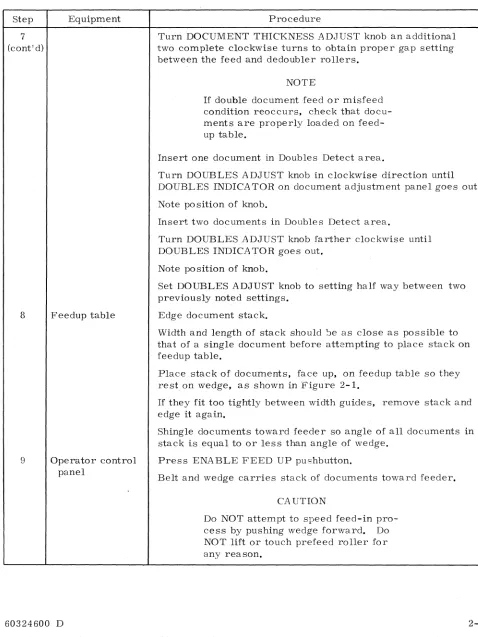
TABLE 2-2. READER DOCUMENT LOADING PROCEDURE (CONT'D)
Step
7 (cont'd)
8
9
Equipment
Feedup table
Operator control panel
60324600 D
Procedure
Turn DOCUMENT THICKNESS ADJUST knob an additional two complete clockwise turns to obtain proper gap setting between the feed and dedoubler rollers.
NOTE
If double document feed or misfeed
condition reoccurs. check that docu-ments are properly loade.d on feed-up table.
Insert one document in Doubles Detect area.
Turn DOUBLES ADJUST knob in clockwise direction until DOUBLES INDICATOR on document adjustment panel goes out.
Note position of knob.
Insert two documents in Doubles Detect area.
Turn DOUBLES ADJUST knob farther clockwise until DOUBLES INDICA TOR goes out.
Note position of knob.
Set DOUBLES ADJUST knob to setting half way between two previously noted settings.
Edge document stack.
Width and length of stack should ~e as close as possible to
that of a single document before attempting to place stack on feedup table.
Place stack of documents. face up. on feedup table so they rest on wedge. as shown in Figure 2-1.
If they fit too tightly between width guides. remove stack and
edge it again.
Shingle documents toward feeder so angle of all documents in stack is equal to or less than angle of wedge.
Press ENABLE FEED UP pushbutton.
Belt and wedge carries stack of documents toward feeder.
CA UTION
Do NOT attempt to speed feed-in pro-cess by pushing wedge forward. Do NOT lift or touch prefeed roller for any reason.
[image:19.612.51.529.116.753.2]Step
9
(cont'd)
10
11
2-4
TABLE 2..,2, READER DOCUMENT LOADING PROCEDURE (CONT'D)
Equipment
Feedup table
Operator Control Panel
Procedure
When the wedge stops press the LOAD pushbutton to advance documents from feedup table to read station,
Press READY pushbutton indicator,
READY lights,
Documents are ready to be processed,
To load more documents of the same size, wait until feedup table is clear of all documents, then repeat procedure from Step 9,
CAUTION
Extreme caution should be taken when loading more documents while previous load is still being fed in,
To load more documents of the same size but different thickness, repeat procedure from Step 6,
When a sort pocket is full, SORT POCKET FULL indicator lights, Reader stops,
Remove documents from sort pocket,
SORT POCKET FULL indicator goes out when the READY or LOAD switch is pressed,
NOTE
Documents may be removed from sort pocket during operation,
Repeat procedure from Step 10,
60324600 D
o
o
c
c
c
c
c
c
(~
c
(J
r;\
Li'
-
..60324600 D
A. PROPER DOCUMENT LOADING:
1. WEDGE PULLED SUFFICIENTLY BACK ON BELT. 2. DOCUMENTS SHINGLED TO ANGLE OF WEDGE.
B. IMPROPER DOCUMENT LOADING:
1. WEDGE NOT PULLED BACK FAR ENOUGH.
2. DOCUMENTS IMPROPERLY SHINGLED AND JAMMED TOGETHER.
Figure 2-1. Document Loading
Step
1
2
Step
1
2-6
TABLE 2-3. CORRECTIVE ACTION PROCEDURE FOR READER HALTS
Malfunction Procedure
Sort paper jam. .. Paper jam in sorting mechanism automatically stops reader.
SORT CHECK lights,
At sort gate,remove jammed paper and deposit in sort
REA DY goes out. pocket.
Double document feed
DOUBLES CHECK lights, READY goes out.
At operator control panel, press READY.
REA DY lights.
Reader stops. Remove all double feeds and return them to feedup table. At feeder, adjust redoubler roller (refer to Step 7 of Table 2- 2).
At Operator Control Panel press ENABLE FEED UP, and READY.
ENABLE FEED UP and READY light.
TABLE 2-4. POWER SHUT-DOWN PROCEDURE
Equipment Procedure
CAUTION
In an emergency, press POWER ENABLE
pushbutton indicator on operator control panel to turn off ac and dc power to reader and controller. POWER ENABLE goes out.
Operator control Press READER POWER pushbutton indicator.
panel
READER POWER goes out.
60324600 D
u
o
o
c
c
~
I' -,'
~
c
c
c
C
",'
c
c
c
t~
C;\
~~.,;;C
c
c
C."·'·
"F(.~"
" ~.
('
(~
C
"".I"
(
c
c
C:
..
c
c
c···,
-:'./JOURNAL TAPE CONTROL PANEL
(FIG.Z-5)
60324600 D
OPERATOR CONTROL PANEL
lFIG.2-3 )
DOCUMENT
ADJUSTMENT PANEL
(FIG.2- 4 )
FEEDER
FEEDUP TABLE
Figure 2-2. Reader control Panels and Feedup Table
Rlt082
POWER ENABLE
JOURNAL. 'tAPE
PARAMETER
ENTRY END OF FILE
READY SYSTEM IREADER
READER POWER
[image:24.612.70.557.65.753.2]15
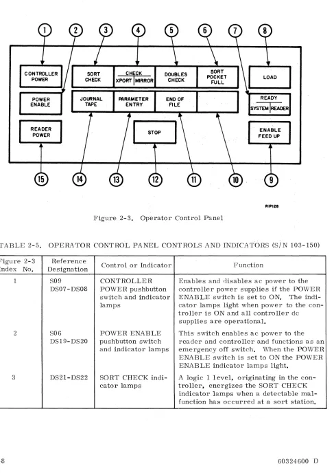
Figure 2~3. Operator Control Panel
ENABLE
FEED UP
, 9
RIPI28
TABLE
2~5;
OPERATOR CONTROL PANEL CONTROLS AND INDICATCmS (SIN103~150)
Figure 2~3
Index No.
1 2 3 2~8 Reference Designation S09 DS07~DS08 S06 DS19-DS20 DS21-DS22
Controlo.r Indicator
CONTROLLER POWER pushbutton switch and indicator lamps
POWER ENABLE pushbutton switch and indicator lamps
SORT CHECK indi~
cator lamps
Function
Enables and disables ac power to the controller power supplies if the POWER
ENABLE switch is set to ON. The indi~
cator lamps light when power to the con~
troller is ON and all controller dc supplies are operational.
This switch enables ac power to the reader and controller and functions as an emergency off switch. When the POWER ENABLE switch is set to ON the POWER ENABLE indicator lamps light.
A logic 1 level, originating in the con~
troller, energizes the SORT CHECK
indicator lamps when a detectable mal~
function has occurred at a sort station.
c
c
[,.
[
[-~, ~0"·
".',ft."
~I
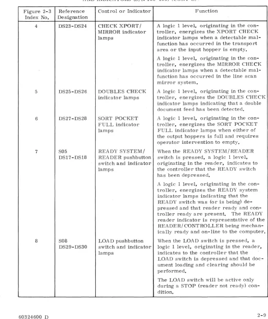
Figure 2-3 Index No.
4
5
6
7
8
60324600 D
TABLE 2-5. OPERATOR CONTROL PANEL CONTROLS
AND INDICATORS (S/N 103-150) (CONT'D) ..
Reference Designation DS23-DS24 DS25-DS26 DS27-DS28 S05 DS17-DS18 S08 DS29-DS30
Control or Indicator
CHECK XPORT / MIRROR indicator lamps
DOUBLES CHECK indicator lamps
SORT POCKET FULL indicator lamps
REA DY SYSTEM /
REA DER pushbutton
switch and indicator lamps
LOA D pushbutton switch and indicator lamps
Function
A logic 1 level, originating in the
con-troller, energizes the XPORT CHECK indicator lamps when a detectable mal-function has occurred in the transport area or the input hopper is empty.
A logic 1 level, originating in the
con-troller, energizes the MIRROR CHECK indicator lamps when a detectable mal-function has occurred in the line scan mirror system.
A logic 1 level, originating in the
con-troller, energizes the DOUBLES CHECK indicator lamps indicating that a double document feed has been detected.
A logic 1 level, originating in the
con-troller, energizes the SORT POCKET FULL indicator lamps when either of the output hoppers is full and requires operator intervention to empty.
When the READY SYSTEM/READER
switch is pressed, a logic 1 level, originating in the reader, indicates to the controller that the READY switch has been depressed.
A logic 1 level, originating in the
con-troller, energizes the REA DY system
indicator lamps indicating that the
READY switch was (or is being) de-pressed and that reader ready and
con-troller ready are present. The READY
reader indicator is representative of the
READER/ CONTROLLER being mechan-ically ready and on-line to the computer.
When the LOAD switch is pressed, a logic 1 level, originating in the reader, indicates to the controller that the LOAD switch is depressed and that doc-ument loading and clearing should be performed.
The LOA D switch will be active only during a STOP (reader not ready) con-dition.
[image:25.613.27.548.124.745.2]TABLE 2-5. OPERATOR CONTROL PANEL CONTROLS
AND INDICATORS (SIN 103-150) (CONT'D)
Figure 2-3 Reference
Index No. D~signation
8 (cont'd) 2-10 9 10 11 12 S04 DS05-DS06 DS15-DS16 S03 DS13-DS14 S07 DS03-DS04
Control or Indicator
ENABLE FEED UP pushbutton switch and indicator lamps
Spare
Fun~tion
. A logic I level, originating in the
con-troller, energizes the LOAD indicator lamps. The LOAD indicator lamps will light with depression of the LOAD switch and will remain on until a document is at ready position.
Enables and disables the feedup table drive clutch. The indicator lamps light when the feedup table is enabled. Nor-mally, feedup table is disabled for docu-ment loading.
Not used.
END OF FILE pllsh- When the END OF FILE switch is
press-button switch and ed, a logic 1 level originates in the
indicator lamps reader indicating to the controller that
the end of file switch is depressed. A logic 1 level originating in the controller, energizes the END OF FILE indicator lamps. Pressing end of file causes the end of file indicator and end of file status to toggle, ON or OFF, based on its previous condition. END OF FILE will also clear on clear controller or master clear. The END OF FILE indicator lamps will reflect the condition of END OF FILE status to the computer and will be active only during a STOP condition.
STOP pushbutton switch and indicator lamps
When the STOP switch is pressed, a logic 1 level originates in the reader, indicating to the controller that the STOP switch is depressed.
A logic 1 level, originating in the
con-troller, energizes the STOP indicator lamps when the reader has lost its mechanical or functional ready condition or the STOP switch has been depressed. The STOP indicator is representative of a "reader not ready" status to the com-puter, and "reader off line" to the oper-ator.
60324600 D
[image:26.612.60.573.80.757.2]r--:."
~
~\
L '
r'
L
[
[
('
"[,
[\
, /D
D
D
L\
": ",./Figure 2-3 Index No.
13
14
15
60324600 D
TABLE 2-5. OPERATORS CONTROL PANEL CONTROLS
AND INDICATORS (SIN 103-150) (CONT'D)
Reference Designation
S10
DSll-DSI2
S02
DS09-DSI0
SOl
DS01-DS02
Control or Indicator
PARAMETER
ENTRY pushbutton switch and indicator lamps
JOURNAL TAPE
pushbutton switch and indicator lamps
(option only)
READER POWER pushbutton switch and indicator lamps
Function
When the PARAMETER ENTRY switch is pressed a logic 1 level originates
in the reader enabling PARAMETER
ENTRY. Signal will cause controller to generate a parameter ready only condi-tion.
A logic 1 level, originating in the
con-troller, energizes the PA RAMETER
ENTRY indicator lamps. Indicator lamps light when switch is depressed and controller is holding parameter ready only condition.
Enables and disables journal tape option. Lights indicator lamps when pressed.
Enables and disables reader ac power if
the POWER ENABLE and CONTROLLER POWER switches are set to ON. The indicator lamps light when power to the reader is on and all dc supplies are oper-ational.
[image:27.612.25.552.135.762.2]Figure 2-4. Index No.
1
2
3
4
2-12
DOUBLES DOUBLES ADJUST INDICATOR.
e
PAPER GUIDE WIDTH ADJUST
e
THINNER PAPER DOCUMENT THICKNESS ADJUST
e
RIQOOIA
Figure 2-4. Document Adjustment Panel
TABLE 2-6. DOCUMENT ADJUSTMENT PANEL
Reference
Control or Indicator Function
Designation
R01 DOUBLES ADJUST Adjusts doubles threshold level which is
potentiometer indicated by the DOUBLES INDICATOR.
CR01 DOUBLES INDICA- Lights when doubles are detected.
TOR
SOl PAPER GUIDE Adjusts input'hopper and edger guide
WIDTH ADJUST plates.
switch
COl DOCUMENT Controls position of brushback roller
THICKNESS which is adjusted so that only one
docu-ADJUST ment will be fed at a time.
control
60324600 D
()
c
c
c
c
c
c
c
c
()
[image:28.612.58.606.49.735.2]c
D
F"',
L /
r"\
!
b-/
[image:29.612.27.546.123.761.2]TABLE 2~7. JOURNAL TAPE CONTROL PANEL (SEE FIGURE 2~5)
Figure 2~5 Reference
Control or Indicator Function
Index No. Designation
1 Potentiomete r MOTOR CONTROL Controls the torque of journal tape
motor.
2 Switch ACtoggle Applies ac power to journal tape motor.
Step
1
MOTOR
CONTROL
AC
RJP082
Figure 2~5. Journal Tape Control Panel
TABLE 2-:-8. JOURNAL TAPE (OPTION) LOADING PROCEDURE
Equipment
Operator Control Panel
Procedure
NOTE
If journal tape is less than 3 inches
wide, a leader at least 3 inches wide must be spliced to the tape before loading is attempted. Splice may be
either butt or overlapped using a non~
bleed, clear transparent tape on the
nonread side of the journal tape. If
an overlap splice is used, the leader should be spliced to the nonread side
of the journal tape. A 1/8 inch
(3.175 mm) maximum overlap is permitted. (Refer to Pub. No. 60216102. )
Step
2
3
4
5
2-14
TABLE 2-8. JOURNAL TAPE (OPTION) LOADING PROCEDURE (CONT'D)
Equipment
Journal tape option
Operator Control Panel
Journal tape option
Takeup assembly
Procedure
Refer to Table 2-1 for power turn-on procedure.
On journal tape assembly, lift and fasten read a~ea cover.
Push mechanical release arm pawl and arm latch to release both roller arms as shown in Figure 2-6. Adjust spooler assembly roll retainer and lower take-up spindle.
Plac~ tape roll on input spindle and thread through tape centering guides to reader conveyor as shown in Figure 2-6.
Press JOURNAL TAPE pushbutton. JOURNAL TAPE indicator lights.
Press LOAD pushbutton indicator.
Tape moves to read area and stops.
Press READY pushbutton indicator. READY lights.
Tape is picked off vacuum belt by take-up fingers and
guided through take-up spindle. When tape is approximately 3 inches past take-up spindle, tape is automatically wound around spindle.
When tape has been read, lift roll retainer and remove roll
of tape using slight counterclockwise twist.
60324600 D
u
o
o
c
c
c
c
c
[image:30.612.61.583.109.771.2]-,
~
O"l
o
w
I',;)
,j::. O"l
o o
lJ
I',;)
I
>-'
CJl
----
I',;)I
>-'
O"l
~~
,.,
.~
TAKE-UP
SPINDLE~
DRIVE BELT .. /
DRIVE MOTOR
~
~
ROLLER GUIDE POS ITION SWITCH
~ ,~
,..
'1
~MIRROR
E~OER IL~
r-~~JlI
II
,
II
lI-cIt
I IC:? '
II
r-_J
----l.k----i~
JJ
TAKE-UP ARM -RELEASE SWITCH /'
RELEASE ARM MECHANICAL ; '
LATCH ' TAKE-UP
I,
TAKE-UP FINGERS
ROLLER I I INPUT ROLLER
READER CONVEYOR VACUUM BELT
FRONT VIEW
~
Figure 2-6. Journal Tape Option
~
,
~,..,
"' -f
RIT099
o
\ j
MECHANIAL RELEASE ARM PAWL
[image:31.801.50.705.20.538.2]()
(J
o
(c~.·"
\ ,
"-'",
~;il(~'"
I ' \~
c
Ie
c
c
o
r-~
~:
D
<.- '
SECTION 3
PROGRAMMING
INTRODUCTION
This section contains programming information to enable reading and processing of printed pages and documents under control of a 1700 Computer. Function codes issued by the com-puter condition the controller to perform certain operations in controlling the reader. Status codes generated by the controller enable the computer to monitor certain conditions in the controller and the reader.
Two functions, Coupler mode and A utoload Control mode,require only that power be applied to the reader and the controller. For performance of any other functions the reader and controller must be Ready and the controller must be Not Busy.
The controller provides two levels of status. System status covers general conditions in the controller and the reader. Transport status is reserved for specific faults which occur in
the transport system of the reader; for example, mirror faults. Current position of the
line scanning mirror is included in the Transport status. Table 3-1 contains a list of Function and Status Codes and Table 3-2 contains a list of Data Transfer Words.
I/O COMMUNICATION
Communication between the 1700 Computer and the Buffer Controller is handled through the 1700's A/Q Channel. This I/O channel is directly linked to the A and Q Registers of the 1700 and to the Coupler of the Buffer Controller. The Basic Q register format is shown
in Figure 3-1.
15 II
I
w=o, .,
I
60324600 D
10
I
n
07 06 04 03 00
EQUIP = A . . DIRECTOR
.,
..
I
I DIRECTOR FUNCTIONEQUIP CODE CONVERTER CODE
R3U004
Figure 3-1. Q Register Format
CONVERTER CODE
For this system, Converter Code (W) O.
EQUIPMENT CODE
For this system, Equipment is A.
Director 3-2 1 2 3 4 :5 6 8 9 1 2
TABLE 3-1. FUNCTION AND STATUS CODES
Title Use
Function Codes
NOTE
The coupler is the portion of the con-troller which actually interfaces with the 1700 Computer.
Coupler mode Provides internal control to the coupler only, and permits
selection arid clearing of interrupts.
Parameter mode Determines the transfer format of read data, controls the
scan height, controls transmission of Font/Field and Con-trol parameter tables, and indicates the number of words in a given parameter table.
Positioning mode Determines the page advance parameters and provides a
mirror count representing the coordinate to which the line scanning mirror is to be moved.
Mechanical A ction mode
Read mode
Line locate mode
A utoload data mode
A utoload control mode
Includes :-;elected mechanical actions: Zero Mirror, Sort to pocket 1, Sort to pocket 2, and Mark Document.
Contains the initial and final mirror coordinates for the line to be read.
Contains the initial and final mirror coordinates for a line that is to be located and centered in the read area.
Consists of a block of up to 4096 words comprising the resident software to be loaded into the controller memory.
Given just prior to loading the resident software program into the controller, this function also permits selection and clearing of interrupts.
Status Codes
System status Covers general conditions in the controller and the reader.
Transport status Indicates line scanning mirror position and identifies specific faults in the transport system of the reader.
60324600 D
r"\
... ..1/
D
Table Identifier Hex.
D=O, WRITE
ID 1
ID 2
ID 4
ID 5
ID 6
ID 7
ID 8
ID 9
ID A
ID B
ID C
ID D
ID E
ID F
60324600 D
TABLE 3-2. DATA TRANSFER WORDS
Word
Used to send over the Font/ Field or the Control Table Word or OLCC (ID 8)
Font/Field Word
Font Word
Initial Field Coordinate Word (IFC)
Terminal Field Coordinate Word (TFC)
Video Word
Line Width Word
Handprint Font Select Word
Character Correction Word
Control Word
End of Line Word
Cancel Character Word
Delete Line Word
Blank Line Word
Mirror Image Word
Rescan Word
Document Ready Advance Word
[image:35.612.41.551.109.767.2]TABLE 3-2. DATA TRANSFER WORDS (CONT'D)
D=O, READ
CHARACTER DATA CODES
14 08 06 00
ASSEMBLED DATA
I
1 \ I~ READ WORD
..
, 1 1 \ 2~ READ WORD.
,I
A REGISTERI
I
ASCII CHARACTER BITS15 07 06 00
CHARACTER DATA
I
UNASSIGNED 126 - - - 201 A REGISTER\ ... ,
L
ASCII CHARACTER BITS13 08 06 00
CHARACTER DATA
1
I
I
126 ___ ~ ______ 20
I
A REGISTERAND SERVO DATA* SERVO DATA
\
.
,L
ASCII CHARACTER BITS13 12 II 08 06 00
CHARACTER DATA
1 1 1 1
,I
126 _ - - - _ 201AND CHARACTER VOLTAGE* A REGISTER
\'
.
\ ... ,I
L
ASCII CHARACTER BITS CHARACTER VOLTAGE BOTTOMLESS DATA TOPLESS DATA* USED FOR MAINTENANCE PURPOSES ONLY. R3UOO5
3-4 60324600 .b
u
,()
o
o
c
c
c
o
,
'<i!..Ji1
c
c
c
c
c
b
o
o
[image:36.612.50.558.55.580.2]C
.. ··~: ,c
r
l
b
D
C;,
DATA TRANSFER
To transfer data, all bits of the Director must equal zero, and art accompanying Read
signal or Write signal will specify the direction of data flow. Write data consists of table
words for the control of Font/Field or Control Tables or OLCC (see Table 3-2). A Direc-tor 2 (Parameter mode) function immediately precedes the transmission of Write data, and a Parameter Command within this function indicates how the new table words will be entered. For example, in some cases the previous table may be cleared and a new one entered, or the new table words may replace corresponding words in an existing font / field or control table. The uppermost 6 bits of the Director 2 function contain a binary count equal to the number of table words to be transmitted to the controller.
On a Read data, the first word of the data block will consist of a binary number defining the length of the data block being transferred. Table 3- 2 contains a listing of the formats the
READ DATA can be received in. The formats are selected in the Director 2 (PA RAMETER
MODE) function.
Read data is normally transmitted in the "assembled" format, with two 7-bit characters per
16-bit word; however, single-character transmission can be selected if desired. The data
will be transmitted in the lower byte, and the upper byte of the word will be clear. For maintenance purposes, two additional Read modes are available in which additional
infor-mation is transmitted in the upper byte. (See Table 3- 2 and Director 2, function bits 5 and
6.) Table 3- 3 lists the hexadecimal character codes used in this equipment for A NSI upper case and lower case characters.
DIRECTOR FUNCTIONS
INTRODUCTION
Six different System Control director functions are defined by bits 0 through 3 of the Q
register, accompanied by a Write signal. The "specific" functions in each of these cate-gories are defined by bits of the A register, and are acted on or stored by the Controller.
Coupler Mode (D= 1)
Functions include Clear Controller; Clear Interrupt; Data Interrupt Request; End of
Operation Interrupt Request (EOP), and Alarm Interrupt requests. The Coupler will accept
all Coupler Mode functions, regardless of the state of Ready or Busy if power is on. Refer
to Figure 3- 2 for Coupler Mode Word Format.
Clear Controller
Bit 0 clears all interrupt requests, errors, and other clearable coupler logic, as well as providing for programmed clearing of the Controlware. This bit will be subordinate to all interrupt request bits after clearing interrupts and interrupt requests.
Clear Interrupt
Bit 1 clears all interrupt requests and responses. This bit will terminate data transfers between the buffer controller and the 1700 system. This bit will be subordinate to all interrupt request bits after clearing interrupts and interrupt requests.
TABLE 3-3. CHARACTER CROSS REFERENCE CHART
Hex. OCR TTY Hex. OCR TTY He~. OCR TTY
20 Space Space 36 b 6 4C L L
21 6
,
37 7 1 4D M M22
"
"
"
38 8 8 4E N N23
•
# 39 OJ 9 4F 0 024 $ S 3A :
.
50 P P25 %
%
3B ;.
,
51 Q Q26 & 8 3C i't Y . iUnusec 52 R R
27 ~
"
3D=
-
-
53 S S28 { ( 3E f Ii
t
54 T T29 } ) 3F ? ? 55 U U
2A It lie
*
40 Reject IUnused 56 V V2B +
+
41 A A 57 W W2C
,
I 42 B B 58 X X2D
-
-
43 C C 59 Y Y2E
.
.
44 D D 5A Z Z2F /
/
45 E E 5B IUnused Unused30 0 0 46 F F 5C
I
<31 1 1 47 G G 5D J. I
+-32 2 2 48 H H 5E
-
Unused33 3 3 49 I I 5F t (Ci)
34 4 4 4A J J 60 Unused Unused
35 5 5 4B K K
ANSI Lower Case Ch3.racter Set
Hex. OCR Hex. OCR Hex. OCR
61
a
6A j 73s
62 b 6B k 74 t
63
c
6C 1 75 u64 d 6D m 76
v
65 e 6E n 77 w
66 f 6F 0 78 x
67 9 70 P 79 Y
68 h 71 q 7A
z
69 i 72 r
. -
--Control Character Code FF Indicates Field Separator
3-6 60324600 D
u
()
c
c
c
c
c
,,-c
C
l:
C
C
(j
C
C'·
.i
D
c
[)
l /
c
D
15 II 10 7 6 4 3 0
W;O E=A
~
0= I Q REGISTER15 5
UNASSIGNED A REGISTER
INTERRUPTS INTERRUPT REQUEST END OF OPERATION INTERRUPT REQUEST ALARM INTERRUPT REQUEST
R3U006
Figure 3-2. Coupler Mode Format
Data Interrupt Request
Bit 2 selects a Data Interrupt Request, causing an interrupt response to be generated when a data transfer is ready. The interrupt response is cleared by the Reply to data transfer. Both the interrupt request and response are cleared by either the Clear Controller, Clear Interrupt, or Master Clear signals.
End of Operation Interrupt Request
Bit 3 selects the End of Operation Interrupt Request. An End of Operation is defined as the completion of a directed operation. Both the interrupt request and response are cleared by either the Clear Controller, Clear Interrupt, or Master Clear signals.
Alarm Interrupt Request
Bit 4 selects the Alarm Interrupt Request. For this equipment, an alarm is defined as the occurrence of one of the following conditions: Not Ready, Lost Data, Transport Status Fault, Line Locate Failure, Autoload Required, Document No Sort, Data Skewed, or Docu-ment Length Fault.
NOTE
Feeder Doubles, Document Runout, Sort Check Fault, and Sort Pocket Full cause Ready to drop
(as well as lighting the corresponding indicator) resulting in an Ahtrm condition.
Both the interrupt request and response are cleared by either the Clear Controller, Clear Interrupt, or Master Clear signals.
Unassigned
Bits 5 through 15 are unassigned.
[image:39.612.92.514.85.347.2]Parameter Mode (D=2)
Functions include Clear, Data, End of Operation and Alarm Interrupt Requests, Character mode, Scan 2 mode, Parameter Command and Parameter 'Nord Count. The Controller will accept Parameter Mode functions while Ready and Not Busy. On acceptance, the Coupler will go Busy and remain Busy until transmission of the parameter word(s) has been com-pleted. All Parameter Mode functions must be selected prior to initiation of a Read Mode
function (D=5). Refer to Figure 3-3 for Parameter Mode Format.
15 II 10 7 6 4 3 0
'--_ _ W_=_O _ _ _ '--_ _ E_=_A _ _ . .
~;!,\._w.li~_.
_ _ 0_=_2_---11 Q REGISTER15 10 9 8
COUNT
7 6 5 4 3 2 0
,.
I
I
A REGISTERl1~
L
LUNASSIGNED CLEAR INTERRUPT DATA INTERRUPT REQUEST. END OF OPERATION INTERRUPT REQUEST ALARM INTERRUPT REQiJEST
O=PACKED CHARACTER MODE CHARACTER MODE - - - ( I = SERVO DATA MODE
2=CHARAcrER ·DAlAMODE SCAN 2 MODE
PARAMETER COMMAND
3= CHARACTER PEAK VOLTAGE MODE '----PARAMETER WORD COUNT
00= CLEAR F/F TABLE 01 = CLEAR AND ENTER
CONTROL TABLE 02= ENTER I7F TABLE
03= REPLACE CONTROL TABLE R3U007
Figure 3-3. Parameter Mode Format
Clear Interrupt (Refer to Coupler Mode).
Data Interrupt Request (Refer to Coupler Mode).
End of Operation Interrupt Request (Refer to Coupler Mode).
Alarm Interrupt Request (Refer to Coupler Mode).
Character Mode
Bits 5 and 6 direct the Controll~r to transmit read characters as follows (see also Table 3-2):
3-8
00 - Assembled Data Mode
The Controller transmits the first read character in the most significant half of the data word, and the second read character in the least significant half of the data word.
60324600 D
u
o
o
o
c
c
o
c
o
o
o
c
o
c
o
~ ...
[image:40.612.62.579.159.613.2],.\
.JJ
-"'"' \
'111\
I
-..,/
10 - Character Data Mode
The Controller transmits read characters singly in the least significant half of the data word, and the most significant half of the data word is set to zero.
NOTE
The following modes of data transfer are used for maintenance purposes only.
01 - Character and Servo Data Mode
The Controller transmits read characters singly in the least significant half of the data word and the most significant half of the data word contains the servo count for that character. (Servo count indicates how well the character is registered with the center of the optic s. )
11 - Character Data and Character Peak Voltage Mode
Scan Mode
The Controller transmits read characters singly in the least significant half of the data word. and the most significant half of the data word equals the stored character peak voltage for that character plus an indication of data extending
beyond the optical limits of the Reader. (Character peak voltage indicates the
degree of correlation with the character matrix. )
Bit 7 controls the height of the scan area on the page. When bit 7 is clear, the Reader will
scan 3 characters high and when bit 7 is set, the Reader will scan 2 characters high. If the
Reader is equipped with the 6 lines linch option, selection of bit 7 enables reading of 6 lines/ inch data.
Parameter Command
Bits 8 and 9 direct the Controller to Input font, field, and control parameters as follows:
NOTE
Table 3-2 contains a listing of the pa-rameter command words, with their table identifiers.
00 - Clea r Font / Field Selection
The Controller will stop coordinate testing and font selections for a previously entered font/field table.
01 - Clear and Enter Control Selection
The Controller will clear a previously entered control table and prepare to enter
a new control table of (Parameter Word Count) words. A Parameter Word Count
equal to zero acts as a Clear Control Table Function. 10 - Enter Font/Field Table
The Controller will prepare for input of font/field words that will define initial and terminal coordinates of a read, video parameters, and the font or ANSI