On-site Engineering Information Systems (EIS) for
Building and Construction Projects
Koorosh Gharehbaghi
School of Property, Construction and Project Management, RMIT University, Australia
Copyright © 2016 by authors, all rights reserved. Authors agree that this article remains permanently open access under the terms of the Creative Commons Attribution License 4.0 International License
Abstract
The expectation of economic andperformance-related benefits has led to the rapid penetration of computer-based Information Systems such as on-site Engineering Information Systems (EIS) into all facets of a Building and Construction projects and their activities. While the benefits range from increased productivity to reduced working-capital needs; key advantages also includes the capability to increase production and services. These explicit key advantages are in contrast to the benefits of different systems such as Building Information Modeling (BIM). While Building Information Modeling (BIM) investigates general and broad aspects of information, the proposed Engineering Information Systems (EIS) specifically deals with the complex data and its related predicament. Engineering Information Systems (EIS) not only provides increased productivity through better operational process, but also enhances project environment. This paper will introduce on-site Engineering Information Systems (EIS) for building and construction projects to improve productivity which in-turn will increase project’s production and services level. In doing so this paper will also incorporates system methodology approach as a part of Engineering Information Systems (EIS) development. The key findings of this research indicate the importance of the inclusion of on-site Engineering Information Systems (EIS) to assist with the administrating of large raw data generated during the design and construction of various building projects.
Keywords
Engineering Information Systems (EIS), Building Information Modeling (BIM), Building and Construction Projects, EIS Interface and System Parameters1. Introduction
In Building and Construction projects, tasks typically tend to become more routine at the clerical and supervisory levels, but more challenging and demanding at the senior levels. However, computers also permit solution of problems they
cannot be attacked manually, with a consequent increase in job satisfaction at the relevant levels. Thus the utilization of on-site Engineering Information Systems (EIS) is becoming more and more common. The most important issues in an on-site Engineering Information Systems (EIS) are the general aims and the output of the system. Furthermore, the Engineering Information Systems (EIS) derivesto a series of key outcomes including improved operational process and increased project productivity. These key outcomes are fundamental aspects of on-site Engineering Information Systems (EIS). Moreover, the most important aim of any on-site Engineering Information Systems (EIS) would be the superior project strategy through improved project productivity [1, 2].
Furthermore, various different outcomes of the on-site EIS will include:-
Complete Project (Confidential) Information database that will include all the client’s contact numbers, personal information and histories. All of the relevant negotiations and documents will also be integrated within the EIS.
Detailed Project Outline, which include information such as costing agreements; drawings of related plans including underground sewerage, electricity, storm runoff, easements, caveats and other factors which can influence the satisfactory completion of the project. Detailed specifications on machinery to be used, materials to be ordered and information on how to purchase such materials and machinery would also need to be included within the EIS.
Other relevant Building and Construction Information, including list of companies (and their contact information) which are taking part in the project need to be incorporated.
Payroll, including all the payroll documentation including pay slips and payroll queries, job application forms are also integrated within the EIS.
All the Correspondence including messages, notices, progress claims and minor quality assurance control information are also featured within the EIS.
Digital Information, including all the information which is unable to be stored as hard copies are stored as digital formats. This information includes drawings, and photographs of scanned images or databases of significant information.
Miscellaneous Information. Miscellaneous information which is not part of the other outcomes is incorporated here.
[image:2.595.312.561.177.316.2]Effective EIS not only exceed the above outcomes but also deals with these effects at the lowest (data) level. This ensures that the raw data is consistently monitored which in-turn will enhance the project production and outputs [16]. Ultimately in achieving all of the above outcomes, the EIS need to consider and incorporate a holistic system approach, which is shown in Figure1 below.
Figure 1. Building and Construction EIS preface.
To further comprehend the EIS preface, a less intensive system methodology such as BIM needs to be investigated. This step is important in determining the significance of EIS inclusion for various building and construction projects.
2. Building Information Modeling (BIM)
As Schreyer (2016) accurately argues, BIM has become great tool allowing reduced construction cost and accelerating construction projects. According to Stackowiak et at. (2015) Building information modeling (BIM) is a process involving the generation and management of digital representations of physical and functional characteristics of places. Furthermore Deutsch (2015) reiterates that BIMcould include are internal files which usually can be exchanged or networked to support decision-making about a place. In other words any software or instruments which could assist in managing and maintaining buildings could fall under the Building Information Modeling (BIM). These instruments range from in-house to commercial software such as Revit and so on [19]. Figure 2 provides schematics of BIM and project lifecycle.
Figure 2. Schematics of BIM and project life cycle [15].
As Levy (2012) correctly argued that BIM has the potential to avoid mistakes if careful planning is utilized at the earliest stage of the project. The importance of this early planning is vital for any project and thus any necessary data and information needs to be carefully integrated. This is the most risk prone stage of BIM, and if all the necessary information is not inputted the overall effectiveness of BIM significantly reduces. While BIM investigates general and broad aspects of information at the planning stage, the EIS specifically deals with the complex data and its related predicament. Thus the main shortfall of BIM is its lack of ability to deal with raw data at the planning stage, which is the main advantage of EIS.
3. Engineering Information Systems
(EIS)
Commonly in developing and designing an appropriate Engineering Information Systems (EIS), the following system parameters need to be carefully considered [2, 3, 4]: Decentralization or Centralization. Many observers
similarly condemn information system as being instruments of centralization - especially in the decision making area, for example on-site information retrieval, access and modification [19][20][21]. However, it is obvious that a computer’s information reporting can support any organizational structure, depending on how the information flow is designed. Thus the net effect depends on the organization’s administration style. Decision Making. The introduction of computer
[image:2.595.64.293.330.567.2]to decrease rigidity and inflexibility in the decision area. Admittedly, including flexibility does usually require extra design creatively and effort and, in the absence of such an effort, it is likely that a more rigid system would result.
User satisfaction. There is no inherent characteristic of computer-based information systems, which increases either satisfaction or dissatisfaction for the system’s users. Considerable criticism has been made of the approach taken by designers who focus attention on the technical and financial aspects of a project to the detriment of the human interface design.
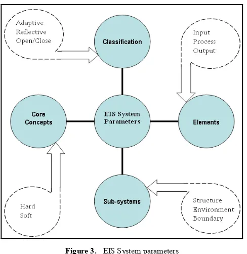
[image:3.595.57.301.250.501.2]Figure 3 below summarizes the EIS system parameters and their relationship [5].
Figure 3. EIS System parameters
A primary objective, when designing the appropriate EIS system parameters is to provide write and retrieval efficiency, since access to data on secondary storage is slow in comparison with other computer functions. The factors which affect the design of the EIS system parameters include [5, 6]:-
Volatility. This term refers to the number of additions, deletions, and/or changes to the records in a file. Activity. The amount of activity is the proportion of
records which has to be processed in any given computer run; a payroll file has a high activity as each record is usually processed, often on a daily basis. The manner in which the file is organized (arranged) should assist in locating a particular record as quickly as possible. The activity ratio is the number of records processed compared to the total number of records in the file. This is also referred to as the ‘hit rate’. Size. If a file is very large it is sometimes desirable to
alter its organization and processing in certain ways to achieve retrieval efficiencies. For example, where each record in a file contains a large number of data items, it
may be desirable to maintain two files. One file - known as the ‘abridged file’ - contains the data items which change frequently (eg. invoice amounts, daily wages) and the other is a complete file of all data items. The abridged file is processed more frequently than the complete file, and is used to keep the latter up-to-date. This procedure conserves space in the computer main storage during processing and allows faster processing to be carried out.
Growth. The potential growth of the file must be considered, and planning must include arrangements as to how the anticipated growth in the size of the file is to be handled in the future. Many problems arise if not enough care is taken in planning the growth of a system to meet the increased information needs of an organization.
File medium available. One of the major areas for records management is the application of its standards to both the construction and control of relational databases. If structure is significant then clearly a database must be able to reproduce it.
Figure 4 below represent example of a typical Building and Construction project database-setup progression.
Figure 4. a typical Building and Construction project database-setup progression.
Moreover, there are also two types of File Organization
and Retrieval [7, 8, 9]:
1. Sequential Organization - Sequential file, is one in which contiguous records follow a predetermined usually key sequence:
[image:3.595.316.550.356.601.2] Direct Access, is defined as the ability to go directly to any wanted records. Two methods for achieving direct access are:-
Addressing, is establishing a relationship between the records’ key and the record’s actual address. Indexing, are pointers to keys held on the data file,
and the therefore provides a system which allows both sequential and direct access to the data file, without the restrictions of self or partial addressing.
2. Random Organization - Random file, is one in which there is no simple relationship between contiguous records. The method of organization is based on a computed relationship between the records key and the location at which the record is stored. Methods available for generating an address from the record key include: Division; Extraction; Folding; and Squaring. Considering system key outcomes and parameters together with detailed setup progress are all fundamental aspects during the design stage of EIS for building and construction projects.
4. Designing EIS for the Building and
Construction Projects
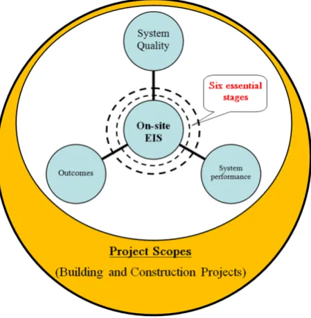
[image:4.595.67.292.469.699.2]Once careful EIS analysis and requirements definition have been carried out, the design of EIS for building and construction projects can be initiated. The design initiation of EIS for building and construction projects includes the incorporation of its essential stages, which is shown in Figure 5 below.
Figure 5. Building and Construction EIS culmination. As it can be noticed, EIS’s core essential stages are at the center of the system for building and construction projects includes. These six essential stages are [10, 11, 12]:
i). Develop the new Logical system. The new logical system is designed which includes all the user’s logical requirements by means of the data flow diagrams (or other techniques), the data dictionary, and the supporting documentation - the network of logical steps required to transform the input data to the output reports, documents, and file data. There are three steps to develop new logical system: Developing the new logical data file dictionary; Designing the files; and updating the data dictionary. Developing the New Logical Flow Diagram. The new
requirements can be summarized as: Place this system on the computer, Produce listings of orders and back orders. Designing System Files. Designing the system files for
the new EIS requires grouping of the classes, objects and entities for which the system needs to maintain or store information. In most cases the individual records need to be identified either individually (eg. master file records), or as a member of a group (eg. transaction file records). Examples of group membership are:
All the order transactions in a certain batch, All the orders for a certain product,
All the orders from a certain customer for a certain product.
A record is identified by the unique record key which is composed of one or more data items on the record: The Data Dictionary. The data dictionary defined for
the current system needs considerable expansion to include the additional data elements, new files and records, and new data flows that may have been included on the new logical DFD.
ii). Implementation Planning [13].
The need for an implementation Plan. A care full and well-devised plan for the implementation of a new system needs to be made before finally setting on the physical design.
Changeover Approaches. The changeover approaches which generally form the basis for implementation plan are:-
Parallel running of new and old system, Phase in new system and phase out old system, Pilot study on new system.
Start up new system and stop old system. iii). Input/Output Media Selection.
Input Media.
Batched input. This is probably the most commonly used method of input. It affords good opportunity to verify and control input, but its disadvantages is that it isolates the users from data preparation and introduces time delays between data entry, data processing and output.
Location of Input Devices. Input devices may be located centrally or decentralized to the user site where the data originates.
Output Media. The primary means of output available to the systems designer are printers, VDU’s, voices, and Microfilm/Microfiche.
iv). Developing the Physical System [14].
Input. The logical design results in draft formats for the input, such as documents or screen layout.
Output. The draft outputs must be converted to their final form, be it computer listings, screen layouts, or partly pre-printed documents.
Files. A proposed set of files with the record key/s and contents will have been documented as a result of the logical design. They now have to be:
Confirmed or altered in accordance with the capabilities of the target computer environment, Fully documented.
Processing. This stage of the design involves packaging the bubble procedures into programs, and specifying the system security, control, and back-up provisions in the light of the chosen hardware, file organization, input, and output.
v). Documentation.
Report Layouts. The content of all reports are determined during the logical design.
Screen Layout. The designer must precisely define the screen contents for the programmers, usually using a worksheet similar to the report worksheet, but reflecting the size of a screen.
Program Specifications. To design and code each program the programmer needs a description of the program, which should contain the program number, program name, overview description, system flowchart, files required, input and output layouts where relevant, and processing requirements.
System specification. The system specification document outlines the whole system at a broad level, and consists of a logical data flow diagram, system flowchart, input documents, output documents, and general description, controls and security, and
implementation plans.
User Instructions. It is vital to have a set of computer-use instructions wherever a user makes contact with the system, as in decentralized data entry. vi). Estimating Run Time.
It is frequently necessary to estimate the time a system will take to run on a particular computer:-
Design Estimation. Before programming, a system run-time estimate can be made from knowledge of the necessary input-output activity of the individual programs, by calculating the run time for each program and hence, by addition, the system run time.
Pilot-run Estimation. Frequently, run times need to be estimated based on the results of a pilot run or benchmark test.
Time-estimation Issues. Multiprogramming. Coding efficiency. Location of computer file. Performance data.
Designing and developing EIS for building and construction projects possess challenging system progression and application. However, incorporating the six essential stages ensures an effective system application for building and construction projects. As it can be noticed the inclusion of EIS to assist with administrating large raw data generated during the design and construction of various building projects is of an essential importance and advantage.
5. Comparison of BIM and EIS
As Already discussed the main shortfall of BIM is its lack of ability to deal with raw data at the planning stage, which is the main advantage of EIS. Although this is the main difference, it is not the complete list of differentiation. to appreciate the significance of EIS for Building and Construction projects a more differentiation analysis is required. This comparison is provided via the following table:
Table 1. BIM and EIS Comparison
System Advantages Disadvantages Differentiation
BIM
More utilized for planning and managing risks.
No traditional user training/expertise is required.
Intermediate System Application. Uncomplicated Modeling sequence.
Obscure integration if too many
operational alterations. Generally utilized for simple and unsophisticated Systems.
EIS
Excellent for Data schematics, including complex data.
Advanced System Application. Flexible Integration.
Extensive user training and expertise is required.
Problematical Modeling sequence.
Ideal for complex and
As it can be noticed while BIM is suitable for unsophisticated Systems, EIS is more appropriate for convoluted data structures. Although BIM will be appropriate for traditional Building and Construction projects, any projects which require extensive System Engineering components, need to in-cooperate EIS as the basis of their core System approach. Accordingly for more complex projects which in turn have sophisticated System methodologies, the BIM component needs to possess an EIS element.
6. Conclusions
Engineering Information Systems (EIS) not only provides intensified productivity through improved operational process, but also heightens project environment. This paper has introduced the on-site Engineering Information Systems (EIS) for building and construction projects to improve productivity which in-turn will increase project production and services. As a part of the on-site Engineering Information Systems (EIS) development and design, this paper incorporated a system methodology approach. This system methodology approach is an integral aspect of effective and efficient on-site Engineering Information Systems (EIS).
The key findings of this research indicated the significant of the inclusion of on-site Engineering Information Systems (EIS) to aid with the administrating of large raw data generated during the design and construction of diverse building projects. As already discussed this paper dealt with the prologue of on-site EIS for building and construction projects, and therefore did not cover specific field studies or surveys. However this is suggested as a part of further recommendation for supplementary research and study. Therefore, to carefully emphasis the importance of EIS, field studies need to be carried out to address the system development, testing, and validation of the proposed EIS. This validates the EIS application and reviews/monitors any system specific needs or alterations.
REFERENCES
[1] D. Grau, E. Back, and R. Prince, Database expert planning system for on-site design strategies, Journal of Computing in Civil Engineering, Vol. 26, (2012).
[2] R. Wieringa, J. Gordijn, Advanced Information Systems Engineering 21st International Conference, (2009).
[3] D. Jin, Advances in Electronic Engineering, Communication and Management Vol. 1, (2011).
[4] J. Krogstie, A. Opdahl, and S. Brinkkemper, Conceptual
Modelling in Information Systems Engineering, Dordrecht : Springer, (2007).
[5] K. Gharehbaghi, “Infrastructure Asset Deterioration Modelling: A Mathematical Approach”, Proceedings of the Infrastructure Asset Engineering Conference (American Infrastructure Consortium), Los Angeles, California, United States, (2006).
[6] L. Hf and T. Chang, Web-based information management system for construction projects, Computer-aided civil and infrastructure engineering, vol. 17, (2002).
[7] R. Crotty, The Impact of Building Information Modelling Transforming Construction, Hoboken: Taylor and Francis, (2011).
[8] C. Peng, Y. Dong; and Q. Han, Communication and Control for Networked Complex Systems, Berlin, Heidelberg: Springer Berlin Heidelberg, (2015).
[9] F. Plummer, Project Engineering The Essential Toolbox for Young Engineers, Burlington: Elsevier Science, (2011). [10] C. Anumba, and X. Wang, Xiangyu, Mobile and Pervasive
Computing in Construction, Hoboken: Wiley, (2012). [11] G. Shen, P. Brandon, and A. Baldwin, Andrew, Collaborative
Construction Information Management, Hoboken: Taylor and Francis, (2009).
[12] W. Ulrich, Information Systems Transformation Architecture Driven Modernization Case Studies, Philip Newcomb, (2010).
[13] A. Wilinski, Fray, El, and J. Cham, Soft Computing in Computer and Information Science: Springer International Publishing, (2015).
[14] Dong, Zhai, Paul, Goodrum, and C. Haas, Carl, Relationship between automation and integration of construction information systems and labor productivity. Journal of Construction Engineering and Management, Vol. 135, (2009).
[15] BIM: Revolutionizing the building and construction industry: http://www.tekla.com/de/bim-forum-2013/bim.html
[16] Deutsch, Randy, BIM and integrated design: strategies for architectural practice, Wiley, (2011).
[17] Levy, Francois, BIM in small-scale sustainable design, Wiley, (2012).
[18] Schreyer, Alexander, Architectural design with SketchUp: 3D Modeling, Extensions, BIM, Rendering, Making, and Scripting, second edition, Wiley, (2016).
[19] Seidler, Douglas, Revit architecture 2016 for designer, Bloomsbury Publishing, (2016).
[20] Deutsch, Randy, Data-driven design and construction: 25 strategies for capturing, analyzing and applying building data, Wiley, (2015).
![Figure 2. Schematics of BIM and project life cycle [15].](https://thumb-us.123doks.com/thumbv2/123dok_us/8749307.891534/2.595.64.293.330.567/figure-schematics-bim-project-life-cycle.webp)