International Journal of Emerging Technology and Advanced Engineering
Website: www.ijetae.com (ISSN 2250-2459, Volume 2, Issue 9, September 2012)186
Comparative Study of Image Processing Techniques on
Geometrical Shape
Satish Misal
1, Shaikh Abdul Hannan
2, Santosh Lomte
31,2 Departement of Computer Science, Vivekanand College, Aurangabad
3
Dr. Seema Quadri, Institute of Engineering and management, Aurangabad
Abstract— Image plays very important role in human life Now a day it is one of the reliable sources of information. There were many image processing techniques have been proposed according to need. With the fast computers and signal processors available in the 2000s, [1]digital image processing has become the most common form of image processing, and is generally used because it is not only the most versatile method, but also the cheapest. Shape, color and texture are undoubtedly important visual features for image representation, there is still little understanding of how best to implement these attributes for image retrieval. This paper represents the various techniques of image processing & the comparative study of moment invariant with chain code technique on geometric shapes to extract feature based on shape and reason of image which produce better performance.
Keywords— Chain code, Image processing techniques, Moment invariant, Object recognition, Shape.
I. INTRODUCTION
Image processing techniques[2][3][4]can be categorized into Low level processing where we gives input as a image and we get output as image where as it includes noise removal and image sharpening. Middle level image processing where image as an input but output will be attribute processes like object recognition, segmentation. High level image processing includes input attributes and output will be understanding e.g. scene understanding, autonomous navigation.
Image enhancement: [5] [6] aims at improving the quality of image for better visualization. This paper presents three methods of image enhancement: - GHE, LHE and DSIHE that improve the visual quality of images. In this paper, we implement and examine the effect of above mentioned techniques based on objective and subjective image quality parameters (like PSNR, NAE, SC, AE and MOS) to measure the quality of gray scale enhanced images. A comparative analysis is also being carried out. For handling gray-level Images, Histogram Equalization (HE) methods (like GHE and LHE) tend to change the mean brightness of an image to middle level of the gray-level range limiting their appropriateness for contrast enhancement in consumer electronics.
The DSIHE methods seem to overcome this disadvantage as it tend to preserve both, the brightness and contrast enhancement, though at the cost of naturalness of the input image.
Pattern recognition: [7] it is "the act of taking in raw data and taking an action based on the category of the data". A complete pattern recognition system consists of a sensor that gathers the observations to be classified or described, a feature extraction mechanism that computes numeric or symbolic information from the observations, and a classification or description scheme that does the actual job of classifying or describing observations, relying on the extracted features.
Object recognition: Toward the development of an object recognition and positioning system, able to deal with arbitrary shaped objects in cluttered environments, [8][9][10] Introduce methods for checking the match of two arbitrary curves in 2D or surfaces in 3D, when each of these subobjects (i.e., regions) is in arbitrary position, and also show how to efficiently compute explicit expressions for the coordinate transformation which makes two
International Journal of Emerging Technology and Advanced Engineering
Website: www.ijetae.com (ISSN 2250-2459, Volume 2, Issue 9, September 2012)187
Shape identification and representation offer a way to move from visual objects to real-world objects. An understanding of what constitutes similarity for image retrieval purposes is also needed. The technology for content-based image retrieval is still in its infancy. Moment invariant technique: Image Moment invariant produces a set of feature vectors that are invariant under shifting, scaling and rotation. The technique is widely used to extract the global features for pattern recognition due to its discrimination power and robustness. Queries for shapes are generally achieved by selecting an example image provided by the system or by having the user sketch a shape. The primary mechanisms used for shape retrieval include identification of features such as lines, boundaries, aspect ratio, and circularity, and by identifying areas of change or stability via region growing and edge detection.
II. MOMENT INVARIANT TECHNIQUE
Hu [12] introduced seven nonlinear functions defined on regular moments which are-
Translation, scale and rotation invariant. These even, so called moment invariants, expressed via normalized central moments, Eq. (3), are used in a number of pattern recognition problems. Moment invariant technique is used in image processing, computer vision and related fields, image moments are certain particular weighted averages (moments) of the image pixels' intensities, or functions of those moments, usually chosen to have some attractive property or interpretation. They are useful to describe objects after segmentation. Simple properties of the image which are found via image moments include area (or total intensity), its centroid, and information about its orientation. A general theory on deriving complete and independent sets of rotation invariant moments was proposed by J. Flusser and T. Suk. In practice, the image is summarized with functions of a few lower order moments.
Simple image properties derived via raw moments include:
Area (for binary images) or sum of grey level (for greytone images): M00
Centroid:
{
x
,
y
}
{M10/M00,
M01/M00
}
Central Moments are defined as
Equation 1 (central moments)
. centroid the of components the are y and 00 01 00 10 M M M M x
where
If ƒ(x, y) is a digital image, then the previous equation becomes
)
,
(
)
(
)
(
x
x
py
y
qf
x
y
x y
pq
Equation 2 Central Moments for f(x,y)
The central moments of order up to 3 are:
. 2 3 , 2 3 , 2 2 , 2 2 , , , , 0 , 0 0 1 2 0 2 0 3 0 3 1 0 2 2 0 3 0 3 0 1 0 2 0 2 1 1 1 2 1 2 0 1 2 2 0 1 1 2 1 2 1 0 1 0 2 0 2 1 0 2 0 2 0 1 0 1 1 0 1 1 1 1 1 1 0 0 1 0 0 0 0 μ μ μ μ μ μ μ μ μ μ M M M M M M M M M M M M M M M M M M M M M M M y y x x y x y x y x y x y x
It can be shown that:
mn n q m p p m q n M y x n q m
p ( ) ( )
pq ( ) ( )
μ
Central moments are translational invariant.
Scale invariant moments
Moments ηi j where i + j ≥ 2 can be constructed to be invariant to both translation and changes in scale by dividing the corresponding central moment by the properly scaled (00)th moment, using the following formula.
2 j i 1 μ0 0
μ
ijij
Rotation invariant moments
It is possible to calculate moments which are invariant under translation, changes in scale, and
also rotation. Most frequently used are the Hu set of invariant moments.
x
x
py
y
qf
x
y
dxdy
pq
(
,
)
International Journal of Emerging Technology and Advanced Engineering
Website: www.ijetae.com (ISSN 2250-2459, Volume 2, Issue 9, September 2012)188
3( ) ( )
. ) )( 3 ( ) ( 3 ) ( ) )( 3 ( ) )( ( 4 ) ( ) ( ) ( ) ( ) ( 3 ) )( 3 ( ) ( 3 ) ( ) ( ) 3 ( ) ( ) ( ) 3 ( ) 3 ( ) 2 ( ) ( 2 03 21 2 12 30 03 21 12 30 2 03 21 2 12 30 12 30 03 21 7 03 21 12 30 11 2 03 21 2 12 30 02 20 6 2 03 21 2 12 30 03 21 03 21 2 03 21 2 12 30 12 30 12 30 5 2 03 21 2 12 30 4 2 03 21 2 12 30 3 2 11 2 02 20 2 02 20 1
I I I I I I IEquation 3. Seven Moment Invariant function.
The first one, I1, is analogous to the moment of inertia
around the image's centroid, where the pixels' intensities are analogous to physical density. The last one, I7, is skew
invariant, which enables it to distinguish mirror images of otherwise identical images.
Moment Invariants in Image Analysis:
[13] [14][15]present a survey of object recognition classification methods based on image moments. Reviews various types of moments (geometric moments, complex moments) and moment-based invariants with respect to various image degradations and distortions (rotation, scaling, affine transform, image blurring, etc.) which can be used as shape descriptors for classification. Here explain a general theory how to construct these invariants and show also a few of themin explicit forms. Paper review efficient numerical algorithms that can be used for moment computation and demonstrate practical examples of using moment invariants in real applications.
Two- dimensional shapes based on Invariants:
[16]An experimental analysis of two-dimensional (2D) shape classification method based on moment invariants is presented. Various types of translation, scale and rotation invariants are used to construct feature vectors for classification. The performance is evaluated using five different objects picked up from real scenes with a TV camera. Silhouettes and contours are extracted from nonoccluded 2D objects rotated, scaled and translated in 3D space.
The proposed feature extraction method systematically tested using several parametric and nonparametric classifiers & results clearly justify the use of the 2D shape feature extraction method based on the moment invariants.
Shape Identification in Temporal Data Sets:
[17] [18]fills the gap by presenting a set of shapes and the attributes by which they can identified, compared, and ranked. It provides an example of how a shape’s attributes can be used for identification and comparison. It provide a toolset for knowledge discovery and an intuitive method of data mining for novices. Spikes, sinks, rises, drops, lines, plateaus, valleys, and gaps are the shapes presented. Several attributes for each shape are defined. These attributes will be the basis for constructing definitions that allow the shapes to be identified and ranked. The second contribution is an information visualization tool, TimeSearcher: Shape Search Edition (SSE), which allows users to explore data sets using the identification and ranking ideas . By providing users attributes to describe and rank shapes particular behaviors can be more easily identified and knowledge discovery becomes a more intuitive process.
III. CHAIN CODE TECHNIQUE
International Journal of Emerging Technology and Advanced Engineering
Website: www.ijetae.com (ISSN 2250-2459, Volume 2, Issue 9, September 2012)189
Computer programmers who write chain codes based on an eight-way directional system, typically represent those eight directions using the numbering scheme at the right. From now on, we will use this numbering system for writing absolute chain codes. The "North" (or the "top" of the page or monitor) will be represented by the number "2", "South" is "6", "West" is "4", "East" is "0", and so on [20][21].
Machines that do chain codes:
One of the topics that we've been exploring is that of "machine vision." How might a machine be made to process visual information about the world? Given our present discussion of chain codes, we might ask: What kinds of visual information could a machine acquire using chain codes? As you may have already deduced, each type of chain code has its own advantages. One of the strengths of the absolute chain code is that it carries information not only about the size and shape of the object but also about its rotation. Suppose we want to encode the information about the size and shape of the triangle, but also about the position of the figure on the page. An absolute chain code can distinguish between the triangle on the left (below) and the one on the right, that has been rotated 180 degrees.
The absolute chain code for the triangle on the left is: 4,1,7. For the one on the right, it is: 0, 5, 3. They don't share even one number in common. . This is because the rotation of the triangle as well as the size and the shape are being represented in the code. So, if we want to build a machine that can preserve the orientation of an object (its rotation) as well as its shape and size, then the machine would need to represent the object with an absolute chain code.
Relative chain codes do not behave in the same way. The relative code for the first triangle is 7, 7, 0. The code for the triangle on the right will also be 7,7,0 if the starting point remains the same (as shown by the words "start" above).
Things only change slightly if we move the starting point to the right-angled corner of the triangle. The code then becomes: 0, 7, 7 regardless of whether the base of the triangle is pointed up or down.
The similarity in these chain codes has a beneficial feature, one that our machine can take advantage of. Since the numbers that are used are the same, a computer can be programmed to compare the chain codes of two different objects and determine if they are the same size and shape. Here is how it works.
Comparing chain codes:
Since the starting point for a relative chain code is completely arbitrary, we can shift the numbers around to reflect different possible starting positions. Now, we must be careful not to change the serial order of the numbers, because that is an essential part of the way the shape and size of the object is represented. One thing we can change, however, is which number we start with as we generate the series. So, let's say that our machine is trying to determine if the following two chain codes represent objects that are the same size and shape. Let's take the two relative chain codes that we created above. Here are the triangles and the chain codes:
If our computer program compares the numbers in these two lists, it will not produce a match. The top and bottom numbers don't match.
International Journal of Emerging Technology and Advanced Engineering
Website: www.ijetae.com (ISSN 2250-2459, Volume 2, Issue 9, September 2012)190
The bottom of the chain and moving it to the top.
This preserves the serial order of the numbers. You can cycle through the entire code this way, shifting the starting point one line segment at a time. If you cycle through each number in the code, you will be able to see if the two codes eventually "line up" so that you can visually see (as in column 3 above) that the two codes are exactly the same. If we anted to give a machine the ability to compare chain codes, a fairly simple program can be written that can determine whether or not two chain codes are exactly the same. This would give the machine the ability to judge that two shapes were the same, even if they were rotated quite differently.It is now time for you to get some experience "comparing chain codes". Below you will find another interactive program. There is just one exercise, working with relative chain codes.
Corner Detection using Difference Chain Code as Curvature:
[22] presents a new approach for corner detection using first order difference of chain codes called shape numbers. Since the method is based on integer operations it is simple to implement and efficient. Preliminary results are presented and evaluation with respect to standard corner detectors. In this paper a novel simple, efficient and transformation invariant method for corner detection is proposed which uses only integer arithmetic for approximation of curvature on curve boundary. The novelty of the approach Corners extracted from this technique could be used in various shape analysis, size measurement and boundary reconstruction applications. From the extracted corners we can easily reconstruct the boundary by fitting straight line segmentsbetween corners.
This can be used as the convex hull or an approximation to the object’s shape.A Chain Code Approach for Recognizing Basic Shapes: [23] [24]Two-dimensional shapes can be described into two different ways. The first method uses shape boundary and features such as boundary length, compactness. The other method is to describe shapes through the region they occupy such as areas, or skeletons. Shape features are classified into boundary features and region features. Boundary features are extracted from the boundary of the shape like perimeter and corners, while regional features are extracted from the region occupied by the shape such as the area. paper deals with the representation and recognition of rectangle, square, triangle, hexagon, pentagon, circle and a line based on chain codes and compactness. Compactness is defined by taking the perimeter, area of a shape and applying them to the following formula:
2
4
) (
Area Perimeter
Circle has a minimum compactness other shapes with complex boundaries have larger compactness. A Circle shape tends to have compactness equal to 1 while square has compactness of 4/π. A system was created based on the above algorithm for shape recognition and children education. The system checks the images and displays as text what kinds of shapes exist in the image. Also, it displays features such as area, perimeter, list of chain codes and count per code. In this experiment, a circle tends to have compactness between 0.80-0.82, while square and rectangle have approximately 1.25. The compactness for hexagon is close to circle.
Chain Code Technique on Geometrical Shapes:
After analysis of different techniques we have attempt chain code technique to identify the shape of given geometric image like circle, triangle, squares, rectangle & ellipse the programming done in matlab.
Working of chain code Technique on geometric shapes : Chain code technique have operated on different standard geometrical shapes. (Circle, Square, Triangle, Rectangle, ellipse)
To get the chain code of image it requires following steps.
1.Read the image using the function imread. 2.Use the average mask using fspecial to reduce the noise in the image.
3.Filter the image using imfilter with replicate option. 4.Convert the image into binary image using im2bw. 5.Use the boundaries function to detect the boundary of an
image.
Triangle #1
Chain Code #1
Chain Code #2
Triangle #2
7
7
0 0
7
International Journal of Emerging Technology and Advanced Engineering
Website: www.ijetae.com (ISSN 2250-2459, Volume 2, Issue 9, September 2012)191
6. Set the cell function for maximum length.
7. Use bound2im function to convert boundary into an image.
8. Use connctpoly function for connects the vertices of polygon.
9. Finally use the fchcode (chain code) function to get the chain code of an image.
After executing such steps it gives the chain code of an image.
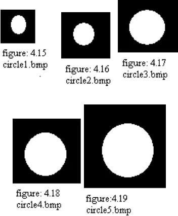
1. Circle images and their chain codes.
2. Squares images and their chain code
Experimental analysis of chain code:
From the above figures it is noticed that in the figure all circle 3 ,4 and 5 circles are varied in size but their chain code is equal. Similarly when we observed the figure all square the chain code of 2 & 3 images are same. Because of these results it did not detect the shape of the image. In the above experimental analysis it is observed that The chain code of one image is repeated with the other image so when unknown image is provided then which image it detect, because the chain code of the image is not unique. Regarding with the shape identification we can use another technique called as Moment invariant, which computes the moment invariants of the image F.
Working of Moment Invariant Technique:
The working of the matlab program for calculating moment invariant.
The steps involved in the program are as follows.
1.First read the circle image i.e.(first image of circle). 2.Then resize the image by 200.then store the image in the
variable i.e.( A2)
3.Image is provided to the function abs (log (Invmoments(A2))).
Here it display the seven moments. Store that moment in variable i.e. (A3).
Through these three steps we have calculate the moments of 50 images.
70 moments of each circles, squares, triangles, rectangles, and ellipses.
Then we have calculated the mean of 70 moments i.e. mean for 70 circle moments to ellipses. Store that mean as a standard mean in the variables.
E.g. mean of circle stored in circle variable
Circle = [1.83317 9.42672 15.99391 18.58508 41.96694 27.53624 44.9427];
Like this all the mean stored in the respective variable.
So, we have 5 standard means.
a. Circle = [1.83317 9.42672 15.99391 18.58508 41.96694 27.53624 44.9427];
b.Square =[1.79064 10.25936 20.5567 20.91698 44.57692 29.80864 46.0892];
c. Triangle = [1.46347 4.13716 5.10721 7.12802 14.4691 11.37922 14.77545];
International Journal of Emerging Technology and Advanced Engineering
Website: www.ijetae.com (ISSN 2250-2459, Volume 2, Issue 9, September 2012)192 e. Ellipse = [1.65277 4.5091 16.58614 18.80252
37.90409 32.07347 40.54282];
4. In this step we provide the unknown image. Repeat the steps 1 to 3.
5. Calculate the difference between unknown image mean and standard image mean using formula AC = sum (abs (A3-circle)). (AC is a circle variable in which the difference between circle image mean and unknown image mean is stored, AS stored square difference, similarly AT, AR, AE.)
6. Repeat the step 5 for square, triangle, rectangle, & ellipse.
7. Compare all the results i.e. compare all the variables AC, AS, AT, AR, AE.
8. After comparing above variables, finally we get the result the i.e. the variable which has value less than or equal to unknown image. The result will display the identified image.(if the AC is less than or equal from the other variables then the identified image is CIRCLE.
Some stored database images are given below
.
Experimental Analysis of Moment Invariant Technique:
[image:7.612.80.256.394.607.2]After executing the function moment invariant on 50 images in the program, table 1 shows the accuracy of the result, which is better than chain code technique.
Table 1 Rate of accuracy
Geomet ric shape
Circ le
Squa re
Trian gle
Rectan gle
Ellip se
%of accura cy
Circle 04 06 - - - 40%
Square 01 03 - 06 - 30%
Triangl e
- - 10 - - 100%
Rectan gle
- - - 10 - 100%
Ellipse - 01 - 02 07 70%
Total - - - 68%
IV. CONCLUSION
International Journal of Emerging Technology and Advanced Engineering
Website: www.ijetae.com (ISSN 2250-2459, Volume 2, Issue 9, September 2012)193
REFERENCES
[1] Cui, F.-y.; Zou, L.-j; Bei Song,IEEE International Conference on,‖ Edge feature extraction based on digital image processing techniques”, Page(s):2320 – 2324, 1-3 Sept. 2008.
[2] Gonzalez, R.C. and R.E. Woods, ―Digital Image Processing‖ Reading, Massachusetts: Addison-Wesley. 716, 1992,
[3] Abby A. Goodrum‖ Image information retrieval An overview of current research.
[4] Giardina, C.R. and E.R. Dougherty, ―Morphological Methods in Image and Signal Processing‖., Englewood Cliffs, New Jersey: Prentice–Hall. 321, 1988.
[5] Gabriel Taubin David B. Cooper† Published in Geometric Invariance in Computer Vision, J.L. Mundy and A.Zisserman, eds., MIT Press, pp. 375-397, 1992
[6] Sohi,D.S.;Devgan,S.S.Proceedings of the IEEE on,‖Application to enhance the teaching and understanding of basic image processing techniques‖, Page(s):413 – 416,. 7-9 April, , Southeastcon 2000.
[7] Lee, J.S.L., R.M. Haralick, and L.S. Shapiro, 8th International Conf. on ―Morphologic Edge Detection. in Pattern Recognition‖, Paris, 1986
[8] Sukhjinder Singh, R. K. Bansal, Savina Bansal ―International Journal of Advanced Research in Computer Science and Software EngineeringVolume 2, Issue 3,‖ March 2012 Paschalakis, S.; Lee, P , Seventh International Conference on,’’Pattern recognition in grey level images using moment based invariant features’’, Volume 1, Page(s):245 – 249, 13-15 July 1999.
[9] Lee, Shih-Jong J., ―method for identifying objects using data processing techniques‖, us patent 5,710,842, 382/283, jan2003.
[10]Kampel, M.; Huber-Mork, R.; Zaharieva, M , ―Image-Based Retrieval and Identification of Ancient Coins “,Volume 24, Page(s):26 – 34, March-April 2009.
[11]M. K. Hu, ―Visual pattern recognition by moment invariants,‖ IRE Trans.Information Theory, vol. 8, pp. 179–187, 1962.
[12]International Conference on, ― Identifying objects using cluster and concept analysis‖, Proceedings of the 1999.
[13]Henry Hamdan, ―shape recognition using image processing‖ school of computer and commu. engineering university Malaysia Parlis, 2007.
[14]Yuan-Kai Wang; Kuo-Chin Fan, Proceedings of the 13th International Conference on ―Applying genetic algorithms on pattern recognition: an analysis and survey”, Volume 2, Page(s):740 – 744, 25-29 Aug. 1996.
[15]Predrag Pejnovic,Milan Markovic, Srdjan Stankovic,‖classification of Two-Dimensional Shapes Based on Moment Invariant‖ University of Belgrade, Faculty of Electrical Engineering, Bulevar Revolucije 73
[16]Machon B. Gregory, Ben Shneiderman, ”Shape Identification in Temporal Data Sets‖ Dept. of Computer Science University of Maryland.
[17]Vajda F., IEE Colloquium on “Techniques and trends in digital image processing and computer vision”, Page(s):1/1, 1994.
[18]Freeman, H., Boundary encoding and processing, in Picture Processing and Psychopictorics, B.S. Lipkin and A. Rosenfeld, Editors. 1970, Academic Press: New York. p. 241-266.
[19]Lu; Hong-guo Xu; Yi-bing Li; IEEE International Conference on,’’Line detection based on chain code detection’ Page(s):98 - 10314-16 Oct. 2005
[20]Lele Zhou; Zahir, S.; IEEE International Symposium on,’’A New Efficient Context-Based Relative-directional Chain Coding’’ Page(s):787 – 790, Aug. 2006.
[21]Neeta Nain, Vijay Laxmi, Bhavitavya Bhadviya and Nemi Chand Singh ―Corner Detection using Difference Chain Code as Curvature‖ Proceedings of the International MultiConference of Engineers and Computer Scientists 2008 Vol I IMECS 2008, 19-21 March, 2008, Hong Kong
[22]Dr. Azzam Talal Sleit & Rahmeh Omar Jabay (Previously, Azzam Ibrahim) ―A Chain Code Approach for Recognizing Basic Shapes‖ King Abdullah II for Information Technology College University Of Jordan, Amman, Jordan.