ii
MOHAMED ASGHAIYER MOHAMED
Aproject report is Submitted In partial Fulfillment of the Requirements for The Award of The Degree of Master of Electrical Engineering
Faculty of Electrical and Electronic Engineering University Tun Hussein Onn Malaysia
JUNE, 2015
DESIGN OF SHUNT ACTIVE POWER FILTER TO MITIGATE
vi
ABSTRACT
vii
ABSTRACT
viii
TABLE OF CONTENTS
TITLE ii
DECLARATION iii
DEDICATION iv
ACKNOWLEDGEMENT v
ABSTRACT vi
ABSTRACT vii
CONTENTS viii
LIST OF TABLE xi
LIST OF FIGURES xii
LIST OF SYMBOLS AND ABBREVIATIONS xv
CHAPTER 1: INTRODUCTION
1.1 Introduction 1
1.2 Problem statement 2
1.3 Objective 3
1.4 Scope of project 3
CHAPTER 2: LITERATURE REVIEW
2.1 Introduction 4
2.2 power quality problems 5
2.3 Harmonic 5
2.3.1 Total harmonic distortion 7
2.3.2 IEEE standard for harmonic 7
2.4 power factor 8
2.4.1 Power factor with linear loads 9
2.4.2 Power factor with nonlinear loads 10
2.5 Effect Harmonic 13
2.5.1 Effect on Transformer 14
2.5.2 Effect on Capacitor bank 14
2.5.3 Neutral conductor over loading 15
2.5.4 Effect on lines and cables 15
ix
2.5.6 Undesired operation of fuse 16
2.6 Type of power filter 16
2.6.1 Passive power filter 16
2.6.2 Active power filter 17
2.6.2.1 Configuration of active power filter 19 2.6.2.1.1 Series active power filter 19 2.6.2.1.2 Shunt active power filter 20 2.6.2.1.3 Hybrid active power filter 20 2.6.2.2 Type of active power filter 21
2.7 Previse reaches 24
CHAPTER 3: METHODOLOGY
3.1 Introduction 31
3.2 Flow chart of project 32
3.3 Block diagram of methodology 33
3.4 Principle of Shunt active power filter 34 3.5 Design Shunt APF based on instantaneous P-Q Theory 34 3.6 Architecture of simulation of shunt active power filter 38
3.6.1 Voltage source inverter 38
3.6.2 P-Q & I-Compensation calculation 39
3.6.2.1 Clarke V 40
3.6.2.2 Clarke I 40
3.6.2.3 P Q Calculation 41
3.6.2.4 Low pass filter 41
3.6.2.5 Alpha Beta current 42
3.6.2.6 Compensation current 42
3.6.3 The hysteresis band current controller 43 3.6.4 DC Bus Voltage control by using PI controller 43
CHAPTER 4: RESULTS AND ANALYSIS
4.1 Introduction 44
4.2 Parameters of simulation 44
4.3 Test simulation and results 45
4.3.1 Simulation with linear load 45
4.3.2 Simulation with nonlinear loads 44
4.3.2.1 RL load(1) 49
4.3.2.2 RL load (2) 52
4.3.2.3 Additional load with LR 54
x
CHAPTER 5: CONCLUSION & FUTURE WORK
5.1 Introduction 60
5.2 Conclusions 60
5.3 Recommendation 61
xi
LIST OF TABLES
2.1 Current distortion limits (in % of ) for general distribution system (120-69kV)
08
2.2 Comparison of passive power filter and active power filter 18
2.3 Comparison of low pass and high pass and band pass active filter 22
2.4 Compare between the topology of APF 23
2.4 Previous Researches 24
4.1 The simulation parameters values used in this project 46
4.2 The results of simulations 58
xii
LIST OF FIGURES
2.1 Periodic distorted waveform 6
2.2 Resultant waveform of system having 3rdto 15th harmonics 6
2.3 Power triangle 12
2.4 Behavior displacement power factor and total harmonic distortion 12
2.5 Magnification of harmonic number 13
2.6 Active power filter connect with network 18
2.7 Series active power filter connected to network 19
2.8 Shunt active power filter connected to network 20
2.9 Series of shunt active power filter and passive power filter 21
2.10 Parallel active power filter and passive power filter 21
2.11 Low pass APF 22
2.12 High pass APF 22
2.13 Band pass APF 22
3.1 Flowchart of project 32
3.2 Block diagram of methodology 33
3.3 Shunt active power filter topology 34
3.4 Concept of different powers between power source and load 37
3.5 Shunt active power filter in 3-phase system 37
3.6 Connection in the inverter 39
3.7 The blocks required for calculation of compensation current 39
3.8 Clark voltage and its function 40
xiii
3.10 Calculation of PQ 41
3.11 Low pass filter 41
3.12 Alpha Beta current 42
3.13 The block of Compensation current 42
3.14 The hysteresis band current controller 43
3.15 Connect PI controller 44
4.1 Simulation with linear load 47
4.2 Source current waveform with linear load 47
4.3 Source voltage waveform with linear load 47
4.4 THD of linear load and waveform by FFT 48
4.5 Simulation with nonlinear load 48
4.6 Simulation with shunt active power filter 49
4.7 Source and load voltage waveform with and without shunt APF 49
4.8 Source and load current waveform without shunt APF 50
4.9 THD without shunt APF 50
4.10 Current waveform after and before shunt APF 51
4.11 Current signal and THD after shunt APF by FFT 51
4.12 Source and load voltage waveform with and without shunt APF 52
4.13 Source and load current waveform with and without shunt APF 52
4.14 The analysis THD without shunt APF 53
4.15 The analysis of THD with shunt APF 53
4.16 The analysis of signal with shunt APF 54
4.17 The analysis of THD without shunt APF 54
4.18 The analysis of signal with shunt APF 55
4.19 The analysis of signal with shunt APF 55
4.20 The analysis of THD without shunt APF 56
xiv
4.22 The waveforms of current with unbalanced load 56
4.23 The waveform of current generated by shunt APF 57
4.24 The waveform of current after shunt APF 57
xv
LIST OF SYMBOLS AND ABBREVIATIONS
PQ Power quality
PS Power system
PPF Passive power filter
HV High voltage
AC Alternating current DC Direct current APF Active power filter
PF power factor
THD Total harmonic distortion HAPF Hybrid active power filter PFC Power factor correction
IEEE Institute of electrical and electronic engineers
H Harmonic
Total current
F Frequency
HZ Hertz
maximum short –circuit at PCC
maximum demand load current at PCC
Real power
Reactive power
S Apparent power
Qc Capacitor power bank Displacement power factor
Distortion power factor
Total power factor
Ls Source inductor
C Capacitor
R Resistor
capacitive reactive power
Load current
Source current
Filter current
VSI Voltage source inverter CSI Current source inverter Se APF Series active power filter Sh APF Shunt active power filter LPF Low pass filter
xvi
BPF Band pass filter cut off frequency PCM Power control mode PI Proportional- integral PWM Pulse width modulation
1
CHAPTER 1
INTRODUCTION
1.1 Introduction
Power Quality (PQ) issues are becoming a major concern of today’s power system (PS) engineers. Harmonics play significant role in deteriorating PQ, called harmonic distortion. Harmonic distortion in electric distribution system is increasingly growing due to the widespread use of nonlinear loads. Large considerations of these loads have the potential to raise harmonic voltage and currents in an electrical distribution system to unacceptable high levels that can adversely affect the system currents. IEEE standards have defined limits for harmonic voltages and harmonic [1].It has been lost in distribution system , current harmonics cause serious harmonic problems in distribution feeders for sensitive consumers .some technology solutions have been reported in order to solve PQ [1.2] .
2
changing system conditions. Thus, the active power filter (APF) was introduced to compensate harmonics and reactive power[ 3].
There are three types of APF which are shunt APF, series APF and hybrid APF which is the combination of AP with PPF.
The purpose of APF power line conditioner is to compensate the utility line current waveform so that it approximates a sine wave in phase with the line voltage when a nonlinear load is connected to the system. Classically, shunt power line conditioner (shunt PPF) consists of tuned LC filters and/or high pass filters are used to suppress harmonics and power capacitors are employed to improve the power factor (PF) of the utility/mains. But these conventional methods have the limitations of fixed compensation, large size and can also excite resonance conditions [1, 4]. Hence APF is introduced as a viable alternative to compensate harmonics and improve PF.
This project is focusing on the application of APF in treating the harmonics distortion in distribution system by determining low Total Harmonics Distortion (THD) value and improving the system’s power factor (PF).
1.2 Problem Statement
Harmonics play significant role in deteriorating PQ, called harmonic distortion. Harmonic distortion in electric distribution system is increasingly growing due to the widespread use of nonlinear loads.
3 1.3 Objectives of research
The objectives of this project can be summarized as follows:
To design an shunt APF
To investigate the (Shunt APF) under different nonlinear load conditions.
To analyse the harmonic spectrum of the system and achieve low THD
1.4 Scope of project
Represent the linear load R Represent the nonlinear load with RL load, and analysis as the distorted source current waveform drawn by the nonlinear load.
4
CHAPTER 2
LITERATURE REVIEW
2.1 Introduction
This chapter will discuss about the literature review of the project. The sources of the information had been gathered from books, journals, research papers, newspapers, magazines, hand books and thesis.
5 2.2 Power quality problems
Institute of Electrical and Electronic Engineers (IEEE) Standard IEEE1100 defines PQ as “the concept of powering and grounding sensitive electronic equipment in a manner suitable for the equipment.” As appropriate as this description might seem, the limitation of PQ to “sensitive electronic equipment” might be subject to disagreement. Electrical equipment susceptible to power quality or more appropriately to lack of PQ would fall within a seemingly boundless domain [5].
All electrical devices are prone to failure or malfunction when exposed to one or more PQ problems [4.]. The electrical device might be an electric motor, a transformer, a generator, a computer, a printer, communication equipment, or a household appliance. All of these devices react adversely to PQ issues, depending on the severity of problems [5.6]. PQ can be roughly broken into categories as follows:
1. Steady-state voltage magnitude and frequency 2. Voltage sags
3. Grounding 4. Harmonics
5. Voltage fluctuations and flicker 6. Transients, and
7. Monitoring and measurement
2.3 Harmonic (H)
6
In the recent time we have been notifying a big change in the use of non‐linear loads. Due to this the value of harmonic non‐sinusoidal currents and voltages has also increased up to a great extent in the system. These harmonic elements affect the overall PS as well as the client’s equipment’s also .So today the issue of maintaining the PQ is a big issue.
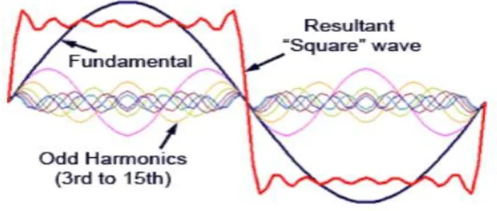
Harmonics are defined sinusoidal voltages or currents having frequencies that are whole multiples of the frequency at which the supply system is designed to operate (50 Hz or 60 Hz). Figures (2.1) and (2.2) show that any periodic distorted waveform can be expressed as a sum of pure sinusoids. The harmonic number (h) usually specifies a harmonic component, which is the ratio of its frequency to the fundamental frequency [9.10].
Figure (2.1) shows periodic distorted waveform .
[image:18.595.152.512.347.482.2] [image:18.595.156.507.565.714.2]7
Harmonics have frequencies that are integer multiples of the waveform fundamental frequency. For example, given a 60 Hz fundamental waveform, the , harmonic components will be at 120 Hz, 180 Hz, 240
Hz and 300 Hz respectively Thus, harmonic distortion is the degree to which a waveform deviates from its pure sinusoidal values as a result of the summation of all these harmonic elements. The ideal sine wave has zero harmonic components. In that case, there is nothing to distort this perfect wave[11.12].
2.3.1 Total harmonic distortion (THD)
THD of a signal is a measurement of the harmonic distortion present in current or voltage. It is defined as the ratio of the sum of the powers of all harmonic components to the power of the fundamental frequency [7-9].
(n = 2,3,4,5…..∞) (2.1)
Where
is the fundamental component of the current is the total current
Harmonic distortion can have detrimental effects on electrical distribution systems, It canwaste energy and lower the capacity of an electrical system; it can harm both the electrical distribution system and devices operating on the system. Understanding the problems associated with harmonic distortion, it causes and effects, as well as the rnethods of dealing with it, is of great importance in minimizing those effects and increasing the overall efficiency of the distribution system [13. 14]
2.3.2 IEEE standard for harmonic
8
as variable frequency (F) drives, it became necessary to revise the standard [12.15].
The IEEE working groups of the power engineering society and the industrial applications society prepared recommended guidelines for PQ that the utility must supply and the industrial user can inject back onto the power distribution system. The revised standard was issued on April 12, 1993 and titled“IEEE recommended practices and requirements for harmonic control in electrical power systems [15 ] .
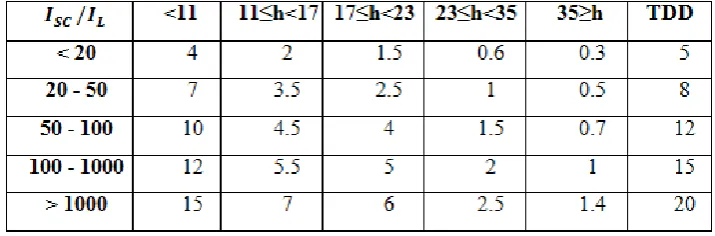
The IEEE 519 standard clearly states that harmonic current should be reduced to voltage distortion, table (2.1) show that limits of current.
Table (2.1) current distortion limits for distribution system (120 through 69,000 v)
Where;
= maximum short –circuit at PCC = maximum demand load current at PCC
2.4 Power Factor (PF)
In PS, wasted energy capacity, also known as poor PF, is often overlooked. It can result in poor reliability, safety problems and higher energy costs. The lower PF, the less economically your system operates.
[image:20.595.157.515.365.483.2]9
(2.2)
(2.3)
Where;
is active power is apperant power
PF is commonly referred to in percent, with 100% being a perfect PF, also called unity. At unity PF, the kVA
= kW, therefor the utility company does not supply any reactive power [12].
2.4.1 Power factor with linear loads
When the loads connected to the system are linear and the voltage is sinusoidal, the PF is calculated with the following equation:
PF= cos (ϕ )
(2.4)Unfortunately, this formula has led to a misunderstanding of the PF concept. PF is the proportional relation of the active power (or working power) to the S (total power delivered by the utility or consumed by the load) [16]. Using this definition, the PF must be calculated as:
Where;
P = VI cos(ϕ )
(2.5)
S = VI
(2.6)
10
adding a capacitor bank connected in parallel with the PS , to calculate the capacitor banks to be installed, use the following method:
Select the month in which the bill is highest (kVArh to be billed)
Assess the number of hours the installation operates each month
Calculate the capacitor power Qc to be installed
(2.7)
The capacitor bank supplies most of the reactive power needed by the load and a small amount is supplied by the utility (Q2).The original angle ( ϕ1(between the P and S is reduced to a smaller value )ϕ2( and the PF is improved because
cos )ϕ 2( > cos) ϕ1( .
It is very important to note that the reduction in the angle obtained by the PF improvement is a result of the vector relationship between the active, reactive and S, but what we are really doing is reducing the Q, consequently the S is also reduced and the PF is increased [17,18]
2.4.2 Power factor with non–linear loads
A non-linear load on a PS is typically a rectifier or device such as (a fluorescent lamp, electric welding machine, or arc furnace). Because current in these systems is interrupted by a switching action, the current contains frequency components that are multiples of the PSF. Distortion PF is a measure of how much the harmonic distortion of a load current decreases the average power transferred to the load[19].
11
The active power is the mean (or average) value of the instantaneous power, so it can be calculated
(2.8)
The rms value of current is a function of the and the rms value of the fundamental component of current can be calculated by:
(2.9)
The PF for non–linear loads, can be calculated using equations (2.6), (2.8) and (2.9).
Pf =cos (
)
(2.10)
Where:
cos ( ) is called displacement power factor
because it depends on the phase angle between the voltage and the fundamental component of the current, and it is similar to the PF calculated with linear loads and sinusoidal voltage .
is called distortion power factor because it depends on the current harmonic distortion .
Thus, The total power factor ) calculated as the product of the and
the is known as
(2.11)
If the Q of the loads increases, the displacement angle between the voltage and the fundamental component of the current also increases and the total PF
decreases. Likewise, if the THD of current increases, the decreases. It is clear by equation (2.9) that will always be lower than the whenever harmonic distortion is present. can only be achieved when both
and are corrected. This requires a two steps process:
Reduce the displacement angle between voltage and current
12
If either of these steps is taken without the other the will be increased but it may not be high enough to reach the minimum value required by the utility. Additionally, if one step is taken without the other, the and the corresponding efficiencies will not be achieved.
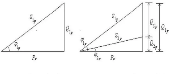
Now, vector relationship, as shown in figure( 2. 3A), can be obtained from the P, the fundamental ( ) and the fundamental ( ) prior to
displacement power factor improvement. This relationship allows us to visualize the effect that a capacitor bank (QCF ) has on correcting the displacement power factor figure(2.3.B).
Whenever capacitors are used, care should be taken to avoid a resonant condition between the capacitor bank and the main transformer.
Figure (2.3.A) figure (2.3.B)
The can be improved by decreasing the harmonic current distortion, which is accomplished by using a filter instead of a capacitor bank. The capacitive part of the filter improves the , while the combination of the reactor and the capacitor bank decrease the THD of the current. A twofold result is achieved, that is improvement of the and improvement of the . If a capacitor bank were used instead of a filter, the would
have been improved. If there is no resonance, the distortion power factor does not change and the increases only because the also increases, but the may not be high enough to reach the minimum value required by the utility. Of a resonant condition is created between the capacitor bank and the main transformer, the THD of current increases so the degrades and the
[image:24.595.142.478.341.488.2]13
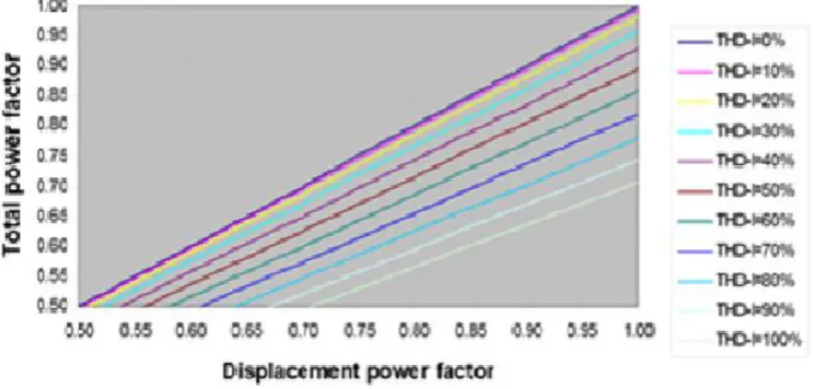
The figure (2.4) shows the behaviour of the for different values of
and THD of current.
Figure (2.4) show the behaviour and THD
2.5 Effect of Harmonics
Harmonics are a major cause of power supply pollution lowering the power factor and increasing electrical losses. The effect of harmonic results in premature equipment failure and also cause of requirement of equipment of high rating The voltage distortion produced in the system is the major issue with the harmonics distribution. The electronics equipment used in the system usually generate harmonics more than one. In all type of harmonics the tripled harmonics are more severe example of triplet harmonics are 3rd 9th 15th [20.21].
[image:25.595.147.520.147.325.2]14
frequency neutral current magnitude reaches up to 1.75 times of average phase current [20]. Under above discussed case if the load of system increase may become cause of failure of insulation of neutral conductor which further result in the breakdown of transformers winding. The important and major effect of Harmonics is further discussed as:
2.5.1 Effect on Transformer
Harmonics effect transformer losses and eddy current loss density [23]. Actually, the harmonic effects on transformer will not be notice until actual failure occurs. It will occurs when there has been changes that been made to the system like additional or replacement of new loads. Overheating of transformer is always been related with harmonics effects.
Harmonics produce addition losses in the transformer core as the higher frequency harmonic voltages set up hysteresis loops, which superimpose on the fundamental loop. Each loop represents higher magnetization power requirement and higher core losses.
Because of harmonics, the losses in conductor will increase. The resultant current will increase the distortion and is given by equation (2.1).Overheating also can occur when there is resistive skin effect and winding proximity effect [13]
2 .5.2 Effect on Capacitor bank
15 2.5.3 Neutral conductor over loading
In single phase PS neutral play a very important role as they carry the return current and complete the circuit. But in case of harmonics it also becomes the return path for the harmonic current to transformer through neutral connection. For an unbalanced system the unbalanced currents are passed through the neutral and for this purpose we need to balance the system the size of neutral cable is almost taken equal to its phase cable. Under environment of harmonics the unbalanced current which is passed through the neutral produces a heat loss in the system which again affects the power quality of distribution system [25]
2.5.4 Effect on lines and cables
Harmonic distortion in a distribution system affects the system current and significantly. These increased rms currents produce additional heat losses in the system lines and cables Harmonic distortion in cables affect by increasing the dielectric stress in the cables. This stress is proportional to the voltage crest factor which represents the crest value of voltage waveform to rms value of waveform. The effect of this increased stress is such that, the cable useful life is shortened, causing faults, which ultimately increases the system capital and maintenance cost [26].
2.5.5Thermal effect on rotating machine
16 2.5.6 Undesired operation of fuse
In the environment of harmonic the RMS value of voltage and current may increase. This tendency will lead the problem of unexpected operation of fuse in capacitor banks or other arrangements which are used in the system to make operation of nonlinear load. If the fuse of one connected phase blown off then the other remaining fuse is in operation under a stress. In this condition the system become unbalanced and it will tends to produce the overvoltage in the system. To summarize above discussion it is concluded that, the following problems arise due to harmonics [29].
Equipment overheating
Equipment malfunction or operation failure of equipment
Equipment failure
Communications interference
Fuse and breaker operation failure
Maintenance problem
To overcome such issues, there are various harmonic mitigation methods that we can use to address harmonics in the distribution system. They are valid solutions depending on circumstances, and have their pros and cons. One of the way out to resolve them using filters [30] . The filters are widely used for reduction of PQ problems with the increase of nonlinear loads in the PS more and more filters are required
.
2.6 Types of power filter
Filter is method to reduce harmonics in an industrial plant when the harmonic distortion has been gradually increased or as a total solution in a new plant. Broadly there are two basic methods: PPF and APF.
2.6.1 Passive power filter ( PPF )
17
capacitor (C) provides low impedance path for a single (tuned) frequency. An inductor (Ls) is required to detune the filter from the electrical system and other filters’ resonance point. This type of filter is very application specific. It can only mitigate a single frequency, and it injects leading reactive current (kVAr) at all times. But it is economical if you only need to deal with a dominant harmonic in the facility. It normally can reach THD target of 20% [31].
2.6.2 Active power filter (APF)
18
Figure (2.6) shows the connection of APF
The APF present many other advantages over the traditional methods for harmonic compensation such as [34]:
Adaptation with the variation of the loads
Possibility of selective harmonics compensation.
Limitations in the compensation power.
Possibility of reactive power compensation.
[image:30.595.174.483.74.220.2] [image:30.595.144.523.462.715.2]19 2.6.2.1 Configuration of (APF )
APF’s can be classified based on converter type, topology, and the number of phases [34. 35]. The converter type is mainly two types:
voltage source inverter (VSI)
Current source inverter (CSI).
The topology of APF is classified in to three types.
Series active power filters (Se APF).
Shunt active power filters (Sh APF).
Hybrid active power filters (HAPF) .
Finally based on the phases the APF mainly two types:
Two-wire (single phase) system.
Three or four wire three phase system.
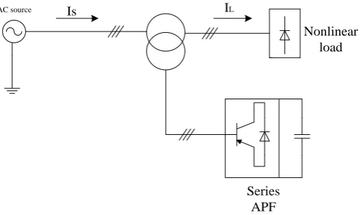
2.6.2.1.1 Series Active Power Filter (series APF)
The aim of the series APF is to locally modify the impedance of the grid. It is considered as harmonic voltage source which cancel the voltage perturbations which come from the grid or these created by the circulation of the harmonic currents into the grid impedance. However, series APFs cannot compensate the harmonic currents produced by the loads [36.37 ] figure (2.7) shows Series APF connected to the network.
AC source Is IL
Nonlinear load
Series APF
[image:31.595.202.466.556.713.2]20
2.6.2.1.2 Shunt Active Power Filter (shunt APF)
The shunt APFs are connected in parallel with the harmonic producing loads. They are expected to inject in real time the harmonic currents absorbed by the pollutant loads. Thus, the grid current will become sinusoidal [36,38. 39].
AC source
Is IL
Nonlinear load
Shunt APF
PCC
. Figure (2.8) Shunt APF connected to the network
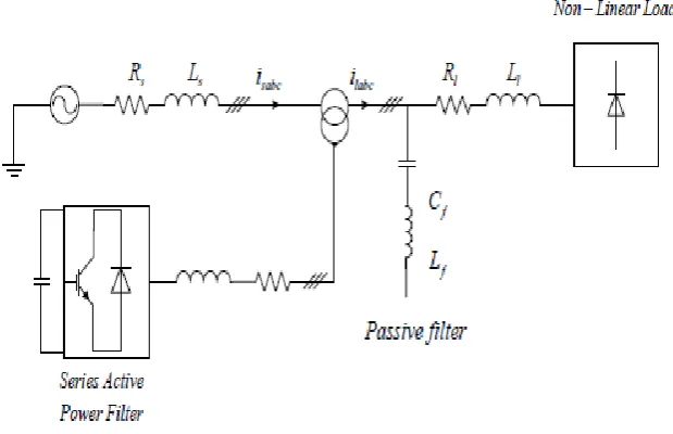
2.6.2.1.3 Hybrid Active Power Filter (HAPF)
[image:32.595.194.467.215.385.2]21
AC source Is IL
Nonlinear load
Shunt APF
PCC
Passive filter
Figure (2.9) Parallel of SAPF and PPF
Figure (2.10) Series APF with PPF
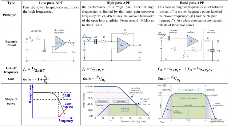
2.6.2. Types of Active power Filter
There are three most common types of APF based on cut-off frequency show the compare between them in table (2.3)
Low pass filter (LPF)
High pass filter (HPF)
[image:33.595.195.471.83.265.2] [image:33.595.176.486.319.519.2]22
Table (2.3) shows Comparison of LPS ,HPF and BPF active power filter
Type Low pass APF High pass APF Band pass APF
Principle
Pass the lower frequencies and reject the high frequencies
the performance of a “high pass filter” at high frequencies is limited by this unity gain crossover frequency which determines the overall bandwidth of the open-loop amplifier.From around 100kHz up to about 1GHz.
This band or range of frequencies is set between two cut-off or corner frequency points labelled the “lower frequency” (ƒL) and the “higher
frequency’’( ƒH ) while attenuating any signals
outside of these two points .
Example Circuit
Cut-off
frequency
/
Gain
[image:34.842.49.800.96.506.2]23
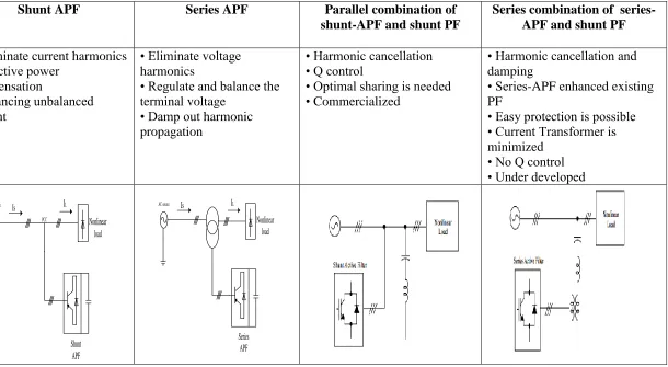
Table (2.4) shows compare between the topology of APF
Type of filter
Shunt APF Series APF Parallel combination of
shunt-APF and shunt PF
Series combination of series-APF and shunt PF
Advantage/ disadvantage
• Eliminate current harmonics • Reactive power
compensation
• Balancing unbalanced current
• Eliminate voltage harmonics
• Regulate and balance the terminal voltage
• Damp out harmonic propagation
• Harmonic cancellation • Q control
• Optimal sharing is needed • Commercialized
• Harmonic cancellation and damping
• Series-APF enhanced existing PF
• Easy protection is possible • Current Transformer is minimized
• No Q control • Under developed
Circuit
AC source Is IL
Nonlinear load
Shunt APF
PCC
AC source Is IL
Nonlinear load
[image:35.842.170.780.108.443.2]24
2.7 Previous Research
The table (2.1) below shows the summary from the previous research
.
N0 year Author Title Duplication outcomes Methodology Remarks
journal V O L
No PP Tools Technique
1 2014 Priya- et
al
Simulation results
of a shunt APF
using p-q theory
power
components
calculation
IJARC SMS
2 2321-7782
247-254
Shunt APF is reduced THD in surce current at level well below the defined standards (from 30.28% to 0.11% ) ,and also mitigate the effect of PFC
Matlab p-q theory with HCC , PI controlle rs
To consider the effect of zero sequence in the supply voltage
2 2013 Bhakti et-al
Reduction in harmonic distortion of the system using active power filter in Matlab
IJACS MS
3 6
60-64
Explanation about APF to minimizes THD within an acceptable range (from 30.42% to 3.62)
Matlab modify APF
Need to discuss about reactive power.
To provide more cases for PQ
REFERENCE
[1] Bhonsle, D. C., & Kelkar, R. B. (2011, December). Design and simulation of single phase shunt active power filter using MATLAB. In Recent Advancements in Electrical, Electronics and Control Engineering (ICONRAEECE), 2011 International Conference on (pp. 237-241). IEEE.
[2] Sultan, S. S., & Darwish, M. K. (2012, March). Power quality evaluation in libyan electrical distribution networks. In Renewable Energies and Vehicular Technology (REVET), 2012 First International Conference on (pp. 372-378). IEEE.
[3] Rahmani, S., Mendalek, N., & Al-Haddad, K. (2010). Experimental design of a nonlinear control technique for three-phase shunt active power filter. Industrial Electronics, IEEE Transactions on, 57(10), 3364-3375.
[4] Jain, S. K., & Agarwal, P. (2003). Design simulation and experimental investigations, on a shunt active power filter for harmonics, and reactive power compensation. Electric Power Components and Systems, 31(7), 671-692.
[5] Kaur, S. (2014). submitted in partial fulfillment of the requirements for the award of degree of (Doctoral dissertation, THAPAR UNIVERSITY, PATIALA).
[6] Ramya, P., & Arpitha, C. N. (2013). Reduction of THD in power system using generalized UPQC.
[8] Henzler-Wildman, K., & Kern, D. (2007). Dynamic personalities of proteins. Nature, 450(7172), 964-972.
[9] Wakileh, G. J. (2001). Power systems harmonics: fundamentals, analysis and filter design. Springer Science & Business Media.
[10] Bollen, M. H. J. (2003). What is power quality?. Electric Power Systems Research, 66(1), 5-14.
[11] Gerçek, C. Ö. (2007). optimizing transient and filtering performance of A C-type 2 .Harmonic power filter by the use of solid-state switches (Doctoral Dissertation, Middle East Technical University).
[12] Arpaia, P. (2014). Power measurement. Measurement, Instrumentation, and Sensors Handbook: Electromagnetic, optical, radiation, chemical, and biomedical measurement, 2, 1.
[13] Seymour, J., & Horsley, T. (2005). The seven types of power problems. White paper, 18.
[14] Modak, S., Das, T. K., & Nabi, M. R. (2014). Improvement of power quality of CFL bulbs using active power factor correction circuit (Doctoral dissertation, BRAC University).
[15] RASHID, I. M. (2013). Analysis of the harmonic problems in three phase transformers and solution using passive filters (Doctoral dissertation, NEAR EAST UNIVERSITY).
[16] Schamp, B., & Scrimshaw, N. S. close this book Chronic Energy Deficiency: Consequences and Related Issues (IDECG, 1987, 201 p.).
[18] Burke, J. J. (1994). Power distribution engineering: fundamentals and applications. CRC Press.
[19] Mohanty, P., & Sahoo, S. (2010). Analysis of two level and three level inverters (Doctoral dissertation).
[20] Osborne, M. M., Kitchin, R. H., & Ryan, H. M. (1995). Custom power technology in distribution systems: an overview.
[21] Frye, J. (2006). Performance-objective design of a wind-diesel hybrid energy system for Scott Base, Antarctica.
[22] Özgen, C. (2007). Prediction of hot-spot and top-oil temperatures of power transformers according to IEEE Standards C57. 110-1998 And C57. 91-1995 (Doctoral Dissertation, Middle East Technical University).
[23] Shertukde, H. M. (2014). Distributed Photovoltaic Grid Transformers. CRC Press.
[24] Plummer, I. (2011). Asymmetry in Distribution Systems: Causes, Harmful Effects and Remedies (Doctoral dissertation, Louisiana State University).
[25] Ghosh, A., & Ledwich, G. (2012). Power quality enhancement using custom power devices. Springer Science & Business Media.
[26] Shukla, A. K. (2009). Studies on Power Quality and An LSE & PSOPC Based Harmonic Estimation to Real Time Data (Doctoral dissertation, National Institute of Technology Rourkela).
[28] F II, I. (1993). IEEE recommended practices and requirements for harmonic control in electrical power systems.
[29] Adams, J., Pappu, V. A., & Dixit, A. (2012, July). ERCOT experience screening for Sub-Synchronous Control Interaction in the vicinity of series capacitor banks. In Power and Energy Society General Meeting, 2012 IEEE (pp. 1-5). IEEE.
[30] Das, J. C. (2011). Power system analysis: short-circuit load flow and harmonics. CRC press.
[31] Han, C. (2006). Power system dynamic voltage management with advanced STATCOM and energy storage system. ProQuest.
[32] Rudnick, H., Dixon, J., & Moran, L. (2003). Delivering clean and pure power. Power and Energy Magazine, IEEE, 1(5), 32-40.
[33] Salam, Z., Tan, P. C., & Jusoh, A. (2006). Harmonics mitigation using active power filter: A technological review. Elektrika, 8(2), 17-26.
[34] Gyugyi, L. (1994). Dynamic compensation of AC transmission lines by solid-state synchronous voltage sources. Power Delivery, IEEE Transactions on, 9(2), 904-911.
[35] Singh, B., Al-Haddad, K., & Chandra, A. (1999). A review of active filters for power quality improvement. Industrial Electronics, IEEE Transactions on, 46(5), 960-971.
[36] Kmail, M. (2012). Investigation Of Shunt Active Power Filter For Power Quality Improvement (Doctoral Dissertation, Near East University).
[38] Bayod-Rújula, A. A. (2009). Future development of the electricity systems with distributed generation. Energy, 34(3), 377-383.
[39] Passey, R., Spooner, T., MacGill, I., Watt, M., & Syngellakis, K. (2011). The potential impacts of grid-connected distributed generation and how to address them: A review of technical and non-technical factors. Energy Policy, 39(10), 6280-6290.
[40] Jiang, Y. H., & Chen, Y. W. (2009, November). Neural network control techniques of hybrid active power filter. In Artificial Intelligence and Computational Intelligence, 2009. AICI'09. International Conference on (Vol. 4, pp. 26-30). IEEE.
[41] Kraimia, H. (2013). Ultra-Low Power RFIC Solutions for Wireless Sensor Networks (Doctoral dissertation, Université Sciences et Technologies-Bordeaux I).
[42] Priya, M. S., & Balu, U. S. (2014). Simulation results of a shunt active power filter using pq Theory Power Components Calculations. International Journal, 2(2).
[43] Kumar, V. S., Kavitha, D., Kalaiselvi, K., & Kannan, P. S. (2008). Harmonic mitigation and power factor improvement using fuzzy logic and neural network controlled active power filter. Journal of Electrical Engineering & Technology, 3(4), 520-527.
[44] Adam, G., Zbant, A., & Livint, G. (2013, May). New Simulink control block for single phase shunt active power filters. In Advanced Topics in Electrical Engineering (ATEE), 2013 8th International Symposium on (pp. 1-4). IEEE.
mitigation of harmonics at the interface of distribution and transmission systems. Industry Applications, IEEE Transactions on, 48(4), 1374-1386.
[46] Rachmildha, T. D. (2011). Optimized Combined System of Shunt Active Power Filters and Capacitor Banks. International Journal on Electrical Engineering and Informatics, 3(3), 326.
[47] Abdalla, I. I., Rao, K. R., & Perumal, N. (2011, March). Three-phase four-leg shunt active power filter to compensate harmonics and reactive power. In Computers & Informatics (ISCI), 2011 IEEE Symposium on (pp. 495-500). IEEE.
[48] Hongda, L., & Cao, K. (2011, August). Active power filter simulation based on instantaneous reactive power theory and the PWM hysteresis control mode. In Electronic Measurement & Instruments (ICEMI), 2011 10th International Conference on (Vol. 4, pp. 95-100). IEEE.
[49] Karvekar, Sushil, Swapnil Gadgune, and Dadgonda Patil. "Implementation of shunt active power filter using sliding mode controller." Circuit, Power and Computing Technologies (ICCPCT), 2014 International Conference on. IEEE, 2014.