International Journal of Emerging Technology and Advanced Engineering
Website: www.ijetae.com (ISSN 2250-2459,ISO 9001:2008 Certified Journal, Volume 3, Issue 3, March 2013)
287
Grid Connected Multi-Input Wind Energy/Dual Battery Power
System with Active Power Filter Capability
C. Sasikumar
1, T. Nandagopal
2,
1PG Scholar, 2Assistant Professor, Department of Electrical and Electronics Engineering, Paavai Engineering college,
Namakkal
Abstract— The main core of this paper is design to generate a constant AC-output voltage irrespective of the wind speed. It is integrated with buck/buck-boost multi input DC-DC converter and a full-bridge DC-AC inverter which supplies grid/residential load in a unified structure. In this structure, each switching cycle of the proposed boost converter is divided into five switching periods. These switching periods introduce five different duty ratios for the proposed boost converter and can be controlled independently. The BESS is used as an energy storage element for the purpose of voltage regulation and acts a dual power source. When power fluctuation occurs in the system, the BESS can be used to level the power fluctuation by charging and discharging operation. The HDGS operates in various operation modes such as normal operation, dispatching operation and power smoothing. The power operation mode in the proposed structure is defined and controlled using fuzzy logic control scheme. At varied level of wind speed power operation modes are verified. It has been simulated using MATLAB/SIMULINK software.
Keywords-Grid Wind energy system, Dual battery, Hybrid power integration, Power quality, Active filter, Fuzzy logic controller.
I. INTRODUCTION
The Conventional energy sources based on oil, coal, and natural gas have proven to be highly effective drivers of economic progress, but at the same time harmful to the environment and to human health. Furthermore, they tend to be cyclic in nature, due to the effects of oligopoly in production and distribution. These traditional fossil fuel-based energy sources are facing increasing pressure on a host of environmental fronts. [1]
The potential of renewable energy sources is enormous as they can in principle meet many times the world’s energy demand. Renewable energy sources such as biomass, wind, solar, hydropower, and geothermal can provide sustainable energy services, based on the use of routinely available, indigenous resources. A transition to renewable based energy systems is looking increasingly likely as the costs of solar and wind power systems have dropped substantially in the past 30 years, and continue to decline, while the price of oil and gas continue to fluctuate.
In fact, fossil fuel and renewable energy prices, social and environmental costs are heading in opposite directions.
However solar energy will be available during day time only and also solar irradiation levels vary due to sun intensity and unpredictable shadows caused by clouds, birds, trees etc. Several PV/FC combined power systems have been proposed and discussed [2].Not many PV systems are gaining popularity due to relatively high cost compared with other traditional energy sources. Also PV array output voltage versus the current follows a non-linear relationship and requires maximum power point tracking to ensure maximum utilization and the array varies with solar radiation.[3].Fuel cell has also several shortcomings such as it cannot store energy, slow response, its output fluctuates with the load and it is difficult to cold start[4]. Infact, wind power and battery are complementary to some extent since strong winds are mostly occur during night time and cloudy days whereas battery due to its dynamic response and peak power capacity compensates the load by charging and discharging and enhance power generation capability. Hence a Wind-Battery hybrid generation system can offer high reliability to maintain continuous power output than any other individual/hybrid power generation systems. [5]
International Journal of Emerging Technology and Advanced Engineering
Website: www.ijetae.com (ISSN 2250-2459,ISO 9001:2008 Certified Journal, Volume 3, Issue 3, March 2013)
288 It is evident that most topologies use batteries to store energy from the wind during time of high output in order to provide a supply during time of low output.
[image:2.612.59.280.255.398.2]However, here by using a combination of wind turbine and BESS systems, it is possible that the combined energy sources can generate throughout all times as a result of the complimentary characteristics of the source.[7]. The precondition parameters required to update the fuzzy membership function. To minimize the error function, the change in each precondition parameter must be proportional to the rate of change of error function [8].
Figure 1 Circuit diagram of proposed HDGS
The Proposed HDGS composes of a buck/-boost fused multi-input DC-DC converter and a full-bridge DC-AC inverter. In [1], a novel multi-input DC-DC boost converter which combines three DC input sources such as PV, FC and battery sources in a unified structure. The converter control system is designed based on the injection of active and compensating currents.
II. PROPOSED HDGSSYSTEM
In this system develops a new hybrid power system, consisting wind source and battery sources. It presents a novel multi-input DC-DC boost converter which combines three DC input sources in a unified structure. In this structure each switching cycle of the proposed boost converter is divided into five switching periods in comparison with the conventional structure. These switching periods introduce five different duty ratios for the proposed boost converter. Supplying the inverter with wind generator/bess-1/bess-2.By utilizing these duty ratios all possible power operation modes of the converter are defined.
[image:2.612.323.573.274.470.2]These duty ratios are controlled independently without any restriction. This development of the control system is accomplished by choosing one or two duty ratios related to each operation mode. All the possible system power operation modes are defined and managed by the power management control scheme. Additionally, the system is contributed to operate as an active power filter in order to compensate reactive and harmonic currents produced by the nonlinear loads. Such a functionality of the system can locally supply undesired load current components while providing the active load power. The proposed system has been simulated by MATLAB/SIMULINK software for different operation modes.
Figure 2 Switching states of proposed converter
III. PROPOSED HDGSCONTROL SCHEME
T
he proposed HDGS control scheme is shown in theInternational Journal of Emerging Technology and Advanced Engineering
Website: www.ijetae.com (ISSN 2250-2459,ISO 9001:2008 Certified Journal, Volume 3, Issue 3, March 2013)
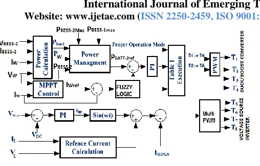
289 Figure 3 Control systems for the proposed hybrid system
Moreover, adjusting the power of the BESS-2 and accomplishing the MPPT of the wind source cause to regulate these duty ratios, so the switching signals of the proposed boost converter are achieved. In the AC side of the proposed system, in order to inject input DC powers along with the reactive and harmonic components of the load current to the grid, the control system requires an accurate reference current waveform. So the inverter of the HDGS produces a current as close as possible to the reference waveform. This reference current waveform is calculated as follows and injected to the grid by PWM
control scheme by comparing load voltage(VL)and load
current(IL). If the grid voltage and load current are
considered as follow,
V
ac=V
msin(
t) (1)
IL(t)=Imsin(t)+Ih+q
(2)
The load compensation current can be calculated as:
Ih+q=IL(t)- 2PLsin (t) (3)
Where the (Ih+q) is defined as current components that
remain after subtracting the active current component
(ImSin(ωt) from the iL(t)and PLis the average value of the
load power. Moreover, the amplitude of the active current (I1m) of the total reference current is obtained from the DC link controller as follow:
I1m=Kp(VDCref -VDC)+Ki (4)
So, the total reference current is obtained as:
Iref=Ih+q+I1(t) = [IL(t) - sin (t)] + I1msin(t) (5) The Four possible operation modes can be defined for
[image:3.612.49.303.94.257.2]the converter. Considering maximum available Wind power, maximum deliverable BESS power, load power and battery charging necessity, proper operation mode is determined by fuzzy logic control scheme.
TABLE I
VARIOUS POWER OPERATION MODES OF SYSTEM
POWER MANAGEMENT OPERATION MODE
CHOSEN DUTY RATIO
Only WT D1
Only BESS-2 D2
WT+BESS-2 D1&D2
WT+BESS-1 discharging D4 WT+BESS-2+BESS-1 discharging D2&D4 BESS-2 discharging+BESS-1 charging D3 WT+BESS-2+BESS1 charging D1&D3
In the normal operation mode, the hybrid system penetrates as much power into the grid as the wind turbine and BESS-2 generate by DC link voltage control. In the power dispatching mode the hybrid system generates the power dispatched by a utility operator or commanded by a user for purpose of utility demand management such as peak load shaving and active load control .In power averaging mode, the hybrid system mitigates fluctuating power generated from the wind turbine and injects more stable (less fluctuating) power output into the grid. The wind turbine operates under variable speed control and MPPT control. Respectively, to produce the maximum energy from varying weather conditions such as wind speed. BESS charges a certain portion of generation from the wind sources or discharges energy stored in the battery. The grid interface inverter regulates the common dc link voltage at a constant value in normal operation, and generates the power ordered by a user or dispatched by a utility operator in dispatching mode. In power averaging mode, the power command of the inverter is set as the value averaged by measuring the sum of power generated in the wind turbine and Battery and filtering the measured value with a low pass filter.
IV. SIMULATION RESULTS
International Journal of Emerging Technology and Advanced Engineering
Website: www.ijetae.com (ISSN 2250-2459,ISO 9001:2008 Certified Journal, Volume 3, Issue 3, March 2013)
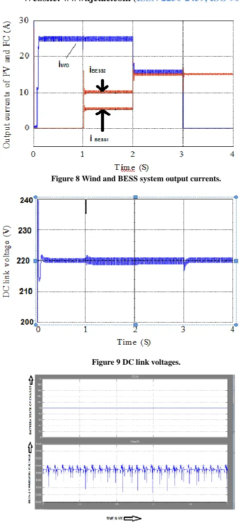
290 This chapter describes the simulation output of BESS-1
charging/Discharging voltage, BESS-2 charging
/Discharging voltages, DC link voltages, and the output voltage of HDGS are shown in the figures below.A grid connected non-linear house hold load with the maximum power of 10Kw (Pf=0.85) is supplied by the system. The grid voltage and load voltage of the system is 220Vrms/50Hz and the load current contains third, fifth and seventh harmonics orders with 60%, 40%, 20% per unit.
A. First simulation stage
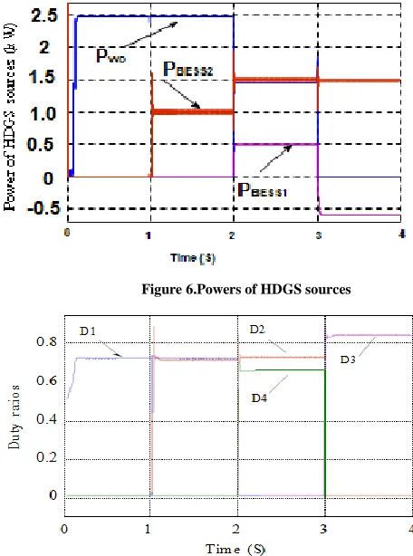
In this stage as shown in the figure 10 and 11, the load
power is PL=1.5Kw while the maximum available wind
power is PW=2.5 Kw (Turbine at 12Rpm).As the Pw> PL in
the first operation mode, there is no need to discharge the battery (BESS).Thus Bess-1 and Bess-2 are charging. The demand power is supplied by the wind turbine. The
maximum power of the wind IW=27.0A and adjusting the
first duty ratio at D1=0.73.As shown in the figure18, the
load current is completely compensated by wind power as well as charging the battery and extra power is injected to the grid.
B. Second Simulation stage
In this stage as shown in the figure 12 and 13, the load
power is constant (PL=1.5Kw). Here discharging of Bess-2
is essential because wind power does not exist. In the
Second operation mode,PBESS-2=1.5Kw is chosen to supply
the load power and Bess-1 is in idle mode. The PBESS-2
current is set on the IBESS-2 = 10 A by adjusting the duty
ratio at D2=0.85.As shown in the Figure 19, the load power
is completely compensated by the BESS-2 and there is no power exchange between the HDGS and the grid.
C. Third Simulation stage
In this stage as shown in the figure 14 and 15, the load
power is increased to the maximum value PL=3.5 Kw. A
step change in the wind level results to decrease the
available maximum PW power into Pw=1.5Kw (Turbine at
2rpm), the load remain constant PL=3.5Kw From the
maximum deliverable power of the PBESS2 is not able to
completely supply the power deficiency (2 Kw) thus the remained power should be supplied by the battery
(BESS1). Consider the PBESS-1 maximum deliverable
power the power deficiency (PL- PW-PBESS2) can be supplied
by the PBESS-1, so the fifth operation mode is chosen for
the converter.
In this maximum power point tracking of the wind power and discharging the batteries are accomplished by
regulating the PW current at IW=10 A and adjusting the first
duty ratio at D1=0.73, while the maximum power of the PBESS-1 is delivered at IBESS-1=2A with adjusting the second duty ratio at D4=0.66. As shown in the figure 20, the load current is completely compensated by combined energy of wind turbine,BESS1 and BESS2.The grid current does not have considerable amplitude.
D. Fourth Simulation stage
In this stage as shown in the figure 16 and 17, since PW
power not exist (for example at unseasonal period) the
demand power PL=3Kw and charging of the battery BESS1
is essential, sixth operation mode is chosen. In this stage,
the maximum power of the PBESS-2 is extracted and the
battery is charged while the deficiency power is provided
by the grid. The current of PBESS-2 is IBESS-2=10 A, the grid
current is out of phase with grid voltage. Which is
regulated by the duty ratio D3=0.85.As shown in the figure
[image:4.612.326.554.382.689.2]21, absorption of deficient power of HDGS from the grid takes place in the sixth operation mode.
Figure 6.Powers of HDGS sources
International Journal of Emerging Technology and Advanced Engineering
Website: www.ijetae.com (ISSN 2250-2459,ISO 9001:2008 Certified Journal, Volume 3, Issue 3, March 2013)
[image:5.612.50.289.112.638.2]291 Figure 8 Wind and BESS system output currents.
Figure 9 DC link voltages.
Figure 10 BESS-1 states of charge and charging voltage
[image:5.612.339.548.284.605.2]
Figure 11 BESS-2 states of charge and charging voltage
Figure 12.BESS-1 in idle mode
International Journal of Emerging Technology and Advanced Engineering
Website: www.ijetae.com (ISSN 2250-2459,ISO 9001:2008 Certified Journal, Volume 3, Issue 3, March 2013)
[image:6.612.62.275.117.262.2]292 Figure 14.BESS-1 state of charge and discharging voltage
[image:6.612.333.554.125.278.2]
Figure 15.BESS-2 state of charge and discharging voltage
[image:6.612.63.275.290.453.2]
Figure 16.BESS-1 state of charge and charging voltage
Figure 17.BESS-2 state of charge and discharging mode
Figure 18.HDGS output current, load current, and the grid voltage (with the scale of 0.064) and current in the first simulation
stage.
Figure 19.HDGS output current, load current, and the grid voltage (with the scale of 0.064) and current in the second simulation
[image:6.612.328.568.446.641.2]International Journal of Emerging Technology and Advanced Engineering
Website: www.ijetae.com (ISSN 2250-2459,ISO 9001:2008 Certified Journal, Volume 3, Issue 3, March 2013)
293 Figure 20.HDGS output current, load current, and the grid
[image:7.612.51.296.133.359.2]voltage (with the scale of 0.064) and current in the third simulation stage.
Figure.2 1 HDGS output current, load current, and the grid voltage (with the scale of 0.064) and current in the fourth simulation
stage.
V. CONCLUSION
This paper proposed a unified structure of multi-input DC Boost converter for hybrid distributed generation system (HDGS) connected to the grid. The proposed converter is supplied by different DG sources such as Wind Source and Battery energy storage system (BESS).
When the wind power is high, it supply the load demand and the extra power is injected to the grid. Due to rapid dynamic response and high efficiency, battery is used as a supplementary power source to supply the load demand. Thus the maximum power from Wind energy/Battery is extracted by independent control of the duty ratios and compensates the load/grid power quality issues using HDGS.
REFERENCES
[1 ] S. H.Hosseini, S.Danyali, F. Nejabatkhah, S.A.Kh. Mozafari Niapoor,,Member, IEEE, “Grid-Connected Three-Input PV/FC/Battery Power System”,2011, IEEE Electrical Power & Energy Conference.
[2 ] Joanne Hui*, IEEE Student Member, Alireza Bakhshai, IEEE Senior Member, and Praveen K. Jain, IEEE Fellow,” A Hybrid Wind-Solar Energy System: A New Rectifier Stage Topology”, Downloaded on June 11,2010 at 13:17:03 UTC from IEEE Xplore. [3 ] K. Narender Reddy and Vivek Agarwal, Senior Member, IEEE,”
Utility-Interactive Hybrid Distributed Generation Scheme With Compensation Feature”, IEEE Transactions On Energy Conversion, Vol. 22, No. 3, September 2007.
[4 ] KeJin, Member, IEEE, Xinbo Ruan, Senior Member, IEEE, Mengxiong Yang, and Min Xu “A Hybrid Fuel Cell Power System” IEEE Transactions on Industrial Electronics, Vol. 56, No. 4, April 2009.
[5 ] Yaow-Ming Chen, Senior Member, IEEE, Yuan-Chuan Liu, Shih-Chieh Hung, and Chung-Sheng Cheng, “Multi-Input Inverter for Grid-Connected Hybrid PV/Wind Power System”, IEEE Transactions On Power Electronics, Vol. 22, No. 3, May 2007. [6 ] Farzam Nejabatkhah, Member,IEEE, Saeed Danyali, Seyed
Hossein Hosseini,Member IEEE,Mehran Sabahi and Seyedabdolkhalegh, Moaffari Niapour, Member,IEEE,” Modeling and Control of a New Three-Input DC-DC Boost Converter for Hybrid PV/FC/Battery Power System”.
[7 ] E.K.Hussain, Student Member, IEEE,C.M Bingham, Member, IET and D.Stone, Member, IET “ Grid connected PVs & Wind Turbine with a Wide Range of Reactive Power Control and Active Filter Capability”,2010.
[image:7.612.49.293.313.468.2]