© 2017, IRJET | Impact Factor value: 5.181 | ISO 9001:2008 Certified Journal
| Page 816
Structural Analysis and Optimization of Buckling Strength through
Stiffeners and Thickness Variation of Vacuum Chamber
Prashant Nadagoud
1, Prof.P.S.Patil
21
M.Tech (Machine Design), B.L.D.E.A’s V. P. Dr.P.G.H College of Engineering and Technology,
Vijayapur, Karnataka, India
2
Asst. Professor, Dept. of Mechanical Engineering, B.L.D.E.A’s V. P. Dr.P.G.H College of Engineering and Technology,
Vijayapur, Karnataka, India
---***---Abstract -
Pressure vessels are widely used in differentindustries, such as gas and petroleum. They may get out of service due to many reasons. However, small cracks on their surface may lead to their operation to be stopped, and their need to being repaired. Therefore, the study of the cracks so as to determine if they could continue their operation despite of their flaw or otherwise is of a great consequence. In this study we investigated the thickness variation of vacuum chamber, hoops stress and buckling strength of a semi elliptical crack on a thin wall spherical pressure vessel under different internal pressures as well as different crack lengths. The simulation was done using ANSYS Software Sub-model method. We do numerical and analytical analysis, and compared the results. The good compatibility between the numerical and analytical results for the thickness variation of vacuum chamber, hoops stress and buckling strength.
Key Words:
Pressure vessel, Vacuum chamber, Bucklingstrength, Hoops stress.
1. INTRODUCTION
Tanks, vessel and pipelines that carry, store or receive fluids are called pressure vessel. A pressure vessel is defined as a container with a pressure differential between inside and outside. The inside pressure is usually higher than the outside. The fluid inside the vessel may undergo a change in state as in the case of steam boiler or may combine with other reagent as in the case of chemical reactor. Pressure vessel often has a combination of high pressure together with high temperature and in some cases flammable fluids or highly radioactive material. Because of such hazards it is imperative that the design be such that no leakage can occur. In addition vessel has to be design carefully to cope with the operating temperature and pressure.
Pressure vessels are widely used in different industries, such as gas and petroleum. They may get out of service due to many reasons. However, small cracks on their surface may lead to their operation to be stopped, and their need to being repaired.
Pressure vessels are usually spherical or cylindrical with dome end. The cylindrical vessels are generally preferred because of the present simple manufacturing problem and
make better use of the available space. Boiler, heat exchanger, chemical reactor and so on, are generally cylindrical.
2. METHODOLOGY
2.1 BASIC STEPS IN FEM
Preprocessing: The Preprocessing is the 1st step in the FEM It consists of defining model geometry, what type element it is and divide the geometry into element. Then define the physical characteristics of the elements. The size of the element must be fixed and between the elements connectivity is established, this process is known as meshing. Then boundary conditions are specified. Then apply the loads on the form.
Solution: In this process, equations are generated in matrix form and are of algebraic. For values of unknown field variables the matrices are solved. As soon as the primary field variables are known as the derived variables forces, stresses are calculated
Post processing: The results obtained are analyzed, and is known as post processing. This step involves sorting of the results. In this stage the required results are sorted and evaluated. The last task of print and presentation of results takes place in this phase.
2.2 Calculation of hoops stress and critical buckling load
Hoops stress
Hoops Stress =
Where, p=differential pressure, atmospheric pressure as internal pressure is zero
d = internal diameter, 2700 mm T = Thickness, 13 mm
Therefore,
© 2017, IRJET | Impact Factor value: 5.181 | ISO 9001:2008 Certified Journal
| Page 817
Critical buckling loadMax external pressure that can be sustained
= Applied Pressure X Load multiplying factor = 0.101 MPa X 2.3803
= 0.2404 MPa
2.3 Material Properties
The material used for the modelling of the pressure vessel is structural steel. Which is linear elastic isotropic material. The density of the material used is 7800 kg/m3, Young’s modulus of the material is 200GPa and Poisson’s ratio of the material is 0.3.
Table 1: Material properties
Case 1: Original Geometry (without stiffeners and
thickness variation)
The thickness of the cylinder taken is t = 13 mm
2.4.1 Modelling of pressure vessel having cylinder
thickness 13mm in CATIA
The pressure vessel is modelled in a CATIA software.
Different parts of pressure vessels aremodelled individually
[image:2.595.309.554.180.352.2]and are assembled in CATIA assemble environment.
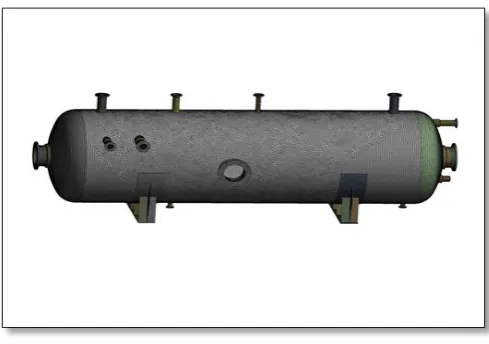
[image:2.595.38.287.307.375.2]Figure 1 shows the model of pressure vessel having thickness 13mm in CATIA
Figure 1: Model of pressure vessel having thickness 13mm in CATIA
Meshing of the pressure vessel
The pressure vessel modelled in a CATIA is converted into step file and is imported into ANSYS workbench to carry out
the different analysis. Then the imported model is meshed in the ANSYS using mesh tool. The sizing for meshing the model is given manually the mesh size is given is 100mm by this the model is meshed finely.
Figure 2 shows meshing of the pressure vessel
Figure 2: Meshing of the model of pressure vessel in ANSYS
Boundary conditions and loading
The pressure vessel has a base and the base is fixed other parts of the vessels motion is constrained in all directions i.e. motion in x, y and z directions are constrained. The pressure is applied internally inside the pressure vessel i.e. 1 10-14 MPa. The atmospheric pressure taken to be 0.101 MPa
The figure 3 shows the boundary conditions and loading on the pressure vessels
[image:2.595.309.559.526.709.2] [image:2.595.35.290.560.681.2]© 2017, IRJET | Impact Factor value: 5.181 | ISO 9001:2008 Certified Journal
| Page 818
[image:3.595.40.285.140.319.2]Pre-stresses Buckling of pressure vessel of original
geometry
Figure 4: Pre-stresses Buckling of pressure vessel of original geometry
Hoops stress for pressure vessel of original
geometry
Figure 5 shows the hoops stress for pressure vessel of original geometry. It can be seen from the figure that the hoops stress obtained is 10.22MPa. The hoops Stress is calculated to be 10.5Mpa which is in the acceptable range as obtained in finite element analysis 10.22 MPa
Figure 5: Hoops stress for pressure vessel of original geometry
Case 2: One stiffener at center
2.4.2 Modelling of pressure vessel with one
stiffener at center in CATIA
The pressure vessel is modelled in a CATIA software. Different parts of pressure vessels are modelled individually and are assembled in CATIA assemble environment while assembling the parts one stiffener is added to the pressure vessel as shown in the figure
Boundary conditions and loading on the pressure
vessel with one stiffener at center
The pressure vessel has a base and the base is fixed other parts of the vessels motion is constrained in all directions i.e. motion in x, y and z directions are constrained. The pressure is applied internally inside the pressure vessel i.e. 1 10-14 MPa. The atmospheric pressure taken to be 0.101 MPa
[image:3.595.308.563.244.420.2]The figure 6 shows the boundary conditions and loading on the pressure vessel with one stiffener at center
Figure 6: Boundary conditions and the loading on the pressure vessel with one stiffener at the center
[image:3.595.43.281.472.602.2]Pre-stresses Buckling of pressure vessel with one
stiffener at center
[image:3.595.305.554.507.683.2]© 2017, IRJET | Impact Factor value: 5.181 | ISO 9001:2008 Certified Journal
| Page 819
Case 3: One stiffener at center with saddle
2.4.3 Modelling of pressure vessel having one
stiffener at center with saddle in CATIA
[image:4.595.37.284.229.391.2]The pressure vessel is modelled in a CATIA software. Different parts of pressure vessels are modelled individually and are assembled in solid edge assemble environment while assembling the parts one stiffener and CATIA added to the pressure vessel as shown in the figure
Figure 8: Boundary conditions and the loading on the pressure vessel having one stiffener with saddle at the
center
Pre-stresses Buckling of pressure vessel having one
stiffener at center with saddle
Figure 9: Pre-stresses Buckling of pressure vessel having one stiffener at center with saddle
Case 4: Cylinder thickness variation (1)
The thickness of the cylinder taken is t = 18 mm
2.4.4 Modelling of pressure vessel having cylinder
thickness 18 mm in CATIA
The pressure vessel is modelled in a CATIA software. Different parts of pressure vessels are modelled individually and are assembled in CATIA assemble environment.
Boundary conditions and loading on the pressure
vessel having cylinder thickness 18mm
The pressure vessel has a base and the base is fixed other parts of the vessels motion is constrained in all directions i.e. motion in x, y and z directions are constrained. The pressure is applied internally inside the pressure vessel i.e. 1 10-14 MPa. The atmospheric pressure taken to be 0.101 MPa
[image:4.595.309.561.326.494.2]The figure 10 shows the boundary conditions and loading on the pressure vessel having cylinder thickness 18mm
Figure 10: Boundary conditions and the loading on the pressure vessel having cylinder thickness 18mm
Pre-stresses Buckling on the pressure vessel
having cylinder thickness 18mm
[image:4.595.37.282.484.668.2] [image:4.595.308.554.574.744.2]© 2017, IRJET | Impact Factor value: 5.181 | ISO 9001:2008 Certified Journal
| Page 820
Case 5: Cylinder thickness variation (2)
The thickness of the cylinder taken is t = 20 mm
2.4.5 Modelling of pressure vessel having cylinder
thickness 20 mm in CATIA
The pressure vessel is modelled in a CATIA software. Different parts of pressure vessels are modelled individually and are assembled in CATIA assemble environment.
Boundary conditions and loading on the pressure
vessel having cylinder thickness 20mm
The pressure vessel has a base and the base is fixed other parts of the vessels motion is constrained in all directions i.e. motion in x, y and z directions are constrained. The pressure is applied internally inside the pressure vessel i.e. 1 10-14 MPa. The atmospheric pressure taken to be 0.101 MPa
[image:5.595.35.284.369.521.2]The figure 12 shows the boundary conditions and loading on the pressure vessel having cylinder thickness 20mm
Figure 12: Boundary conditions and the loading on the pressure vessel having cylinder thickness 20mm
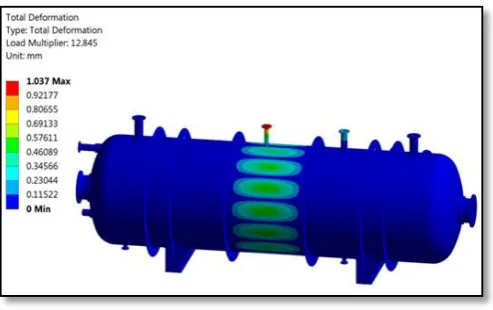
Pre-stresses buckling of pressure vessel having
cylinder thickness 20 mm
Figure 13: Pre-stresses buckling of pressure vessel having cylinder thickness 20 mm
Case 6: Four stiffeners with Saddle
2.4.6 Modelling of pressure vessel having four
stiffeners with saddle in CATIA
The pressure vessel is modelled in a CATIA software. Different parts of pressure vessels are modelled individually and are assembled in CATIA assemble environment while assembling the parts four stiffeners and saddle are added to the pressure vessel.
Boundary conditions and loading on the pressure
vessel having four stiffener with saddle
The pressure vessel has a base and the base is fixed other parts of the vessels motion is constrained in all directions i.e. motion in x, y and z directions are constrained. The pressure is applied internally inside the pressure vessel i.e. 1 10-14 MPa. The atmospheric pressure taken to be 0.101 MPa
[image:5.595.308.555.371.517.2]The figure 14 shows the boundary conditions and loading on the pressure vessel having four stiffener with saddle
Figure 14: Boundary conditions and loading on the pressure vessel having four stiffener with saddle
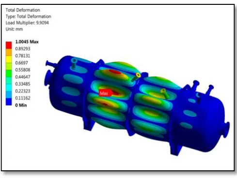
Pre-stresses buckling of pressure vessel of having
four stiffeners with Saddle
[image:5.595.310.557.598.753.2] [image:5.595.37.287.602.758.2]© 2017, IRJET | Impact Factor value: 5.181 | ISO 9001:2008 Certified Journal
| Page 821
CONCLUSIONS
• The results show that the effect of change in
thickness is less effective than adding the stiffeners
• The buckling strength is improved as we add
stiffeners
• Adding stiffeners will give advantage in preventing
crack growth
• A non-linear buckling analysis can be performed in
future scope
REFERANCES
1. Apurva R. Pendbhaje, Mahesh Gaikwad, Nitin Deshmukh and Rajkumar Patil 2011 Design and Analysis of Pressure Vessel. International Journal of Innovative Research in Technology & Science(IJIRTS) ISSN:2321-1156
2. Mr. Abdul Sayeed AW Shaikh and Prof. P.T.Nitnaware 2013 Finite Element Analysis & Thickness Optimization of Vacuum Chamber for Electron Microscopy Applications. International Journal of Modern Engineering Research (IJMER) Vol. 3, ISSN: 2249-6645 (June).
3. Mahesh S. Ghule and Dr.R.S.Bindu 2016 Design, Development & Analysis of Vacuum Chamber of Potting Machine. International Journal of Scientific Engineering and Technology Research. Vol.05, ISSN 2319-8885 (July)
4. Maheshkumar G. and Menon Rekha Ravindra 2017 Design of vacuum impregnation chamber for soaking of Gulabjamun in sugar syrup and optimization of wall thickness by Finite Element Analysis (FEA). International Journal of Environment, Agriculture and Biotechno logy (IJEAB) Vol-2, ISSN: 2456-1878(Jan-Feb).
[5] B.S.Thakkar, S.A.Thakkar; “DESIGN OF PRESSURE VESSEL USING ASME CODE, SECTION VIII, DIVISION 1”; International Journal of Advanced Engineering Research and Studies, Vol. I, Issue II, January-March, 2012
[6] ASME Boiler and Pressure Vessel Code 2007 Sec 8 Division 1 (2007).
[7] WANG Wenlong, CAI Guobiao, ZHOU Jianping “ Large-Scale Vacuum Vessel Design and Finite Element Analysis” Chinese Journal of Aeronautics 25(2012) 189-197.