© 2017, IRJET | Impact Factor value: 5.181 | ISO 9001:2008 Certified Journal
| Page 813
“DESIGN, SIMULATION AND OPTIMIZATION OF MULTITUBUBLAR
ROLLCAGE OF AN ALL TERRAIN VEHICLE”
PRAKHAR AGARWAL
1, NITISH MALIK
2, SHUBHAM KUSHWAH
31,2,3
Department of Automobile Engineering, Rustamji Institute of Technology, Tekanpur BSF Academy, M.P. India
---***---Abstract – Roll cage is the frame that is used as a3-dimensional protected space around the driver that will keep the driver safe especially when the vehicle rolls over. This paper is based on the static analysis and optimization of a Roll cage of a single seated vehicle in off road conditions using various pipe cross section. The objective of this work is to design of pertinent roll cage to be installed on a BAJA vehicle by keeping the frame weight low and having enhanced ergonomics that is comfortable and safe with adequate structural strength and stiffness along with other subsystems compatibility. It is done on using ANSYS 15.0 software. Three dimensional solid model of a roll cage is created using SOLIDWORKS 14.5 software. Detailed description of material is provided, finite element meshing is done, the load condition is worked out and the boundary conditions are given. The responses of the Roll cage which includes the stress distribution and the displacement under various loading condition are observed
Keywords – ANSYS 15.0, displacement, Ergonomics, Roll Cage, Static Analysis, Von-Mises stress..
1. INTRODUCTION
Roll cage is the frame that is used to protect the rider when the vehicle rolls over. It is generally made of thin gauge pipes welded together to make a structure called cage. Roll cage is generally employed in car racing for additional protection of driver. When the car flips upside down, roll cage protects the roof of car from crushing down and prevents the rider from getting stuck inside crushed metal. Roll cage provides additional strength to the car body frame and provides better safety. Ergonomics is the process of designing or arranging things, so that people can
use them easily and safely. BAJA SAEINDIA is a competitive
platform for engineering students that introduces the real
world engineering design problems. In this annual
motorsport event which allows to think differently on various critical problems that are faced during designing and manufacturing of the vehicle. Material for the roll cage is selected such that it keep the weight of the vehicle low and without compromising necessary strength. This frame has to be designed in the way to absorb the kinetic energy during impacts reducing the risk of injuries for drivers and navigators. The roll cage is designed to carry a person height 190cm (75 in) tall, weighing 113kg (250lbs) & along with that incorporate all the vehicle sub-systems. A 3-D software model is prepared in Solid works 14.5. Later the
design is tested against all modes of failure by conducting various simulations and stress analysis with the help of ANSYS 15.0. Based on the result obtained from these tests the design is modified accordingly. After successfully designing of roll cage, it is fabricated.
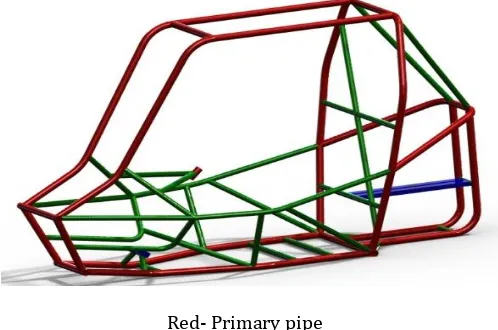
Since the chassis weight consideration is the main part of an automotive, it should be strong and light weight. Thus, the chassis design becomes very important. Typical capabilities on basis of which these vehicles are judged are hill climbing, pulling, acceleration and manoeuvrability on land as well as shallow waters. This is aimed to design the frame of an ATV which is of minimum possible weight and show that the design is safe, rugged and easy to manoeuvre. Design is done and carried out linear static analysis for the frame.
[image:1.595.315.564.411.576.2]Red- Primary pipe Green - Secondary pipe
Fig. 1 Rollcage made in Solidwork
1.1. THEORY
1.1.1. Static Analysis
© 2017, IRJET | Impact Factor value: 5.181 | ISO 9001:2008 Certified Journal
| Page 814
components caused by loads that do not induce significantinertia and damping effects.
1.1.2. Von-Mises Stress Analysis
The Von Mises stress is often used in determining whether an isotropic and ductile metal yield when subjected to a complex loading condition. This is done by calculating the Von Mises stress and comparing it to material’s yield stress, which constitutes the Von Mises Yield Criterion. It is an empirical process, with inherent error and deviations. The defining equation for the von Mises stress was first proposed by Huber in 1904. It was proposed again by von Mises in 1913. In 1924 Hencky recognized that von Mises stress was actually related to deviatoric strain energy [10]. The equation of von Mises stress is given as
An engineer's duty is to keep the maximum value of Von Mises stress induced in the material less than its strength or yield stress, such that, the design becomes a safe design.
2 PROBLEM DEFINITION
The design and development process of the roll cage involves various factors; namely material selection, frame design, cross-section determination and finite element analysis. One of the key design decision of our frame that greatly increases the safety, reliability and performance in any automobile design is material selection. To ensure that the optimal material is chosen, extensive research was carried out and compared with materials from multiple categories. The key categories for comparison were strength, weight, and cost. Here we are going design the chassis for two materials namely AISI Steel 1018 and 4130 Chrome moly steel.
3. RESEARCH METHODOLOGY
3.1Design Methodology
As designing of roll cage is the most important parameter which influence the overall performance of vehicle are highly concern about design selection.
3.1.1 Design considerations:
While designing the roll cage, various design concerns are followed that further improves the structural rigidity also. These are discussed below:
• BAJA SAE rules.
• Driver’s comfort and safety. • Subsystem compatibility.
• High structural strength and stiffness. • Serviceability & manufacturability.
Fig2. Side view of rollcage
Fig3. Front view of roll cage
Fig4.Driver Ergonomics in CATIA V5 R19
© 2017, IRJET | Impact Factor value: 5.181 | ISO 9001:2008 Certified Journal
| Page 815
reduce manufacturing costs. The finalize roll cage givingbest performance results with taking above principles as our main objectives. For validation of its ergonomics firstly construct prototype of PVC pipes and then analyses it by using ANSYS 15.0 .
3.1.2 Material Selection
One of the key design decisions of our frame that greatly increases the safety, reliability and performance in any automobile design is material selection. To ensure that the optimal material is selected through extensive research and compared with materials from multiple categories. The key categories for comparison were strength, weight, and cost. 1018 steel, and 4130 chromoly were first considered. In general, the design of mini all terrain vehicles, if the standard tube size of 25.4×3 mm is not used, then the material has to have equivalent bending strength to that of 1018 steel in the standard tube size.
By considering the above constraints use various cross section of the pipe i.e. 25.4×3 mm, 28.57×1.65 mm, & 31.75×1.65 mm the following selection based on the availability in the market. After this, calculate the bending strength & bending stiffness of the selected cross sections of the pipe.
From the calculation select 31.75×1.65 mm since it providing the maximum bending strength & bending stiffness & also having low weight among the selected cross sections.
Parameters AISI 1018 AISI 4130 Outer Diameter 25.4 mm 31.75 mm Wall Thickness 3 mm 1.65 mm Bending
Strength 365 N-m 805.64 N-m
Bending
Stiffness 2763.12 Nm
2 3628.5 Nm2
Yield Strength 365MPa 733 Mpa
Table1. Comparison of parameters between AISI1018 Vs AISI 4130
3.2Calculation of Bending strength and bending stiffness
3.2.1Second moment of inertia
I = π/64(Dout4-Dinner4)
Where,
Dout= Outer Diameter of a pipe =31.75 mm
Dinner= Inner Diameter of a pipe =28.45 mm
= π/64 ((31.75)4-(28.45)4
= 17723.37 mm4
3.2.2Young’s Modulus
E = 205 GPa
3.2.3Yield Strength
Sy = 733 MPa
3.2.4 Distance between neutral axis and extreme fibre
C = 15.875 mm
3.2.5 Bending Strength
= SyI/C
=733×106×17723.37×10-12/15.87×10-3
= 805.64 N-m
3.2.6 Bending Stiffness
= E×I
= 17723.37× 10-12×205×109
Bending stiffness =3628.5 N-m2
3.3 Analysis of various pipe cross section
Poisson's Ratio 0.33 Elastic Modulus (GPa) 205 Tensile Strength (MPa) 841 Yield Strength (MPa) 733 Elongation (%) 28.2
Table2. Mechanical properties of AISI 4130
© 2017, IRJET | Impact Factor value: 5.181 | ISO 9001:2008 Certified Journal
| Page 816
Graph2. Bending Strength v/s Wall Thickness4.FINITE ELEMENT ANALYSIS
4.1Meshing, Constraints and Boundary Conditions:
FEA is very powerful tool which enables us to solve various real world engineering problems. But FEA will only be helpful when it is done under specified FEA rules. Mesh quality is one of them. Great attention has been given to improve mesh quality. Static structural analysis has been done in ANSYS workbench 15.0. 2D uniform quad is selected as mesh element. Meshing has been done using various element sizes from 8 mm – 2 mm in which 4 mm is selected based on Aspect ratio, Jacobian ratio and Warpage factor.
Fig2. Mesh quality
Fig3. Aspect Ratio at various element size
Load cases for simulation:
Conditions Force
applied Fixed
Front crash 16875 N H-arm mounting and link Rear crash 12375 N A-arm mounting and tie
rods
Side crash 10800 N Suspension mounts Roll over 4500 N Suspension mounts Torsional
stiffness 1462.5 N H-arm mounts Drop test 3825 N &
5850 N Suspension mounts
Table3. Various load cases
4.2 Analytical calculation for different crash
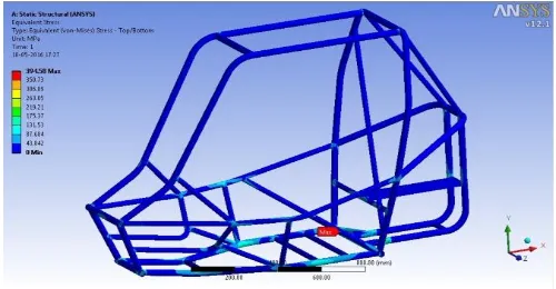
4.2.1 Front crash
The front impact analysis is done for analyzing the rigidity of a roll cage as well as the safety of the driver in case of a head on collision of the car.
The force is applied on the front part of the vehicle (nose) and fixing suspension pick up points.
Let the velocity of our vehicle is 50km/hr=13.89m/s. Suddenly, within 0.2 sec it strikes with a rigid wall then the deceleration of the vehicle.
v= u + at
0=15m/s + a ×0.2sec a=75 m/s2
Mass of buggy with driver = 250 kg
So force of impact F= m × a = 250 × 75
= 18750 N
[image:4.595.314.564.583.713.2]7.5G force is applied.
© 2017, IRJET | Impact Factor value: 5.181 | ISO 9001:2008 Certified Journal
| Page 817
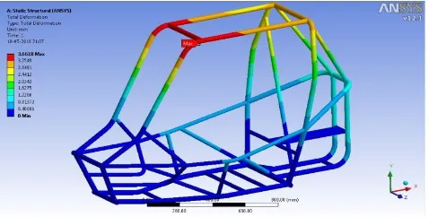
Fig 5 Deformation in front crash4.2.2Rear crash
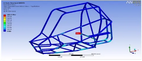
The rear impact analysis is done for analyzing the rigidity of a roll cage in case of a collision of the vehicle from back side when some another car hits.
The force is applied on the rear part of the vehicle and fixing suspension pick up points.
Let our vehicle is stationary & another vehicle strikes it from backwith 40 km/hr, similarly the deceleration of the vehicle.
v= u + at
0=11.11m/s + a ×0.2sec a= 55.55 m/s2
Now, force of Impact F = m × a
= 250kg ×55.55 m/ = 13887 N.
[image:5.595.316.561.346.482.2]5.5 G force is applied
Fig. 6 Stress generation in rear crash
Fig. 7 Deformation in Rear crash
4.2.3Side crash
Side impact analysis of a buggy is done to check the strength of the roll-cage in the case of accident involving the vehicle hit by another car from side.
The force is applied on the side most members of the vehicle and fixing suspension pick up points.
Suppose our vehicle is stationary & a another vehicle with 30km/hr =9.72m/s strike us from side then, deceleration
V= u + at 0= 9.72 + a × 0.2 a = 48.6 m/s2
So, force of Impact F = m × a
=250 kg ×48.6 m/ =12150 N
[image:5.595.37.277.496.600.2]4.8 G force is applied
Fig. 8 Stress generation in side crash
Fig 9 Deformation in side crash
4.2.4Torsional rigidty
[image:5.595.316.564.515.648.2] [image:5.595.39.278.634.734.2]© 2017, IRJET | Impact Factor value: 5.181 | ISO 9001:2008 Certified Journal
| Page 818
at suitable locations on roll cage after the analysis wasdone.
For this we have done,
The weight distribution of our vehicle is 60:40 (Rear : Front) So ,Force transfer from rear to front after the application of brake at bump is 60% of the total weight.
So weight on the front axle F=0.60 ×250 ×9.81 =1471.5 N
A couple is generate which tries to twist the roll cage so, 1471.5 N force is applied on four mounting points of wishbone that is 367.6 N on each mounting point.
A couple is created by four force in upward direction & four downward direction.
Let us suppose the forces of couple are acting on the mean of nose
Length. i.e. 360 + 300 = 330
K=T/ tan = P/B
tan = Deflection /1/2 ×( mean of nose length) tan =2 ×3.62/330
=tan-1 7.24/330
= tan-1 0.02 and hence = 1.14
Now, for torque
Our Front track width is 125 cm
So, applied torque on front section of our rollcage is T=F ×1/2( track width)
=1471.5 N × 0.625 m =974.375 N-m
So, the torsional stiffness of our rollcage is K=T/ =974.3/ N-m =974.3/1.14
=854.6 N-m
[image:6.595.330.544.98.208.2]Fig.10 Stress generation in torsional rigidity
Fig. 11 Deformation in Torsional rigidity
4.2.5Drop test
Let us assume that our vehicle is dropped from 1m height and let the time of impact is 0.1 sec
Now, from Newton Second Law of Motion
F = { 40% mass = 0.40 250=100 kg } =d (mv) / dt
= mdv/dt = 100 × 4.42/0.1= 4420 N
Therefore , force on each damper mounting (front) = 2210 N
Similarly for rear side,
60% mass of our vehicle is 0.60 250 = 150kg F=150 ×4.42/0.1 =6630 N
[image:6.595.39.550.272.735.2]Therefore force on each damper mounting (rear) = 2215 N
Fig. 12 Stress generation in drop test
[image:6.595.325.546.475.584.2]© 2017, IRJET | Impact Factor value: 5.181 | ISO 9001:2008 Certified Journal
| Page 819
4.2.6Rollover TestSince it is an All-Terrain Vehicle the buggy is vulnerable to the conditions of rollover.
We had considered front roll over, the vehicle is considered as toppling while descending down a gradient or hill.
For this, force is applied on 45 degree at FBM–
[image:7.595.328.570.231.331.2]RHO bends of the vehicle and fixing suspension pick up points.
[image:7.595.321.558.376.535.2]Fig. 14 Stress generation in front rollover
Fig, 15 Displacement in rollover test
5. RESULTS:
The synopsis of the problem is represented here in the form of deformed shape and the von- mises stress plotted. The value observed for the deformed shape and are within the permissible limits. The weight of BAJA 2016 buggy was 230 kg and weight of BAJA 2017 buggy is 162 kg reducing weight upto 30 %.
6. CONCLUSION:
This paper has illustrated the entire design methodology of roll cage and understand the indispensable components of designing. Safety and ergonomics are today’s utmost concern in every respect; for the driver, crew & environment. Considerable factor of safety (FOS) or design factors is applied to the roll cage design to minimize the risk of failure & pertinent resulting injury. This optimized
FOS value implies the safe value of applied loads and deformations.
After optimization the above roll cage there is a splendid increase in the performance of the vehicle and we implemented without any failure. Our goal is to design a lightweight rollcage much more compact and better in strength perspectives. The fatigue life of the components seems to be effectively high. This rollcage is easy to assemble and disassemble. This is used in the motorsport event BAJA SAE INDIA 2017 vehicle by the Team Benign Beaders.
Table4. FOS in different load cases
Fig16. Exploded view of BAJA Vehicle
Fig.17 BAJA vehicle used in 2017 Motorsport event CONDITIONS MAX.
STRESS(MPa) MAX.DEF (mm) F.0.S. Front crash 394.58 2.760 1.857 Rear crash 310.71 2.086 2.359 Side crash 566.02 3.932 1.295
Torsional 127.47 0.461 5.75
Drop 286.61 0.995 2.557
[image:7.595.39.278.396.517.2]© 2017, IRJET | Impact Factor value: 5.181 | ISO 9001:2008 Certified Journal
| Page 820
7.
REFERENCES:
BAJA SAEINDIA rule book 2016. www.bajatutor.com
http://www.engineeringtoolbox.com/torsion-shafts-d_947.html.
Structural Analysis with Finite Elements by Friedel Hartmann , Casimir Katz
Thomas D. Gillespie. Fundamentals of Vehicle Dynamics. Society of Automotive Engineers, Inc.
Prof. Dipl.-Ing.Jornsen Reimpell. The automotive chassis: engineering principles (2001). Butterworth-Heinemann.
Properties of Carbon steel AISI 1018 & 4130 http://www.efunda.com/materials/alloys/carbon