© 2017, IRJET | Impact Factor value: 5.181 | ISO 9001:2008 Certified Journal | Page 1904
ENERGY GENERATION FROM PELTIER MODULE BY UTILIZING HEAT
Darshak Vadhel
1, Savadas Modhavadiya
2, Prof. Jaydipsinh Zala
31 2
B.E Students, Department of Electrical Engineering, Dr. Subhash Technical Campus- Junagadh, India
3
Professor, Department of Electrical Engineering, Dr. Subhash Technical Campus- Junagadh, India
---***---Abstract-
Availability of electricity in remote areas suchas forests and mountains is always doubtful because of various inconvenience caused by both the location and the atmosphere. Use of unconventional methods such as solar panels and generator when electricity is not reachable through transmission lines always clashes with nature in a way like dense forest areas and noise or air pollution due to generator in these areas so a suitable solution is needed. A device running on solid state devices like a Peltier module can be handy as there is no need of solar rays and it can provide a noiseless energy as per the need with very least use of sources and with less or zero effect on nature. These elements work on the Seebeck effect in which difference between two dissimilar electrical conductors or semiconductors produces a voltage difference between the two substances. Peltier modules can run on the latent heat generated by the candles or campfires and on the other side heat sink or chilled water/ice can be used for heat dissipation. By providing heating on one side and cooling on the other side a temperature difference is created which plays an important role in the voltage generation. Generated voltages can be high or low depending on the needs of the user and number of connected Peltier modules but it can be controlled and stabilized with the help of dc choppers.
Key Words: Peltier module, Thermoelectric energy, Heat utilization, Seebeck effect, Peltier effect
1. INTRODUCTION
Around 1.3 billion people live without electricity in the world and a quarter of them (300 Million) lives in India. Rural and isolated areas happen to be highly affected because of this and it will take a long time before the electricity reaches to them in normal ways through transmission and distribution system.
The remotely isolated areas of forests and mountains do not have the reach to the electricity in many cases and hence an independent source of energy is necessary. The device made from Peltier modules try to provide energy by converting thermal energy into electrical energy. The sources of thermal energy are easily available around this places and their use does not affect the environment in a harmful manner. It is possible to run various devices used for lighting and other needs with the help of this device by converting the generated voltages with the use of various converters such as choppers and inverters.
The key element Peltier module, a thermoelectric module have the ability to convert thermal energy into electrical energy. They are made of two unique semiconductors, one being p-type and another being n-type and they are static in nature. The working operation is based on Seebeck effect (conversion of heat into electricity) which occurs inside the Peltier modules. As the heat spreads and starts flowing so does the free charge carriers from the hot side to the cold side. The end voltages are proportional to the temperature difference and the system keeps on generating voltage as long as the temperature difference remain intact. Generated voltages from each Peltier module increases with respect to time and temperature difference. They are connected in series so that the end voltages will be high. The temperature keeps on changing so instability occurs which may damage the connected equipment so a chopper is connected before connecting the device to the system which provides pure and stable dc voltages.
The device is not only useful for isolated areas but it can also be used in the industrial sector where latent heat is produced which can be used as the source of heating and extra amount of energy can be produced with it.
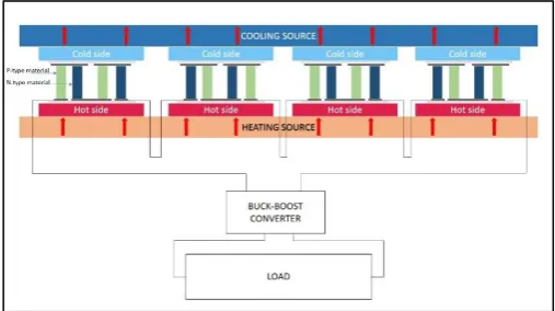
[image:1.595.308.562.507.649.2]2. CONSTRUCTION
Fig 1- Peltier modules connected in series
© 2017, IRJET | Impact Factor value: 5.181 | ISO 9001:2008 Certified Journal | Page 1905
flames or wood as heating source for hot side and chilledwater or ice as cooling source for the cold side also we can use heat sink on the cold side to increase and improve the speed of process.
The core of the device is a significant number of Peltier modules and for general needs around ten Peltier modules are sufficient. They work by essentially moving heat from one side to the other side when heat is applied and the other side is kept cool with a heat sink or chilled water and ice. This generation of electricity is caused by the
temperature difference between two dissimilar
semiconductors causes voltage difference.
A metal tray is also needed to hold the cooling source in case it is water or ice and if the heat sink is used then they are attached to the cold side of the Peltier module and they are large enough to accommodate all the Peltier plates on the base with its printed text being upwards. Thermally conductive glue is used to join them strongly with the base of the cooling source. In the case of using metal tray to store the cooling source, outside walls of the tray are covered by the plastic tapes to prevent shorting and other harms and modules are fixed at the bottom.
The modules are connected in series with each other by connecting the positive (red) and negative (black) of the wires. The opposite wires at the end are left loose as they will be helpful in obtaining the blooming but unstable voltages. End voltages will be high and unstable because of Peltier module being connected in series and gradual change in temperature difference over a period of time hence voltage regulating device-chopper is needed which provides stable and controlled voltages ranging from 5 volts to 35 volts. The regulator happens to be mounted far from the sources of heating and cooling so that it can be protected from heating and shorting. Heating might happen inside the chopper so that heat sink can be attached for proper dissipation of heat. Also to get more heat concentrated equally on the module, a metal plate is used which spreads the heat. To provide external support all the elements are fitted inside a box. Heating, an important phenomenon is provided with the help of byproducts from both the industries and domestic areas and in absence of byproduct, candle flames or woods can be used as the source. It is provided to the Peltier modules which are connected to the cooling source. Cooling can be provided by chilled water or ice storing into a metal tray or heat sink can be fixed with the Peltier modules and use of a
fan to dissipate the heat and provide cooling. This
arrangement starts producing voltage in some time and that too without making any noise. Also, the rigid construction can wield a much and the Peltier modules itself can easily work for a long life span without any failures.
3. WORKING
Fig- 2: Operation inside Peltier module
The Peltier modules are fitted below the cooling source which can be a heat sink and cooling fan or metal tray containing cooling source and they are fitted inside a wooden box. Peltier modules are fixed with the help of thermal grease and their hot side is also covered by a metal plate to spread the heat and protect the Peltier module from the fumes. The process starts with providing cooling source first and then heating source to the Peltier modules. Sometime later, Peltier modules start producing voltages as the thermal energy is converted into electrical energy. The whole operation happens to be noiseless. The generated voltages are in proportion to the number of modules connected to each other in series and also they are dependent on the temperature difference. As soon as heat reaches the Peltier modules, the temperature difference is imposed across them and the heat passing through the device is converted to electrical power.
As heat travels through Peltier module, more power is altered from the heat with an increase in temperature difference and power output also increases. Peltier modules are thermoelectric made from the semiconductive elements Bismuth Telluride and Lead Telluride and in it, some electrons are bound to the nuclei and some are free to move. Being contained with semiconductors, Peltier modules contain charges that can flow from high energy to low energy thus by taking a Peltier module and providing heating and cooling on the opposite surfaces will create temperature difference and then we can get a negative charge on one side and positive charge on the other side, the difference between the charges cause a potential difference which is also known as voltage and it happens to be a measure of electricity.
© 2017, IRJET | Impact Factor value: 5.181 | ISO 9001:2008 Certified Journal | Page 1906
through the inductor will be zero. When the switch isclosed for the first time, blocking diode interrupts current from flowing into the RHS of the circuit, so it mandatorily flows through the passive element inductor. A rapid current change is rare in the inductors, so it keeps the current low by dropping most of the voltages from the source. Gradually, the inductor will let the current to slowly increase by decreasing the voltage drop and at the same time inductor stores energy in the form of magnetic field. Later the energy is released through the diode to the output RC circuit.
4. COMPONENTS
4.1 Peltier Module
A sandwiched shape device which can convert heat energy into electrical energy can be the fundamental introduction of Peltier modules. Working on both the Seebeck effect and the Peltier effect, Peltier modules have the ability to generate voltages or to provide heating or cooling depending on the need of the user.
Fig-3: Peltier module
The construction of the module contains a couple of ceramic plates inside which an array of small bismuth telluride cubes are stored. The charge carriers inside the material and the semiconductors move freely while carrying both charge and the heat. Creating temperature difference causes the carries at hot end to diffuse at the cold end. This buildup of carrier charge at hot end results into a buildup of net charge at the cold end thus resulting in the voltage production. The semiconductors are highly doped by pollutants to increase the electric conductivity. One thing which must be kept in mind while selecting the material for the module is that it must be able to withstand high temperatures. Bismuth Telluride is one of the materials which have the tendency toward the Seebeck effect hence a module made of it produces the voltage. However one must note that they have high electric conductivity and low thermal conductivity. Modules have a very high operating temperature.
4.2 Buck-Boost Converter
Fig-4: Buck-Boost converter
The Buck-Boost converter will step up the voltages produced from the Peltier modules and also it will stabilize them and at the same time current will be stepped down comparing with its input. The Buck-Boost converter includes semiconductors such as diodes and transistors. It also has one of the energy storing elements such as inductor or capacitor. As the Peltier modules have the tendency of unstabilizing voltage because of temperature difference so chances of ripple will be high hence filter made of the capacitor will be added. Later, the load will be connected to the buck-boost converter which allows the device to run smoothly.
4.3 Heating System
Heating, a necessary phenomenon can be provided from the waste heat of industries or heat generated from the various purposes such as cooking in domestic areas. In absence of waste heat, candle fumes or wood can be used as the heating source and they are contained in some metal tray and put below the Peltier modules so that Peltier module’s one side gets hot and to spread the heat equally a metal plate is used to cover hot side equally. Also, hot vapor can be used as a heating source which is an important byproduct in many industries. Different sources provide different temperature to the Peltier modules and also it should be noted that Peltier modules can withstand temperature up to a certain point and after that chances of its damage increases so one must be careful while dealing with the temperature.
4.4 Cooling System
© 2017, IRJET | Impact Factor value: 5.181 | ISO 9001:2008 Certified Journal | Page 1907
we connect many Peltier modules than it cannot provideexpected cooling and in that cases we must use chilled water and ice as the source of cooling.
5.
PERFORMANCE AND EFFICIENCY CALCULATION
The heat is provided to the one side of the module and another side is either connected with the heat sink or something which can dissipate heat such as ice or chilled water is connected to the other part and due to this temperature difference ΔT obtains between two junctions inside the module. The sides of the module are covered by insulated sheaths so heat flows along the length only. This temperature difference due to heat provided on the hot junction causes the electron in the n-type block and the holes in the p-type block to flow from the hot side to the cold side of the module thereby producing an electrical potential difference. The inner circuit completes when a load resistance RL is connected and current starts flowing through this load resistance.
The potential difference occurring between the two junctions can be given by V = α ΔT where α happens to be the Seebeck coefficient and ΔT happens to be the temperature difference between the hot junction and the cold junction. If R is the internal resistance of the system then the current flowing through the load resistance RL can be given by
Substitute the value of voltage in above equation we get current,
We are aware that power flow to external load is given by, PL = I2RL and substituting the value of I
( )
This power will be maximum when internal resistance and load resistance will be same, R=RL and in that case, maximum power can be given by
( )
The term (α2 / R) can be called as a figure of merit and for power to be maximum the temperature difference between the surfaces should be as large as possible. Internal resistance should be as low as possible if we want to harness the maximum power and it can be done by increasing the length and the diameter of the modules. The efficiency of the system can be defined by the ratio of power developed, PL across the load resistance and the heat flow Q, from the source.
( )
6.
GENERAL
PRECAUTIONS
FOR
THE
ARRANGEMENT
To avoid the damage temperature must not exceed
the limit of Peltier modules.
Dropping or exerting mechanical shock on the
Peltier module can cause it to break.
Direct exposure to sunlight and humidity may
damage the Peltier modules.
Peltier modules must have full surface contact
with the heating source. Ideally, distance from flatness should be kept under 0.02 mm.
Thinly spread thermally conductive grease
between the Peltier module surface and the heat exchanger.
Optimum efficiency is not obtained at maximum
voltage or maximum electric current. It is recommended that the voltage and current are set to about 70% of their maximum.
Changing the current polarity rapidly as a method
of modulation shortens the life of the unit hence it must not be adopted.
7. ADVANTAGES AND APPLICATIONS
7.1 Advantages
Portable
No moving or rotating parts
Less maintenance
Operable at elevated temperatures.
Source for the alteration is heat, not light, so day and night operation is possible.
Works in any alteration
It can be used as an alternative power source.
Requires less space and operating cost.
7.2 Applications
DC voltage generation
Waste heat utilization and removal
It can be used in Transportation systems,
Domestic Buildings, Industries, and Power plants.
8. CONCLUSION
© 2017, IRJET | Impact Factor value: 5.181 | ISO 9001:2008 Certified Journal | Page 1908
designed for it. The arrangement provides heating andcooling to the opposite sides of Peltier module. Waste heat, woods or candle fumes can be used as the heating source and chilled water, ice or nitrous oxide can be used as the cooling source. It works on the principle of Seebeck effect according to which temperature difference between two dissimilar semiconductors produces. The generated voltages are proportional to the number of Peltier modules and the temperature difference between the surfaces. Later generated voltages are stabilized with the help of a buck-boost converter. It can be used in remote areas, domestic areas and in industrial areas also.
REFERENCES
[1] G. J. Snyder, “Thermoelectric Power Generation:
Efficiency and Compatibility,” in Thermoelectrics Handbook Macro to Nano, edited by D. M. Rowe (CRC, Boca Raton, 2006), Ch. 9.
[2] M. Kishi, H. Nemoto, T. Hamao, M. Yamamoto, S. Sudou, M. Mandai, and S. Yamamoto, in Eighteenth International Conference on Thermoelectrics Proceedings, ICT’99, 301 (1999).
[3] Thermoelectric generator. (2017, March 14).
Retrieved March 20, 2017, from
https://en.wikipedia.org/wiki/ Thermoelectric_genertor
[4] Meyer, A., & Young, W. H. (1969).
Thermoelectricity and Energy-Dependent
Pseudopotentials. Physical Review, 184(3), 1003-1006. doi:10.1103/physrev.184.1003
[5] Thermoelectricity abstracts. (1961). Advanced
Energy Conversion,1, 191-364. doi:10.1016/0365 1789(61) 90034-0
[6] Rosa, A. D. (2013).
Thermoelectricity. Fundamentals of Renewable Energy Processes, 149-212. doi:10.1016/b978-0-12-397219-4.00005-9
BIOGRAPHY
Darshak Vadhel is pursuing B.E. in Electrical Engineering from Dr. Subhash Technical Campus which
is affiliated to Gujarat
Technological University.
Savadas Modhavadiya is pursuing B.E. in Electrical Engineering from Dr. Subhash Technical Campus which is affiliated to Gujarat Technological University.