Heat and mass transfer in solidification cladding.
SILISAN, Akin.
Available from Sheffield Hallam University Research Archive (SHURA) at:
http://shura.shu.ac.uk/20361/
This document is the author deposited version. You are advised to consult the
publisher's version if you wish to cite from it.
Published version
SILISAN, Akin. (1975). Heat and mass transfer in solidification cladding. Doctoral,
Sheffield Hallam University (United Kingdom)..
Copyright and re-use policy
See http://shura.shu.ac.uk/information.html
7720
3
7 3 0 1 1SHEFFIELD POLYTECHNIC LIBRARY SERVICE
• MAIN LIBRARY
*
Books must be returned promptly, or renewed, on or before the last date stamped above.
FAILURE TO DO SO WILL INCUR FINES
ProQuest Number: 10701007
All rights reserved
INFORMATION TO ALL USERS
The quality of this reproduction is dependent upon the quality of the copy submitted.
In the unlikely event that the author did not send a com plete manuscript and there are missing pages, these will be noted. Also, if material had to be removed,
a note will indicate the deletion.
uest
ProQuest 10701007
Published by ProQuest LLC(2017). Copyright of the Dissertation is held by the Author.
All rights reserved.
This work is protected against unauthorized copying under Title 17, United States C ode Microform Edition © ProQuest LLC.
ProQuest LLC.
789 East Eisenhower Parkway P.O. Box 1346
HEAT AM) MASS TRANSFER
in
SOLIDIFICATION CLADDING
A
THESIS ' presented
for the Degree of DOCTOR OF PHILOSOPHY
in the
SHEFFIELD POLYTECHNIC
3
H
E
p
*
ABSTRACT
The conditions under which solidification cladding can he carried oat are considered, and the heat and mass transfer phenomena involved
in the process are investigated.
Most of the experiments involve the exposure of rotating cylin drical probes to liquid metal at various superheats as well as at zero
superheat, and have been carried out using lead and tin and certain of their binary alloys.
The initial chill-layer formed on the probe is remelted only in
the presence of superheat. The melt back of the chill-layer is suc ceeded by dissolution of the probe surface. The rates of chill-layer
growth and melt-back as well as the rate of surface dissolution have been determined experimentally for various degrees of superheat and
probe rotation speeds. The problem has also been approached from the theoretical point of view by:
1. adopting an integral profile method and applying it to
a cylindrical geometry in order to predict the rate at which metal will solidify against a finite rotating cylind
rical wall and the rate at which it subsequently remelts, and
2 deriving the equations governing the relevant rate cont rolling dissolution mechanisms.
This theoretical work has involved the development of a model for unsteady conductive/convective heat transfer in a liquid metal,
and an investigation into the mass transfer processes controlling the
dissolution of lead and tin into lead/tin alloys. The results obtained in this work can be used to predict the heat and mass transfer conditions
LIST OF CONTENTS
Page
1 Introduction 15
2 Literature Survey 17
2.1 Cladding. 18
2.2. Solidification and its structures. 20
2.5 The theoretical solutions of the problem
of heat transfer during solidification. 25
2.3*1 Approximate Solutions. 25
2.3.1.1 The integral profile method for planar
solidification. 25
2.3.1.2 Application of integral profile method to
nonplaner solidification. 27
2.3.1.3 Hills' solution. 29
2.4 Heat and mass transfer to rotating 35
cylinders.
2.4.1 Fluid flow between concentric rofeting
cylinders. 36
2.4.2 Heat transfer between concentric rotating
cylinders. 40
2.4.3 Mass transfer from rotating cylinders. 42
3 Theoretical treatment 44
3.1 Introduction. 44
3.2 Limensionless model for a growing layer on a
plane finite wall. 45
3.3 Application of Hill's integral profile method for solidification onto the outside of a
cylindrical probe. 47
3.3.1 Heat flow in the chill-layer. 48
3.3.2 Heat flow in the probe-wall. 52
3.3*3 Heat flow in the liquid metal. 54
3.3.3*1 The decay of the conduction layer. 58 3.3.4 Numerical methods of solution and computer
programme. 60
3.4 Mass transfer - Dissolution process. 62
3.4.1 The nature and kinetics of the dissolution
process. 62
3.4.2 Transport controlled dissolution. 63
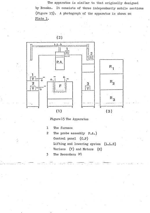
4 The apparatus and the nrobe 68
4.1 The apparatus. 68
4.1.1 The furnace . 69
Page
4.1.3 The control panel and the recorders. 75
4.2 The cylindrical prohe. 77
4.2.1 Precasting preparations. 79
4.2.2 Casting of the probes. 81
5 Experimental procedure 82
5.1 Experimental sequence. 82
5»1.1.1 Zero bath superheat. 83
5.1.1.2 Superheated baths. 85
5.1.2 Dissolution experiments. 85
5.1.3 Preparation of micro and macro structures. 86
5.1.3*1 Pb - Sn in their pure form. 86
5.1.3.2 Pb - Sn alloys. 88
6 F.esults 93
6.1 Chill-layer results. 93
6.1.1 Chill-layer growth at zero superheat. 93 6.1.2 Chill-layer growth and melt-back in super- 93
heated baths.
6.1.3 Microstructural examination of chill-layer. 104
6.2 Dissolution results. 105
6.2.1 Dissolution rates. 105
6.2.2 Calculation of mass transfer coefficient . 109 6.2.3 Visual observation of the probe surface . 118 6.2.4 Metallographic examination of the dissolving
probe materials. 128
7 Discussion 140
7.1 Introduction. 140
7.2 Theoretical treatment of the heat transfer
phenomenon. 140
7.2.1 A comparison of the integral profile methods 140 for cylindrical and planar cases at zero superheat. 7.2.2 Interface heat transfer coefficient. 143 7.2.3 The prediction of chill-layer growth and melt
back in the presence of superheat. 143
7.2.4 The conduction/convection model for heat flow
in the liquid metal. 145
7.3 Dissolution of lead, tin and lead/tin alloys
in molten lead/tin eutectic. 154
7.3.1 Mechanism of the dissolution process . 154 7.3.2 Effect of grain size,orientation and grain
Page
7.5.5 Morphology of the dissolution interface and
fluid flow. 155
7.5.4 Effect of rotation speed on dissolution rates. 158
7.5.5 Comparison with previous work. I5Q
7.4 Accuracy of comparison between the theory and
the experiments. 161
7.4.1 Heat losses dui-ing chill-layer experiments . 161
7.4.2 The accuracy of the theory. 163
7.4.2.1 Heat transfer phenomena . 163
7.4.2.‘2 Dissolution. 164
7.4.5 Errors cf measurement. * 164
7.4.5.1 Thickness. 164
7.4.5.2 Time. 164
7.4.5.5. Temperature. 165
7.4.5.4. Additional possible sources. 166
8 CorjpTusion.
APPENDICES
167
1 An attempt to grow a bonded layer . 168
2 . Tables of experimental chill-layer results . 171 5 Tables of experiment! dissolution results . 180
4 Analysis of materials used. 188
5 Physical and thermal properties of Pb, Sn,
Pb-Sn eutectic and stainless steel . I89
Homencleture. 190
Bibliography. 194
FIGURES
Page
Figure 1 Various morphologies of Alloy solidification . 21 2 The relationship between the ratio G/E. and solute
concentration, 22
3 The different macrostruetual zones in an ingot 23
4 The effect of cooling rate on the size and shape
of crystals , 23
5 Effect of different profile equations, for the radial temperature distribution, in an infinite
medium surrounding a cylindrical cavity, on the pre dicted surface temperature of the cavity. 28
6 Temperature distribution across a layer of solid
ifying metal under linear heat flow conditions . 29
7 Diagram of Taylor vortices . 37
8 Vortices between rotating cylinders . 39
9 Heat transfer during growth of the chill-layer,
on a plane finite wall. 46
10 Heat transfer during growth of a chill-layer on a
cylindrical probe . 47
11 Heat flow in the probe wall, 52
12 The relationship between the main program and the
subroutines. 6l
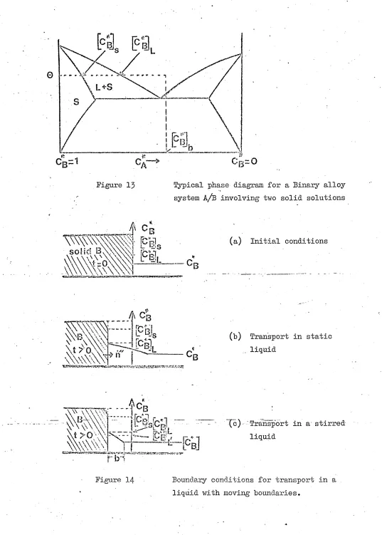
13 Typical phase diagram for a binary alloy system A/B
involving two solid solutions. 63
14 Boundary conditions for transport in a liquid with
15 The apparatus .
16 The Furnace •
17 Section of Rotating Probe support with sliprings. 18 Section of lead probe.
19 Parts of the steel mould . 20 Main reading area.
21 Chill-layer thickness versus time for zero superheat.
22 Wall-temperature’ versus time for zero superheat.
23 Chill-layer thickness versus time for 3°C superheat
24 Chill-layer thickness versus time for 7°C superheat 25 Wall-temperature versus time for 7°C superheat .
26 Chill-layer thickness versus time for 12°C superheat .
27 Chill-layer thickness versus time for 17°C superheat •
28 Wali temperature versus time for 17° and 20°C.
29 Chill-layer thickness versus time for 27 and
37°C superheat .
30 Wall temperature and probe - chill-layer inter
face temperature versus time for 27°C superheat .
y
31 Average rates of dissolution at 60 r.p.m. for pure lead.
32 Average rates of dissolution for pure lead at different rotation speeds but constant temperature
33 Average rates of dissolution for pure lead probes at 120 r.p.m, rotation speed #
34 Average rates of dissolution of pure tin probes
at 200°C •
35 Average rates of dissolution of 90$ Pb - 10$ Sn
probes at 230°C .
36 Lead - tine phase diagram .
37 Comparison of the present limiting mass transfer
coefficient with some other investigations.
38 Chill-layer thickness versus Time curves for planar
and cylindrical integral profile methods (zero
superheat).
39 Chill layer thickness versus exposure time.
Eutectic Sn-Pb, 20°C superheat, Pb insert ^ 40 Chill-layer thickness versus time (pure
conduction)•
41 Theoretical chill-layer thickness versus time curves for different half-life times
42 Chill-layer thickness versus time curves Stainless steel probe Pb-Sn eutectic bath.
43 Braking of Taylor vortices at high rotation speeds
44 Typical shapes of chill-layer during growth and
meltback .
45 The theoretical curves representing chill-layer growth, meltback, dissolution and cladding at 186°
PiATES
Page
Plate 1 The apparatus . 72
Plate 2 A close up to the rotax^n mechanism . 74.
Plate 3 The control panel of the apparatus * 76
Plate 4 Precasting arrangements. 80
Plate 5 Microstructure of Pb~Sn eutectic hath
as cooled in air, 89
Plate 6 Chill-layer growth on a Pb-probe under
unstirred conditions. 90
Plate 7 Chill-layer growth on a Pb-probe under
stirred and unstirred conditions . 91
Plate 8 Microstructure of the chill-layer . 92 Plate 9 A Pb-Probe, as machined prior to dissolution
experiment. 119
Plate 10 A dissolution experiment carried out
with Pb-probe without surface
Plate 11 Dissolution at a static Pb - Probe .
Plate
Plate
Plate
Plate
Plate
Plate
Plate
12 A dissolution experiment carried out
with Sn probe at 41 r.p.m.
13 A dissolution experiment carried out with a Pb - probe at 60 r.p.m,
14 A dissolution experiment carried out with Pb-probe at 40 and 80 r.p.m.
15 A dissolution experiment carried out with a Sn-probe at 60 r.p.m.
16 A dissolution experiment carried out with
Pb-probe at 120 r.p.m.
17 A dissolution experiment carried out with
Sn-probe at 60 r.p.m.
18 Macrostructure of a Pb-probe after a
dissolution experiment. Sectioned normal to the surface, viewed by oblique
illumination.
Plate 19 Typical ambiguous structure produced as
a result of incomplete preparation
Page
Plate 20
Plate 21
Plate22
Plate 23
Plate
24-Plate 25
Plate 26
Plate 27
Maorostructure of a Pb-probe after a
dissolution experiment. 131
Ditto 132
Surface structure of a 80$ Sn, 20$ Pb alloy before
... »
and after dissolution . 133
Microstructure of metals in Plate 22 . 134
Surface appearance and micro "’.tructiive of a 90$ Sn, 10$ Pb alloy probe after 40 secs.
of dissolution time . 136
Microstructure of a 90 wt $ Sn, 10 wt.
$ Pb alloy probe after 60 seconds of
dissolution time. 137
Macrostructure of a Snprobe after a
dissolution experiment . 138
Surface appearance and microstructure
of a 90 wt*
i°
10 wt. $ Sn alloy 139 probe after 100 sec. of dissolutionTABLES
Page
1 Chill-layer thickness results for "zero"
superheat. 172
o
2 Chill-layer thickness results for "3 C superheat. 173
ditto "7°C" " 174
ditto "12°C" " 175
ditto "17°C" " 176
ditto »27°C" " 177
ditto "37°C" " 178
8 ditto "47, 57, and
67°C." superheat. 179
9 Dissolution results. 106
10 Dissolution rates of pure lead probes in
Pb-Sn eutectic bath (30 r.p.m.) . 181
11 Dissolution rates of static pure lead probes
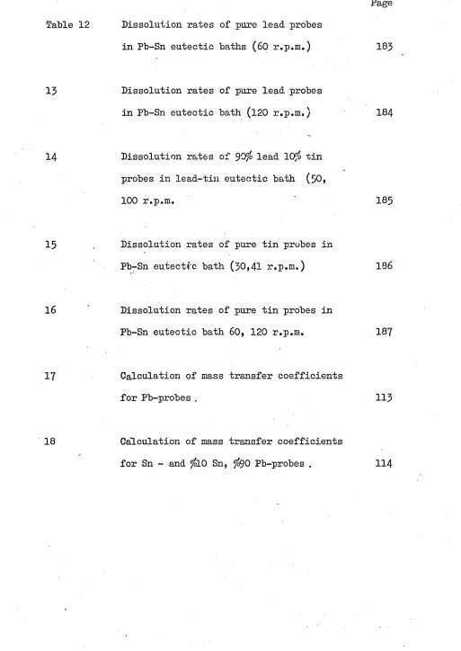
Table 12 Dissolution rates of pure lead probes in Pb-Sn eutectic baths (60 r.p.m.)
15 Dissolution rates of pure lead probes in Pb-Sn eutectic bath (120 r.p.m.)
14 Dissolution rates of 90$ lead 10$ tin
probes in lead-tin eutectic bath (50, 100 r.p.m.
15 . Dissolution rates of pure tin probes in Pb-Sn eutectic bath (30,41 r.p.m.)
16 Dissolution rates of pure tin probes in Pb-Sn eutectic bath 60, 120 r.p.m.
17 Calculation of mass transfer coefficients for Pb-probes .
18 Calculation of mass transfer coefficients
for Sn - and $10 Sn, $90 Pb-probes .
Page
183
184
185
186
187
113
1 INTRODUCTION
The idea of combining two materials by coating one with the other, to give a composite material, having the more desirable properties of
each of the components, has obvious attractions to metallurgists and engineers. In this manner the extra, cost of fabricating relatively ex
pensive alleys can be eliminated, and the savings can be used much more
satisfactorily in other directions.
Brooks has recently highlighted the difficulties of cladding by
casting processes.
Hills and Brooks have shown that the liquid metal must attack the surface of the solid metal if a bo .d is to be farmed in this type of
process, either by partial melting or by dissolution.
Strong bonds can only be produced, therefore, under certain specific
conditions of heat transfer.
■X-Hills and Brooks have designed an experimental apparatus in which
these conditions can be realized and studied, and have used this appar atus in attempts to bond stainless steel to cast iron and a lead/tin eutectic to lead. They have also used Hill*s integral-profile method ^
to predict the heat transfer conditions required to bond one pure metal to another pure metal. They found however some discrepancies between
theoretical and experimental results; this is thought to be partly as a re
sult of applying an integral profile method derived for planar shapes to an axi-symmetrical heat flow situation. They were not able to form a
bond between stainless steel and mild steel because of the high rate at which the stainless steel was dissolved by the molten mild steel, and because
of the apparently random nature of the dissolution process.
*
The main objects of the present work are to study the pre-cladding conditions, by investigating:
1 the heat transfer phenomenon occurring during solidification
and meltback of the chill-lpyer formed on a cylindrical rotating
substrate when immersed in melts at different temperatures, and
2 Literature Survey
After a brief review of the various processes for the cladd ing of one metal with another metal, an introductory review is presented
of the structure of cast metals. This is followed by a listing of the
mathematical methods for the prediction of solidification rates, followed by a detailed presentation of one integral-profile method.
The experimental apparatus used in the work described in this
thesis involves fluid flow and heat and mass transfer in an annular space between two rotating cylinders. Relevant knowledge about these
.1 Cladding
Increasingly dissimilar materials are "being brought together to solve material problems in all aspects of manufacturing.
Rolled gold and ’Sheffield plate' (silver on a copper based substrate,) were the earliest examples of cladding.
Hot pressure rolling or electro-welding, were the pro cesses used to join the coatings to the substrate.
Copper cladding of steel is especially useful for wire or tube, and is normally carried out by casting.
The ductilities and thermal properties of steel and nickel are so similar, that nickel cladding is particularly useful for steel.
Electro-welding,-hot compacting, (rolling or pressing), or casting, can be used to bond stainless steel to carbon steel, but the bond strength is generally dependent upon the quality of fluxing.
Shepherd and Brooks ^ have reviewed the major processes that have been used to produce stainless clad steels.
Although not yet widely accepted, lead clad steel sheet, produced by roll bonding has considerable potential.
The desirability of obtaining cheap aluminium coating for mild steel, has led to interest in applying metal powders to the
surface of steel strip, followed by a compaction or sintering process.
The Elphal process of Bisra has used electrophoresis to 2 3
deposit aluminium from a suspension in methanel.
A parallel Japanese development ^ uses atomized injection to apply aluminium powder to the steel surface, and to ensure bonding, after a drying operation, an adhesive of the polymetha-phosphate type is used.
5
Brooks has recently highlighted the difficulties of cladding by casting processes.
2.2 Solidification and its Structures
The structures of the solidified metals are determined by three major factors:
1 Alloy constitution; 2 Thermal conditions; 3 Impurities.
Metal composition governs the basic mode of crystalli- sation, end determines whether the equilibrium structure will consist of a single phase or eutectic grains, or both. The composition cf alloy is also characterised by the distribu tion a^d diffusion coefficients of the solute in the liquid, and solid phases, which- determine tendencies for
COnStitU-^r
'
tionai under cooling and segregation.
The temperature distribution and rate of cooling in solid ifying metals depend on the initial temperature conditions, and the thermal -rope: L'*es of metal and mould. Since wide variations in thermal conditions can occur at various stages during the cooling of a metal, its overall structure may con sist of separate zones with widely different characteristics.
The relative possibilities for nucleation and growth depend upon foreign particles, or solutes present in the
liquid, e.g. a pure metal solidifies with a plane solid/liquid interface, and the resulting micro-structure will only show very thin grain boundaries. When a minute quantity of solute is present, the solid/liquid interface will show small grooves, and the resulting micro-structure will show thick cell bound aries, (cellular structure). When the amount of solute is no longer small, its rejection may lead to the formation dend rites which can either be oriented in the heat flow direction
-D
ec
re
as
in
g
te
m
p
er
atu
re
g
ra
d
ie
n
t
INTERFACE
CELLULARCELLULAR INTERFACE
V..V
ORIENTED
ORIENTED DEK-RITES
V* fJ ' : 'i'W.'S
•.•'v'O
W y m f m
0>
c
« tu o k_ o cRANDOMLY ORIENTED
^ —-—*1 * * < % ‘J tf *„•*»** *
*«■" ' # * '** * » # (, * * « 1 »*. /* * «’'/*. ’ * '•"
i*. ; / / - •
** c • *
FIBROUS DENDRITES
tpCTFFM
[sj SOLID
rr^i f tr>l ME)
VARIOUS MORPHOLOGIES OF ALLOY SOLIDIFICATION
(a) do ng heat Row direction
(b) m icro stru ctu re norm al to beat flay/ a i solidus
fro n t
so
!u
te
co
n
e
en
t
ra
t
so
n
Figure 2
The relationship between the ratio G/h. and the solute concentration
A
The ratio /„ (where G is temperature gradient, and R the rate of freezing), is a significant parameter, with respect, both to mode of growth, and to final structure in solid solution alloys. These successive stages are illus trated schematically in Figure 1 and the associated thermal conditions in Figure 2.
The Macro Structure of Solidified Metals
It is generally recognized that three macrostructural
Figure 5
The Different Macrostructural Zones in an Ingot
zones st in one solidified ingot: 1 a "chill” zone ox fine griins,
2 a "columnar zone" containing grains elongated in the direction of heat flow,
3 a control zone of "ecuiaxed" grains.
These zones are shown shema^cally in Figure 3 and may occur in various proportions, depending principally upon the rate of heat extraction, the amount and composition of the metal, and the potency of the nucleans present. The metalographic examination at the neat extraction direction of the lead and
(b)
(c)
7
The Effect of Cooling Rate on the Size and Shape 'of crystals in a pure metals and intermetalio compounds,
tin probes used in this work showed the existence of the ’’chill” and ’’columnar” zones. Their significance and possible causes at the solution interfaces is-discussed later in the thesis.
In Figure 4? 'the effect of the cooling rate on the size and shape of crystals in pure metals, solid solutions, alloys and eutectics can be seen.
The Theoretical Solution of the
Problem of
Heat Transfer during Solidification
The unsteady state heat conduction problem, which deals with one dimensional heat flow during solidification, or melting of material, is often referred to as the problem of
"Stefan”. This problem has been the subject of numerous theoretical investigations, which can be divided into two broad categories.
(a) Approximate mathematical solutions using realistic and almost realistic solidification conditions, and
o o exact solutions under conditions rarely achieved in practice.
■*f
-Approximate Solutions
■ Two types of approximate mathematical methods which can be .used ares
(a) Numerical \nteg3 ^ion cf the equations by finite difference methods, and
o o integral profile technique.
The first method has the disadvantage of being very lengthy and tedious to apply, and must be repeated each time a parameter
■ * 8
is changed. The us'e of this method is described by Landau 9
and Forster.
The Integral Profile Method for
Planar Solidification
The integral profile method (sometimes known as the heat balance integral) reduces the nonlinear boundary value problem to an ordinary initial value problem, which gives useful sol- . utions quite easily and in many cases leads to expressions which can be solved analytically.
■presented in Chapter 3» and- a full account of ?t is given below.
Integral methods were first introduced by Von Karman and Pohlhauser in order to solve non - similar boundary
11 12
layer problems in fluid mechanics. Goodman has applied the 'Heat Balance Integral' to problems involving phase changes, and to problems involving the heating of bodies under Ifnear
13
and non-linear boundary conditions. This method was further used in analysing the melting of finite slabs
^
and for.3 5 materials with temperature dependent thermal properties.
Some numerical results for the case of a linearly varying sur face temperature, and for constant heat flux are presented in
16
-Reference.
An integral profile approach to the solidification of 17
alloys was used by Tien and Geiger who assumed in their treatment that the cooled surface remained at a constant temp erature below the solidus throughout the solidification
process. Thi3 unrealistic bour. laxy condition has been replaced 18
in a subsequent solution given by the same author. Koump 19
and Tiens
y
have developed a method involving a time depend ent surface temperature,20
Schneider considers radiation cooling of finite slabs, while additional comments on, and applications of, the integral
21 22 method are presented, in references * .
In his most recent paper Hills ^ has concisely described a general integral profile solution, which allows solidification rates to be predicted under a wide range of different cooling conditions. The method is a generalisation of the integral
*] ^ 23 2 profile methods previously developed by Goodman and Hills.
" 9
of it is given in Section 2.3.1.5
Application of Integral Profile Method to Non-Planar Solidification
In all the above mentioned papers, in Chapter 2.3«1.1» 21 22
with exception of References
9
the integral method has been applied to problems of planar geometry.22
Veinik treats several heat conduction problems, in both planar and non-planar geometries, under the assumption that the spatial temperature distribution are polynomial functions.
25
However, Sparrow in a recent discussion, has indicated that some inaccuracy is present in the application of Goodmans Heat Balance integral approach, with polynomical profiles to problems involving non-planar geometry.
25
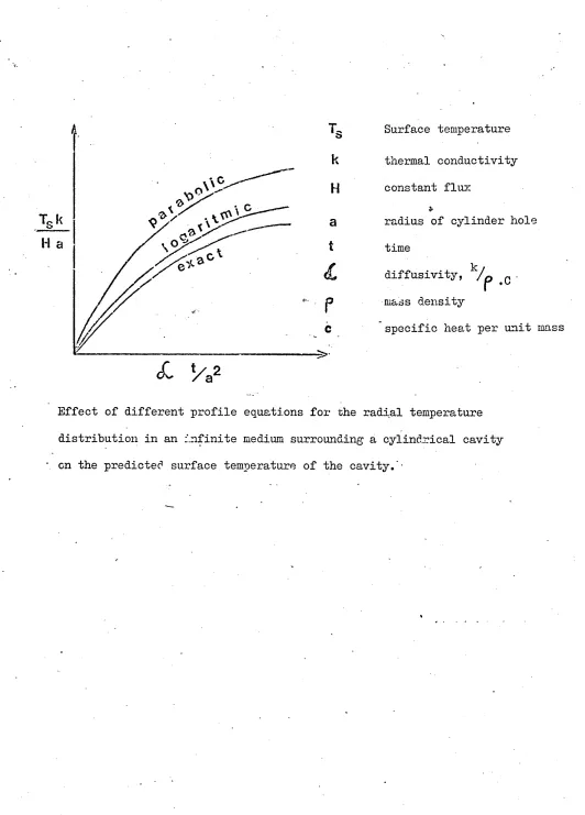
Thomas J. Lardner and Frederick V. Pohie analyzed the case in which a cylindrical boundary is exposed to a constant heat flux, and showed the surface temperature to be logarith mically dependent on the cylinder radius i.e.
T « U x (lnr) where U = T x r
Their result is presented in Figure 5 for parabolic and log arithmic profiles with the exact solution.
In the present investigations the cylindrical heat con duction equations has been used together with a linear profile, which has been found sufficiently accurate to tackle the
Figure 5
H a
L
*/a2
Surface temperature
thermal conductivity constant flux
radius of cylinder hole
time
k / diffusivity, /p #c • mass density
specific heat per unit mass
Effect of different profile equations for the radial temperature
[image:31.612.8.540.35.776.2]cavity.'-Hills1 Solution to the.integral Profile Method for a Growing Layer of Solid Metal/
[image:32.612.19.546.36.594.2]Hills1 solution is presented in terms of two parameters, the temperature of the cooled surface and the thickness of the solid layer. Two simultaneous ordinary differential equations are derived for these parameters. The derivation is discussed here in some detail as it provides a general illustration of the integral profile method and it forms the basis of the theoretical methods developed later in this work.
Figure 6 ' Temperature distribution
across a layer of solid
ifying metal under linear
q heat flow conditions
XrO
X - tThe above Figure 6 illustrates the growing solid layer, cooled at the surface, x = 0. Heat crosses the moving boundary,
x = t from the liquid metal. The temperature distribution within the solid metal must satisfy the unsteady state heat conduction equation
The integration of this equation across the solid layer yields
<£ 9 S
xcf'T' dx
(
2)
x
*
or applying the Leibnitz integral formula to the right-hand side,
t cf 0
-k
cf x^
d
r
dt
/ p . c0dx - Pc — (©) (3)
d
y j
o
1
1 dr,
t
Applying the heat conservation principle at the boundariei
U 0
- k
6
x and.
H- k
60dt
qt ' P H 7 r
Thus equation (5) becomes
PHf!_ 4" +
d r * + 9° d r
P
c0dx- pcQ
(4)
(5)
dt /
-/(
6)
dryThe most convenient auxiliary function to use in evaluating the integral in equation (6) is a quadratic polynomial.
/x / x \
The coefficients can be evaluated using the boundary conditions and equations (4)> which gives
s o qot
lX
'so that the integral becomes
±
(7)
0 dx= - 0 + -© - -
(
8
)
As the integral of an approximate function is more accurate than the function itself, the approximate integral can be substituted in equation (6) without great error.
Differentiating the resulting equation and re-arranging gives
*
The variables can he most easily expressed in dimensionless form as
. - f c / o *
•k _ Dimensionless thickness (10)
0 ks
* 9o
0 = -q— 11 surface temp. (ll) S /'n72
/q /
'Y
^ |— M time (12)
0g pek
H* H
cQs
latent heat (13)it
* q
q = M surface heat flux (14)
KJ
■|«o
Io
t It q *KJ
heat flux from liquid metal (15) In terms of these variables, equation (9) becomesh* + !
(1
- e*) - it ,* J “ * - £
-3 3 0
J
44 3 dS*0 *
1 1 d9° * *
- — = qo - qt
(
16
)
6 d ^
(
1-0)-Re-arranging equation (16) in forms of these partial differ entials gives
7 *
* * / dt 1 „ * * N
*
% I
J d(6
t (4+fo * ) ~ =d£* * 1 * p i
= qo - S + f6 <19)
Finally equation (19) gives a differential equation con sisting of two variables:
1 Dimensionless thickness of solidified metal 2 ” surface temperature of the metal.
But in order to solve the above equation, we require another equation and this can be derived by considering the variation of d0 across the solid metal layer.
aT
At the stationary surface, x = 0, we can write
[ “ ]- ! V (20)
M 0 d T
At the moving surface, x = t, the temperature is constant so we can write
d
[~6Ql at Tdt 1
— e(t
,T)
= / — / — +/— - / = 0
(21)
d
T
L 6 x J t dT L £>T
J tRe-arranging this equation and substituting for the temp erature gradient from equation (5) gives
d07 dt
fp
H dt q*r1
- --- (22) a
T[
k dT
kJ
Integrating the heat conduction equation (1) across the solid layer gives
-s «-i * / [ i * . j r t i l i r V L i
t L U , J o p
0
L 6 x vp
°
Jx
Substituting (20) and (22) into equation (23) we get dt /pH dt q" 7 dO k /ffo
_ _
L
---£ / _ o = _ / (24)dT
"I
k dT* kJ a'T
pc 6x6
othe value of ~~~ would not change very much within the solid 0
‘
layer and, assuming this change to be linear, the value of
6
5e— 7 will not alter significantly within the solid. The
0 x
integral appearing on the right hand side of equation (24) is thus given by
f - 6 ^ l ^ o l f *
J I r d Ja x " t / i ? i 0 (25)
Differentiating the heat conduction equation equation (i), with respect to x gives
1 4? ■ p° £ 5 V jr y
(2o>
Substituting equation ( 4 ) mfc (26) ant)(25) and writing this equation for x = o
it O dq^
: d r (27)
thus equation (24) becomes
dt f pH dt q" / d9 t dq"
-
~
— - " — (26)d / ^ k d 7 k j d
f
k d fRe-arranging (28) in terms of dimensionless variables and substituting from equation (18) gives
H *
d9
i Y a t V
/i
„ ,\d€ J + qt, 7 j + t f«
' (29)
* 1
d£ 1 + t fG
Substituting this equation in (19) we get a quadratic equa
tion in *
dt -*r \,,
*
C
it*\ 2*
at
-H. _| + r
\a t ;
Vd£ - -A.= o •
(30)
where -0. = E t (4 + t fQ ) (3l)
r-i* r— *
.
* \ * * ”7/ * * \ / \I = /
6
H +4
(1
-0
) -2
t q7
(1
+ t f ) (32
)* -x- . * t . “ w
+ q^ t (4 + t fQ)
A
= 6(q* -)(1
+tig
) - 3 * *d
(33)at
_ r
± f
+ 4-A/l
(34)
d£
2 /I
* * A*' */ /
Since is less than qQ , -/land dt /dvj will both be positive and the positive root of equation (30) is relevant. Multiplying both sides of equation (34) with
( lfp 2 + 4-A il + P ) we get
^ =
2 -^-
(
35)
d£
r’ + |[P~+
Equation (35) has no irregularities in this form and can be integrated numerically with equation (30) providing algebraic
2.4 Heat and mass transfer to rotating cylinders
Heat and mass transfer between rotating cylinders has been fairly extensively investigated. These transport properties are affected
very significantly by the geometry of the flow patterns between the two cylinders. At low rotation speeds a, laminar flow pattern is set up known as Couette flow in which the fluid between the cylinders flows in
a tangential velocity, there being a uniform velocity gradient across
the annular space. When the inner cylinder is rotating and the outer
v
cylinder is at rest, centrifugal forces will tend to cause fluid to
flow radially. This can result in breakdown of the laminar Couette flow, and this can strongly affect heat and mass transfer to the rotating •
2.4. 1 Fluid Flow between
Concentric Rotating Cylinders
A considerable amount of work has been done on fluid flow between concentric rotating cylinders concerning rotation of both cylinders, or one stationary, one rotating, with
different speeds as well as different directions. A large proportion of this work considers either a narrow gap, or non metallic fluids. Most of the fundamental work has been
30
reviewed by Forfman in his section on rotating cylinders.
31
Taylor, " in a very early paper, showed that above a critical speed of rotation, the laminar Couette flow breaks down into a flow consisting of a set of cellular, toroidal vortices spaced regularly along the axis of the two cylinders. Figure 7 shows a cross section of these three dimensional ring-shaped vortexes.
32
Hagarty has photographed such vortex patterns, using- the optical property of glycerine and water solutions, and concluded that there are three modes of flow when the annulus is very long:
1 When the inner cylinder rotates slowly, all particles move in circular paths concentric with the axis of the cylinders. This is a form of gouette motion.
2 As the speed of rotation of the inner cylinder is in creased, a stable secondary motion develops. Pairs of ring vortexes appear. In this motion each particle of fluid rotates simultaneously about the axis of the rotating cylinder, and about the core of the ring vortex, of which it is a part.
3 At relatively high speeds of rotation, the vortex motion becomes unstable, and the motion becomes generally
irregular and turbulent.
33
F IG .7 ;
oc LJJ D Z >“ O cc LiJ z z 0 ZI-<
H O cc /I / / //
/1 /
/ ] //
//
/
/
/
//
cc
LU Ors?
O £E LU H Zi o >CC
<
Zo
H <H-U)
Diagram of Taylor Vortices
in width with increasing probe rotation
speed-31
Taylor predicted the onset of the instability for a small gap in terms of inner cylinder radius R^, the gap be tween the cylinders b, angular velocity , and viscosity ,
in the form ' / 0/
R, b l>2 .
Ta , ^ ---
i
(36;
which is named the Taylor Number*
In the case of a large gap it is convenient to form the Taylor Number, not in terms of the inner cylinder radius R, but in terms of the mean radius Rm = J- (EL^
+
Taylor Number takes the form 2 3 O
Rm b
? O k
rn =
(3
7)
In addition to the vortices discovered by Taylor which arise
.
34
when the laminar flow becomes unstable, Pai observed vortices that are formed in turbulent conditions as a result of a secondary flow, at speeds which are several hundred times the critical speed. (Figure 8)
35 Recently E. H* Sparrow, W. P. Hunro and V. K. Jons son investigated the instability of the flow for the wide gap situation between rotating cylinders*. They produced critical Taylor Numbers for laminar instability covering a wide range of rotational speeds with different geometries.
They used the dimensionless term R4 q 2
*
T = — --
* 20
6 1z1
/ \
(38)
V
INNER CYLINDER WALL
- 5
9
-CO
0
u
r-i
&•H
Heat Transfer between
Concentric Rotating Cylinders
The three types of flow we have seen in the previous section are the main controlling factors for heat transfer between rotating cylinders. The simplest problem involving a rotating cylinder is the rotating cylinder in an infinite and still environment, where heat is transferred away from the cylinder by free convection.
Many authors are agreed on the strong effect of free convection at low rotational speeds, in wL.vch laminar flow and heat transfer by conduction prevail. For example,
•z£
-zn
Anderson and Saunders and Dropkin and Carmi have come to the similar conclusions, namely that at rotational Reynolds Number below about one thousand, heat transfer is virtually
un-affeo-f-ed by rotation, but between 1,000 - 10,000 the rotational Reynolds Number is c" importance.
58
W. M. Kays and I. S. Bjorkland combined the effects of rotation, free convection and cross flow, and formulated the Nu -- 1— ~ ----4-‘ —
for rotatirg Reynolds Numbers in the range 2,000 - 45>000*
"Whevn "NT ff'.T’nRR "Plow P p v n n lflR Wnrnhpr^ nnrl TT ^Cr'n.shof
Number) and for Np^ = 0.7» Equation(38.l)above reduces to
data for the case of the inner cylinder only rotating by the equation
Number) are negligible compared to Np^(rotating Reynolds
(
38.
2)
39
At high speeds of rotation Edmund and then Dropkin and
37 7
Carmi showed Nu Re
In a later paper Bjorklund and Kays ^ correlated their
Nu cond 0.175
v /2
(58.3)where N,r = Nusselts Number: N.Nu
9
]Nu cond= Nusselts Number for2.4.3 •Mass Transfer from Rotating Cylinders
Many workers have investigated mass transfer from
cylinders rotating about their axis especially since the role played by mass transfer in a solid/liquid reaction can be ascertained by examining how its rate is affected by varying the speed of rotation of a cylinder of the solid reacting in the liquid. King 42 dissolved rotating cylinders in aqueous acid using baffles, and found a linear dependence of
dissolu-43 tion rate with rotational speed. Ward and Taylor have studied the kinetics of the dissolution of a solid copper
cylinder in liquid lead and bismuth alloy and showed an approx imately linear power dependence.
Jackson and Grace 44 immersed a rotating zinc cylinder in bismuth allowing it to dissolve completely at constant speed so that the Reynolds Number decreased to zero during each experiment. The dissolution dependence was found to be nearly linear.
45
Roald and Beck used rotating cylinders in a study of rates of dissolution of magnesium and its alloys in hydro chloric acid solutions and found that the rate of dissolution increased with the 0.71 power of the speed of rotation. Eisenberg, Tobias and Wilke dissolved solid organic acids in different glycerol solutions. Using the rotor diameter as the characteristic length in the Reynolds Number they found a power dependence of 0.7.
Sherwood and Ryan 4^ investigated heat mass and momentum transfer data from five different sources and showed that -all the data is close to a 0.7 power dependence on Reynolds Number.
A O
Olsson, Koump and Perzak investigated the rate of — dissolution of rotating iron and Pe - C alloy cylinders, in.
graphite-saturated molten iron at temperatures below the melting point of the solid. They concluded that the rate of dissolution is controlled by mutual counter diffusion of carbon and iron in the boundary layer.
49
that the rate of dissolution of carbon in Fe - C alloys is controlled by the rate of carbon diffusion from the interface.
Both their investigations showed 0.7 power dependence on surface velocity.
50
Pehlke, Goodell and Dunlop dissolved steel in molten pig iron and found that the rate of solution is a function * of bath composition, temperature and stirring.
51
Lommel and Chalmers looked at lead cylinders dissolving in lead tin alloys keeping C -Cn \ 0.05 L U /
8F*
atoms (C beingL concentration of the dissolving species of Liquidis Line at a chosen temperature; Co - concentration of the dissolving species in the bulk liquid.) They discovered that dissolution was independent of rotation speed and thus concluded that thesurface reaction was the controlling step.
52
3. Theoretical Treatment
Introduction
The theory may he conveniently divided into two sections. The first part is concerned mainly with the heat transfer
phenomena and the second part with the dissolution process.
In the first section of the theory the dimensionless model of the integral profile method is given and the equations for cylindrical solidification are derived. These are basi cally applications of Hills integral profile method ^ to a different geometry by means of convenient modifications. The computer solutions for flat and cylindrical geometries describe the solidification and subsequent melt-back of a liquid metal in imperfect contact with a flat or cylindrical wall respect ively.
the second section of the theoretical treatment the different modes of dissolution are discussed and the
Dimensionless Model for a Growing Layer on a Plane Finite Wall
This model (Figure 9) has been extensively described Is 10 and B:
survey (pagel9 ).
10
6
by Hills and Brooks and is discussed in literature
The resulting differential equations governing the change of chill-layer thickness, inside-layer temperature and wall temperature with time are expressed in dimensionless terms as
*
dt
*
d©
2 y\?
-P + fr ‘+4
_/*
jQ-* /
\
* •
+qs 1
77"I+ 15 f*
*
f
* -i + t f •©(39)
(40)
d©*w
where
fl =
*
* 1
fg and f^ f * *©
i *
(
r* ( * *
* ' I
*
R
* + 3
* * . ^ .
H t (4 + t f9 )
*
@L*
+ 4(1-9*) - 2t* q^7(l+t* f * )+ qg t (4 + t f*)
w * *x / * * N * 6(qo - qt) (1 + t fG ) - 3t
being
I
* / / * *\ = 3k / (R + 3k )
* , * * x
3k (© - © )
x o w 7..#■ * , * -x-N / R (R + 3k )
(41)
(42)
(
42
.
1
)
(43)
(44)
(45)
Results obtained using these equations will be compared with those for the cylindrical case in section
6 2
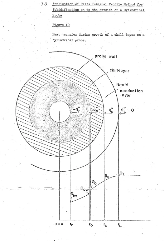
3*3 . Application-of Hills-'Integral Profile Method for Solidification on to the outside of a Cylindrical Probe
Figure 1 0 •
Heat transfer during growth of a chill-layer on a cylindrical probe.
probe wall
liquid
r conduction
\ layer
iw
As shown-in Figure 10 the cylindrical model can conveniently be divided into three zones: the probe wall, the chill-layer, and the liquid conduction layer. Heat trans fer in each of these zones is treated separately and a com plete solution obtained by a combination of the three .
3-3.1 Heat Flow in the Chill-Layer
A cylindrical interface between solid and liquid metal is considered during solidification (Figure 10) and the un steady state heat conduction equation is applied to the grow ing chill-layer. The Differential equation within the solid ifying metal in cylindrical co-ordinates, is:
or
. 6 8
= P°Tr
(46)Multiplying each side by r, integrating from r to r ando s applying the Leibnitz integral formula to the RHS gives:
(Leibnitz Theorem for differentiation: an integral with moving limits.
d
/
r
or _ '■dfe- ' da \f(x,y)dx =
j
— dx + f(b,y)— - f(a,y) — /a dy dx dx
6© rs r n rs r 6r _ r0
© +
r0 © *r
k
dr
dr 0 rdr - 9 r —
s s a
n
(47)The first term of equation (47) is evaluated by considering the conservation of heat firstly at the^ solidification front, which gives
0 p H dr
(48)
r = r
d r
- rSubstituting equations (48) and (49) into equation (47) and re-arranging gives
r t
dr
's
dT B
■
• rs< p H+ pcGs)
w ~
p° Tr / 0rdr =
~(
i
o
%-
xb
O
(50)
An approximation to the integral of the heat content of the chill-layer is made by assuming the temperature pro file to be linear
© 0 (r - r) - 0 (r - r)sx o / ox s '
(r - r )v o s' (51)
This profile satisfies the conditions r = r
0
=0
r = r0
=0
o o
Substituting (51) into (50) and re-arranging gives
pHr + —
-P s 6 (r +2r ) (0 -0 )' O s' ' S o'!
— (r q - r q x o^o s^-s'
)
drdr p c 'd0o
— a (r +2r )(r -r )—
d
T 6 s 0 3 0 &r
(52) ae
s o
To get a solution f o r the term --- must be evaluated.
a
r
ar
At the moving boundary
hence
r = r : 0 = 0 = constant so that d0 = 0s s
60
T)J
~ - + dr = 0. ’ <8r
Thus 6 0 <5 0
&
r6T
cSr6T
(55).
(54)
Substituting (55) into (54) gives
So
1 f U.
1
—
.
-1 r k I p H rd " 4s/ dr __s
a
r
(56
)At the inner cooled surface we have
. d0
69
Tr
r __a ro Assumingwhere b = _4_
f
<s ©) d 2edr i*rj
S
yoT
r.
(57)
“ d©"
_
7f_
r + b(r - r )v s' r'_r ,(58)
(59)
but
and
6 2Q
bT
c5rand at r = r
i © q
dr k
' k
6T
6 A 7
0
d 20 dr
1 dq ,
= - = b
k d
T
substituting (6|) into (58) givesd © © 1 fdA / ^-o11 \
\
Ir_
r 4 rr k
1
1 r — r
\ 0 s,
(
60
)
(
61
)
(
62
)
substituting .from ;(-57.) and~(56')”gives
d0
d r
H dr
d r
q dr
Hs s
k d r
r - rs o
k
VI
d r (
65
)calling *
67'
f ^ I and <5)90
then
ti
d q »
o »
f-= fry + 9
d
r
1
d 9
___
0
dr
9
(64)
Substituting (64) into (63) and re-arranging will give
d9 __o
d r
dr 2 / dr
\
PH sar
dr
s - (r - r ) f Vv so' T
k - (r - r ) f. ■ s
o'
( (65)Substituting (65) into equation (52) gives
A
drs+ r
fdrsl a r i ia r
-A =
02
where _Q_ = p He (r + 2r )(r - r )f x s o7' s o7
r - A . - (rB - r0) f0 -7
€ 6
pHrs ++ P o(r o +
2
C )(es - e o) _ 7 - q ^ P o
(
66)
(67)
(r + S 2r )(r - r )O S o
(
68
)
-/V = p c(r + r v s
2r
)(r - r )^ o7,k s 0 v “ 6(r q — r q )o4o s4s 7£
k - (r8 -r0) fgj
(69)dr
Since — - is positive whilst - r a"*> - r a" »o^ox s 4 s
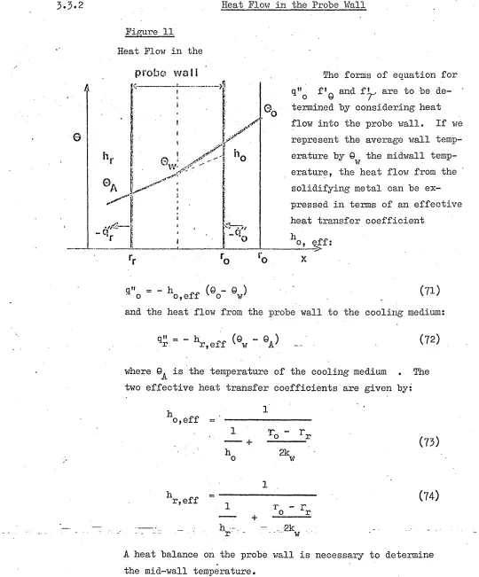
3.5.2 Heat Flow in the Probe Wall
[image:55.615.4.544.14.665.2]©
Figure 11 Heat Flow in the
probe wall
h,
0,w
a'-\ y
iy
y ^ A
h
o
©
A
-q:
.a .
-C?//'o 0 o
q" = - h (Q - © ) ' o o,eff v o w'
The forms of equation for q"o fVq and f ^ are to be de termined by considering heat flow into the probe wall. If
vie
represent the average wall temp erature by 0 the midwall temp-w erature, the heat flow from the solidifying metal can be ex pressed in terms of an effective heat transfer coefficientho, eff:
■ ua
-X
(71) and the heat flow from the probe wall to the cooling medium:
(72)
where is the temperature of the cooling medium . The two effective heat transfer coefficients are given by;
ho,eff =
h
T - r *o r
2kw (73)
r,eff
hr
(74) r - ro r
_ -2k
- •• w
A heat balance on the probe wall is necessary to determine the mid-wall temperature.
Heat loss by" unit length, of wall in unit time 2
Tlx
r r
Heat stored in unit length of wall
TT
(r2 - r ? . )v o r 7 P w °w __wdQd
r
Thusd©
Y
(r^ - r^ )p c —v r. 7 W w d / = - 2T
(r qn -r. q 0M0 r 4r7-)
(76)
(77)
o r
Substituting (7l) and (72) in (78) and rearranging gives (78)
d© r h (9 -Q ) - r. h „„(© -0.) w _ ^ 0 o,eff v 0 w r r,effv w A 7
d
r
0 r ' P w °wDifferentiating equation (71) with respect to time
(79)
dq o _ ,
i Y ~
" o,effd0 d0
o w
d
T
d T , (80)or,
d q 0 . . d9o
— m£r
ar
+ f eTy
(81)where, obviously
f • = - h
1 0 o,eff
+ h d0w
T ’ “o,eff
or substituting (71) into (83) we get
(82)
(83)
f =
Y
2K
o,eff r h ««(© -0 ) - r. h ^(0-9*) o o,effx ✓ 2 0 w7 2 sr
r.,effv tv. A 7•5« Heat Flow in the Liquid Metal
6
Brooks work revealed the invalidity of treating the heat flow from a stirred liquid metal to a solid in terms of a boundary
layer, of constant thickness having a constant heat transfer coef ficient. The shape of his experimental curves of solidified thick
ness versus time for different amounts of superheat suggests that the heat flux is very high at the beginning, possibly due to un
steady state heat conduction. The need for a more flexible model
led to the assumption' that there is a conduction layer close to the solidification front whose thickness depends on time but also on
the speed of rotation of the probe. This conduction layer lies ~ between rg and r^ as shown in Figure 10.
The thickness of this conduction layer was assumed to grow by unsteady state conduction during the early stages but then to
be ’ disturbed by the convection currents that develop as the bath of
eutectic metal becomes stirred by the rotating probe. Once this happens the conduction layer is assumed to decay in thickness, app
roaching the thickness of the imaginary stationary film that is equivalent to the convective heat transfer coefficient at the sur face of the probe.
The heat flux from the conduction layer can be represented’
by the heat conduction formula for heat conduction across unit length of a hollow cylinder:
• » 0 . d0 _ 2/fk (0T - 0 ) /Qcx
q = - 2r k
f
= - v L sx (85)dr _ In rT
rs rL
Expanding In — and taking the first terms of the series as an s