International Journal of Emerging Technology and Advanced Engineering
Website: www.ijetae.com (ISSN 2250-2459,ISO 9001:2008 Certified Journal, Volume 5, Issue 3, March 2015)
433
Feedback Linearization Control of Wind Turbine Based on
PMSG
A. Bennouk
1, A. Nejmi
2, M. Ramzi
31,2,3Power electronics and Electric drives laboratory, Faculty of Sciences and Technics, Beni Mellal, Sultan Moulay Slimane
University, Beni Mellal, Morocco Abstract—This paper presents a feedback linearization
control for a wind turbine based on a Permanent Magnet Synchronous Generator (PMSG). Considering the nonlinear relationship between the generator speed and generator currents, the generator side converter is designed by using a feedback linearization to control electromagnetic torque and generator speed. Standard vector techniques are used to control the Grid side converter. The validity of this control algorithm has been verified by simulation of a small scale wind turbine.
Keywords—Wind Turbine, PMSG, Generator Side Converter, Feedback linearization and Grid Side Converter.
I. INTRODUCTION
Wind energy is currently considered to be one of the most efficient and easily available resources that are able to provide a sustainable supply of energy to the world development. This status stems from its abundance, inexhaustibility, increasingly competitive cost, and environmental safety. However, its integration as a conventional production cycle is still difficult due to its dependence on climate conditions.
Wind Energy Conversion System (WECS) is made up of a wind turbine, a pitch angle control, a drive train, a generator and power converters. There are various kinds of generators used in WECS such as induction generator (IG), doubly fed induction generator (DFIG) and PMSG. PMSGs are emerging as the most-preferred technology of use. In contrast to their fixed-speed counterparts, the variable speed generators allows for operating wind turbines at the optimum tip-speed ratio and hence at the optimum power efficient for a wide wind speed range. However, the variable-speed directly-driven multi-pole permanent magnet synchronous generator (PMSG) wind architecture is chosen for this purpose of this research.
In fact, it offers a better performance due to its higher efficiency and less-needed maintenance operations because it does not have a rotor current. Moreover, PMSG can be used without a gearbox, which implies a reduction of the weight of the nacelle and reduction of costs. Optimum wind energy extraction is achieved through the Wind Turbine Generator (WTG) running invariable velocity speeds achieving, as such, higher energy preservation as well as a stress reduction [1].
Recent innovations in power electronics and control strategies have eased the regulation of the voltage and the frequency of the PMSG in many different ways. The present research analyses the model of a variable speed wind turbine equipped with PMSG connected to the electric grid via a rectifier and an inverter. It must be noted that this research focuses on a feedback linearization control of Generator Side rectifier which is used to control PMSG speed and torque, and then catches the maximum available wind power. Standard vector techniques are used to control the grid side converter in order to keep DC link voltage constant and then control the power delivered to the grid. The aim of this research is to illustrate feedback linearization as a control strategy to improve the system stability and reach the grid requirement under wind speed variations.
This paper is organized as follows: in the second section, a wind energy modeling containing two blocks is shown. In the third section, the feedback linearization is illustrated to control the generator side converter. In the fourth section a conventional approach is presented to show the control of the grid side converter. Finally, simulation with its results is presented.
II.WIND ENERGY MODELING
International Journal of Emerging Technology and Advanced Engineering
Website: www.ijetae.com (ISSN 2250-2459,ISO 9001:2008 Certified Journal, Volume 5, Issue 3, March 2015)
[image:2.595.41.544.147.393.2]434
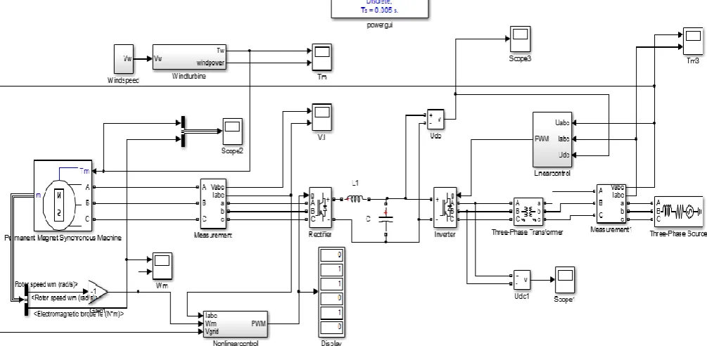
Fig. 1. WECS based on PMSG connected to the electric grid
A. Wind Speed Model
Wind speed model contains four components (equation 1) [1]:
( ) ( ) ( ) ( ) ( ) (1) Where Vb is the base wind component (constant), Vr is
the ramp wind component, Vn is the base noise wind
component and Vg is the gust wind, Vg is set to zero
during simulation, all of them in m/s. The model implementation of the wind speed in Matlab/Simulink is presented in Fig.2:
Fig. 2.Wind speed model
The kinetic energy in this level is given by:
(2)
Where m is the air mass, ρ is the air density, is the wind speed and S is the covered surface of the turbine.
B. Wind Turbine Modeling
Wind turbine is applied to convert the wind energy into mechanical torque. The mechanical torque of the turbine can be calculated from mechanical power at the turbine extracted from wind power. Then, the power coefficient of the turbine (Cp) is used. The power coefficient is function of pitch angle (β) and tip speed (λ). The power coefficient maximum of (Cp) is known as the limit of Betz.
The power coefficient is given by:
(
)
(3)
Where and
C1, C2, C3, C4, C5 and C6 are constants given by the
turbine constructor (C1 = 0.516, C2 = 116, C3 = 0.4, C4 =
5.1, C5 = 21 and C6 =0.0068), R is the rotor radius and ωm
is the rotor speed generator. The power coefficient is a nonlinear function of the tip speed ratio λ and the blade pitch angle β (in degrees).If the swept area of the blade and the air density are constant, the value of Cp is a function of λ and it is maximum at the particular λ optimum. Hence, to fully utilize the wind energy, λ should be maintained at λopt, which is determined from
the blade design, Cp is defined as:
[image:2.595.51.283.555.736.2]
International Journal of Emerging Technology and Advanced Engineering
Website: www.ijetae.com (ISSN 2250-2459,ISO 9001:2008 Certified Journal, Volume 5, Issue 3, March 2015)
435
And (4)
Where Pm is the mechanical output power of the
turbine, the mechanical torque is given by:
(5)
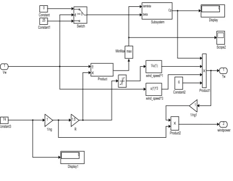
[image:3.595.46.286.247.433.2]The model implementation of the wind turbine in Simulink is presented in Fig.3:
Fig. 3.Wind turbine model
III. GENERATOR SIDE CONVERTER AND FEEDBACK
LINEARIZATION
The generator side converter is used to catch the maximum available wind power by controlling the torque and generator speed. This study focuses on a feedback linearization technique. Before applying this technique, remind below different mechanical and electrical equations in the generator side converter [4], [5], [6]:
(6) And ( ( )) (7)
Where Bm is the Damping coefficient, Jeq is the
equivalent inertia, Te is the electromagnetic torque, λf is
the magnetic flux linkage caused by rotating permanent magnets in the stator, Lsd and Lsq are the d-axis and
q-axis stator inductances that are, respectively ,composed of magnetizing and leakage inductances, id and iq are the
d and q-axis stator currents.
( ( ) ) (8)
( [( ) ] ) (9)
Where vsd and vsq are the d-axis and q-axis stator
voltages, Rs is the stator resistance, ω is the electrical
angular speed.
This non-linear system is presented by the following form: [ ̇ ̇ ] ̇ [ ( ) ( ) ] [ ] [ ( )](10)
In order to linearize the system, consider the MIMO system as follows:
̇ ( ) ( ) (11) ( ) Where ( ) [ ] [ ] (12)
And ( ) [ ] [
] (13)
[ ] and * + [ ] (14)
Since there are two control inputs, we have two outputs for input-output decoupling, then one input is used to control the line current and the other is used to control the generator speed. Therefore we choose y as:
(15) And (16)
The approach to obtain the input-output linearization of the MIMO systems is to differentiate the output yjof
the system until the inputs appear vd or vq,by
differentiating:
̇ ∑ ( ) (17)
Where Lf and Lg represent Lie derivative of h(x) with
respect to f(x) and g(x) respectively. If Lgihj(x)=0 for all
i, then the inputs do not appear and we have to differentiate again ,consider the system (10) :
̇ ( ) ( )
(18) ̇ ̇
(19) ̈ ( ( ) )
International Journal of Emerging Technology and Advanced Engineering
Website: www.ijetae.com (ISSN 2250-2459,ISO 9001:2008 Certified Journal, Volume 5, Issue 3, March 2015)
436
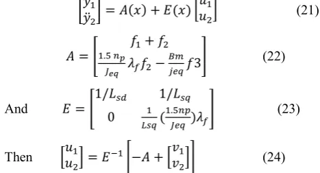
By differentiating, the new system is written as:
[ ̇
̈ ] ( ) ( ) * + (21)
[
] (22)
And [
(
)
] (23)
Then * + [ * +] (24)
For tracking control and to obtain a robust control facing parameter perturbation, then input system is given by:
* + [ ̇ ∫ ̈ ̇ ∫
]
(25)
IV. GRID SIDE CONVERTER AND FEEDBACK
LINEARIZATION
The grid-side converter is used to keep the stability of the DC-line voltage as well as controlling the active and reactive power. The grid side electrical equations are expressed in the d-q frame [7], [8]:
(26)
(27) Where is the -axis output voltage of the grid, is the angular frequency in electrical degree of grid, is the resistance, Ld and Lq are respectively the d-axis and
q-axis inductances, and are the currents of -axis and -axis, it is easy to figure out that the current of -axis and -axis can be controlled to moderate the active and reactive power, the voltage and current loops are illustrated. The inner current loop is controlled through PI controller. The output voltage loop produces PI controller for calculating the error between UDC and UDC
reference to produce reference. Therefore, -axis
current is set to be zero to decoupling control of the active power and reactive power 𝑄 by moderating the -axis current and the -axis current . The active and reactive power is given by:
( ) (28)
( ) (29)
If the reference frame is as vq=0 and | |, then
the equations for active and reactive power will be:
( ) | | (30)
( ) | | (31)
Such as Udc.ic is the power stored in the DC bus, then
active power is expressed by:
| | (32)
And the reactive power is set to zero.
V. SIMULATION AND RESULTS
Simulation model is given in Fig.1 .It consists of a wind turbine model, PMSG, three phases IGBT rectifier converting AC to DC, controlling the rotor speed and electromagnetic torque, and a three phases inverter controlling the Udc voltage and the transit power to the
grid [9], [10].
[image:4.595.45.279.157.283.2]Different parameters used during this study and different results are mentioned below:
Table. 1.
Wind turbine and PMSG parameters
Parameters Value
Base wind component (Vb ) 12m/s
Gust wind speed (Vg) 0
Gear ratio ( ) 1
Rotor inertia (Jeq) 0.3Kg/m²
Damping ratio (Bm) 0
Rs 2,75Ω
Lsd and Lsq 0,0085H
Number of pole pairs 4
Permanent magnet flux 0.175Wb
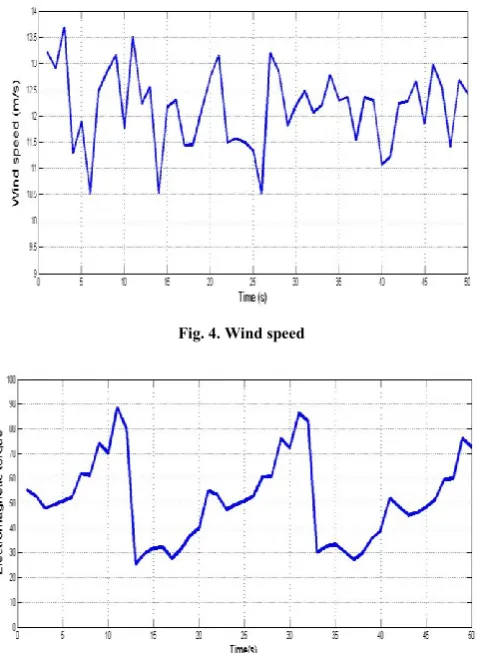
Fig. 5 shows the response of the system for wind speed variations. We notice that the generated torque tracks the reference and follows the optimum mechanical torque quite well. Consequently, the power follows the optimum curves up and extracts maximum power.
Fig. 6 shows the rotor speed generator, it’s observed that the proposed controllers can quickly and accurately tracks the desired reference.
Fig. 7 shows response of dc-link voltage. We can see that voltage is kept almost constant but less than 0.06 p.u which is within the safe range.
Fig. 8 and Fig. 9 show a good and a high stability performance of grid voltage and current at the power connection point.
[image:4.595.314.550.385.523.2]International Journal of Emerging Technology and Advanced Engineering
Website: www.ijetae.com (ISSN 2250-2459,ISO 9001:2008 Certified Journal, Volume 5, Issue 3, March 2015)
437
VI. CONCLUSION
[image:5.595.297.557.139.781.2]This paper proposes a feedback linearization to control the generator side converter of a small scale wind turbine based on PMSG, standard vector techniques are used to control the grid side converter. The different PID controller parameters are tuned to obtain the optimal performance. The simulation results show a good performance attained through the extraction of the maximum available wind power and through achieving grid requirement in the grid side converter. It should be noted that the generating system with the proposed control strategy is suitable for a small-scale variable speed wind-turbine based on PMSG. The simulation results demonstrate a very well dynamic and steady-state performance of the two controllers.
Fig. 4. Wind speed
Fig. 5. Electromagnetic torque
[image:5.595.316.564.143.469.2]Fig. 6. Rotor speed generator
Fig. 7. Udc voltage performance
Fig. 8. Grid voltage
[image:5.595.43.286.323.650.2]International Journal of Emerging Technology and Advanced Engineering
Website: www.ijetae.com (ISSN 2250-2459,ISO 9001:2008 Certified Journal, Volume 5, Issue 3, March 2015)
438
REFERENCES
[1] A.Rolan, A.Luna, G.Vazquez, G.Azevedo and D.Aguilar, ‘’ Modeling of a Variable Speed Wind Turbine with a Permanent Magnet Synchronous Generator’’, IEEE International Symposium on Industrial Electronics, July 5-8, 2009, pp. 734-739.
[2] S. Suganya, N. Manonmani, ―Simulation of Grid Connected Synchronous Generator with Controller ’’, International Journal of Emerging Technology and Advanced Engineering, Vol.4, Issue. 10, October 2014, pp. 119-123.
[3] S. Kumar Bisoyi, R.K. Jarial and R.A. Gupta, ’’Modeling and analysis of variable speed wind turbine equipped with PMSG’’, International Journal of Current Engineering and Technology, Special Issue 2, Feb 2014, special issue.2, pp. 421-426.
[4] D.Lee, ―Voltage control of PWM converters using feedback linearization’’, IEEE Transactions, 1998, pp. 1491-1496. [5] M.S.Merzoug, H. Benalla and L.Louze, ’’ Nonlinear control of
Permanent Magnet Synchronous Generators (PMSG) using feedback linearization’’, Revue des Energies Renouvelables Vol. 14 N°2, 2011, pp. 357 – 367.
[6] J.Wei, Z.Lin, N.Liu, ‘’LVRT Research of PMSG Wind Turbine Using Feedback Linearization’’, Energy and Power Engineering, 2013, 5, pp. 377-381.
[7] C.Wang, W. Lin and X. Le, ’’Modeling of a PMSG wind turbine with autonomous control’’, Hindawi Publishing Corporation, May 2014, article ID 856173, pp.28-30.
[8] K.Hong Kim, Y.Cheul J eung, D.Choon Lee, ’’LVRT Scheme of PMSG wind power systems based on Feedback linearization’’, IEEE Transactions on Power Electronics,Vol.27, No.5, May 2012, pp.2376- 2384.
[9] R.Teodorescu and F.Blaabjerg,’’Flexible control of small win turbines with grid failure detection operating in Stand-Alone and grid connected Mode, IEEE Transactions on Power Electronics,Vol.19, No.5, September 2004, pp.1323-1331. [10] Md. Enamul Haque, M. Negnevitsky, K.M. Muttaqi, ’’A novel